1/350 Scale Gulfstream IV-SP by R&R Modelers

Hi Everybody!

My name is Russ, one of the R’s of R&R Modelers, a friendship and collaboration between two modelers to make realistic small scale aircraft model displays. We are not a business, just modelholics who have fun making models. I’ve gotten into making models using AutoCad, and Ron (the other R) is a master of making mini-model displays in 1/350 and 1/144 scales.

Ron and I “met” through this very FineScale Modeler Forum, when he responded to my “A Career in Flight” post featuring a 1/350 scale display of the aircraft my dad flew during his career in the USAF (http://cs.finescale.com/fsm/modeling_subjects/f/2/t/157366.aspx). The planes in the display were designed by me in AutoCad and “printed” by Click2Detail (C2D), who shortly thereafter started a service in which designers can upload their CAD models and they print them, sell them and ship them, and the designer gets a percentage of the sale. I have made several models since then and they are available at:

https://click2detail.com/browse_products.php?total=146&incrementBy=9&id=&pagename_session=browse_products.php&id=&startIndex=27

Ron has acquired several of the models and started working his magic on them. You can see the magic he worked on the 1/144 scale Luscombe 8A Silvaire that I designed on his suggestion at:

http://cs.finescale.com/fsm/modeling_subjects/f/48/t/158982.aspx

And the work of art he is creating for the 1/350 and 1/144 scale Cessna U-3A (310B) at:

http://cs.finescale.com/fsm/modeling_subjects/f/48/t/159017.aspx

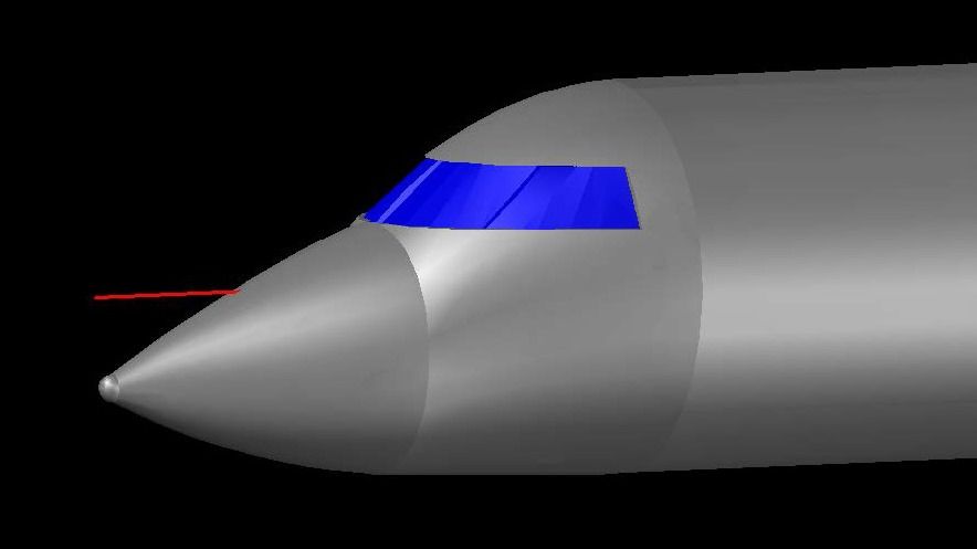
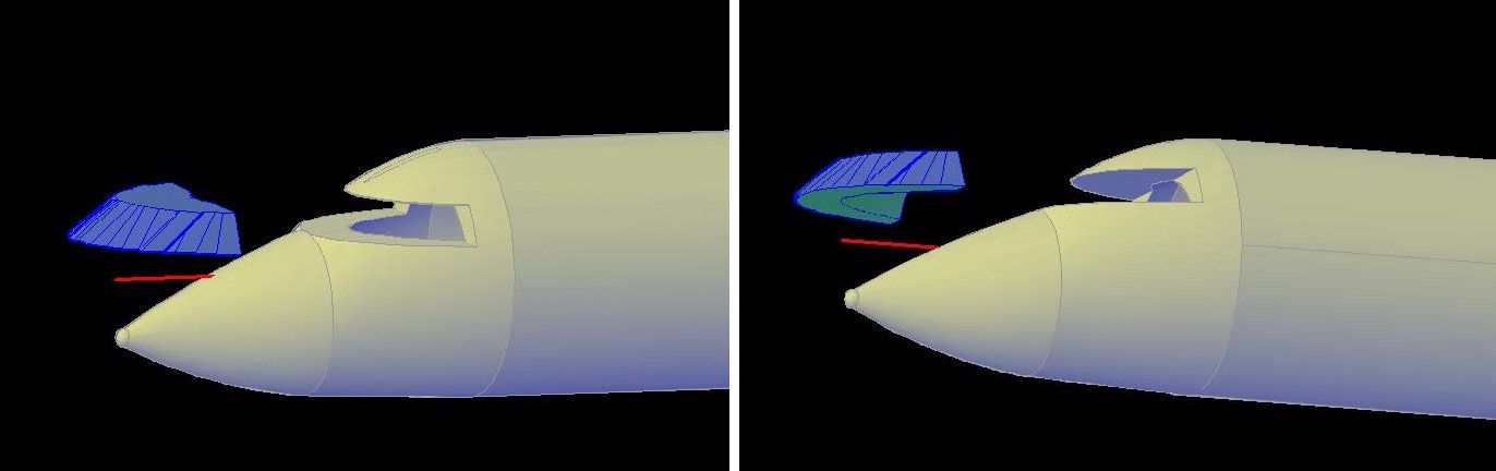
Here’s a peek at what Ron did with the Luscombe.

And here’s a peek at what he’s doing with the Cessnas.

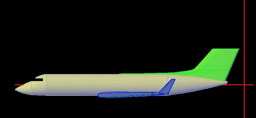
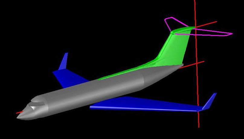
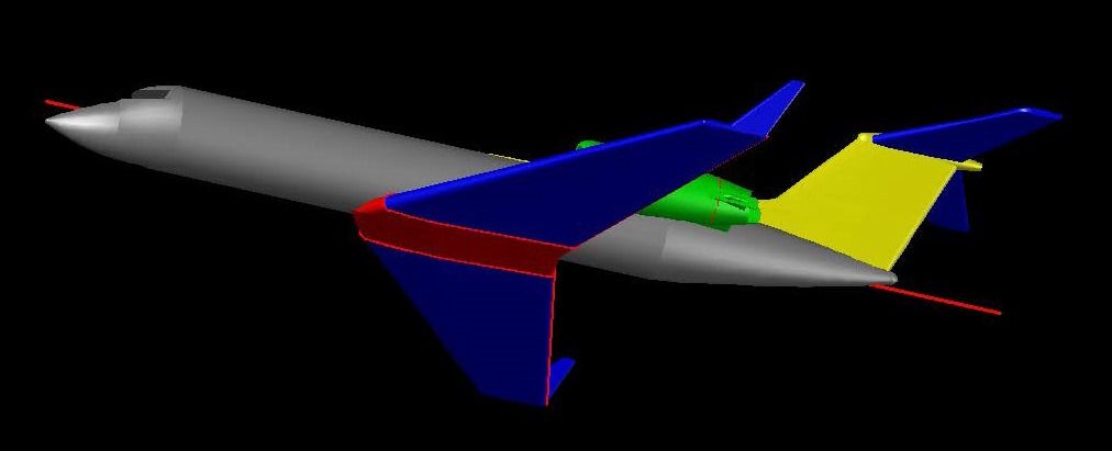
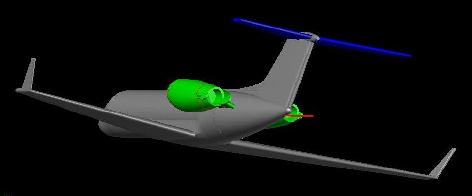
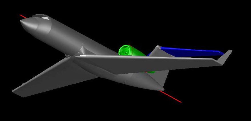
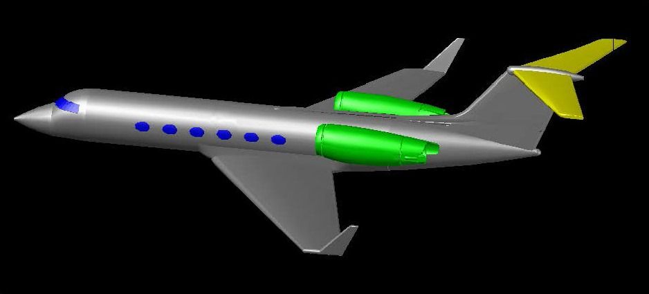
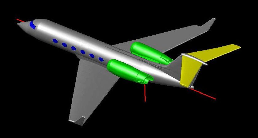
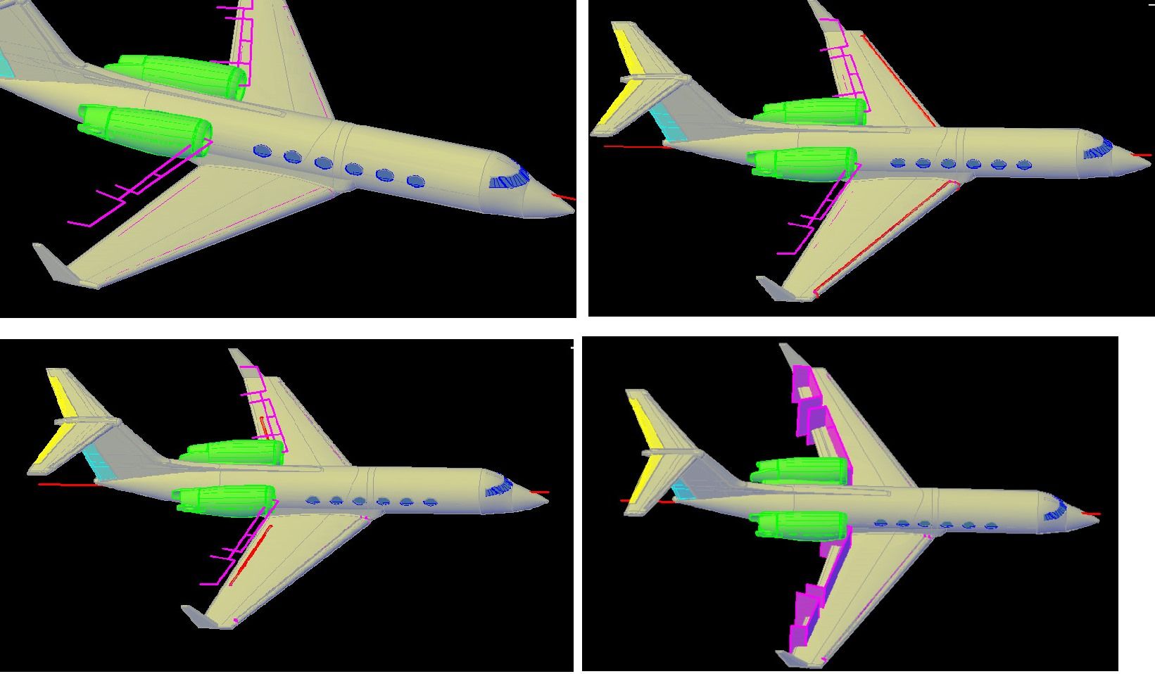
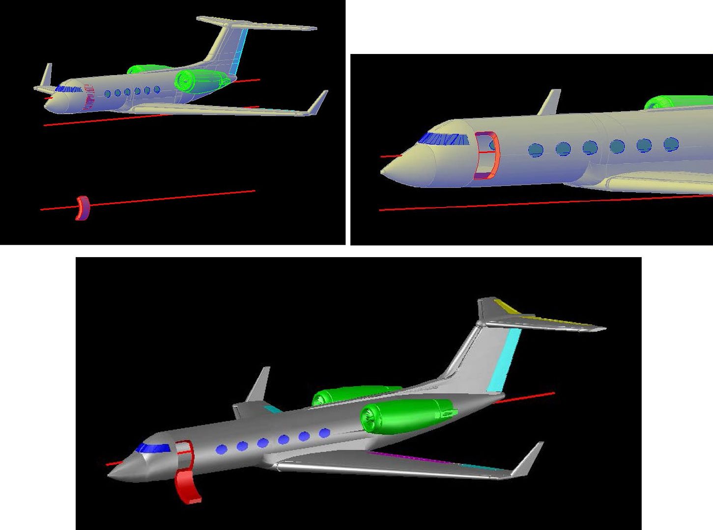
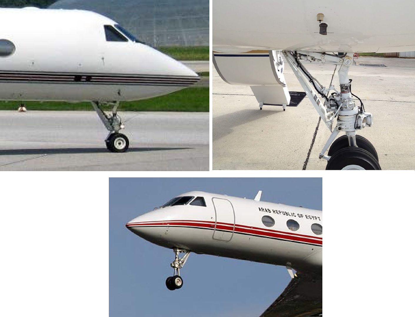
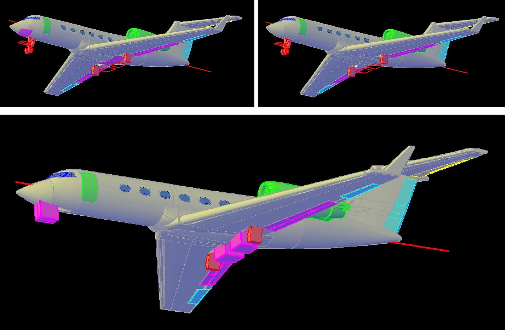
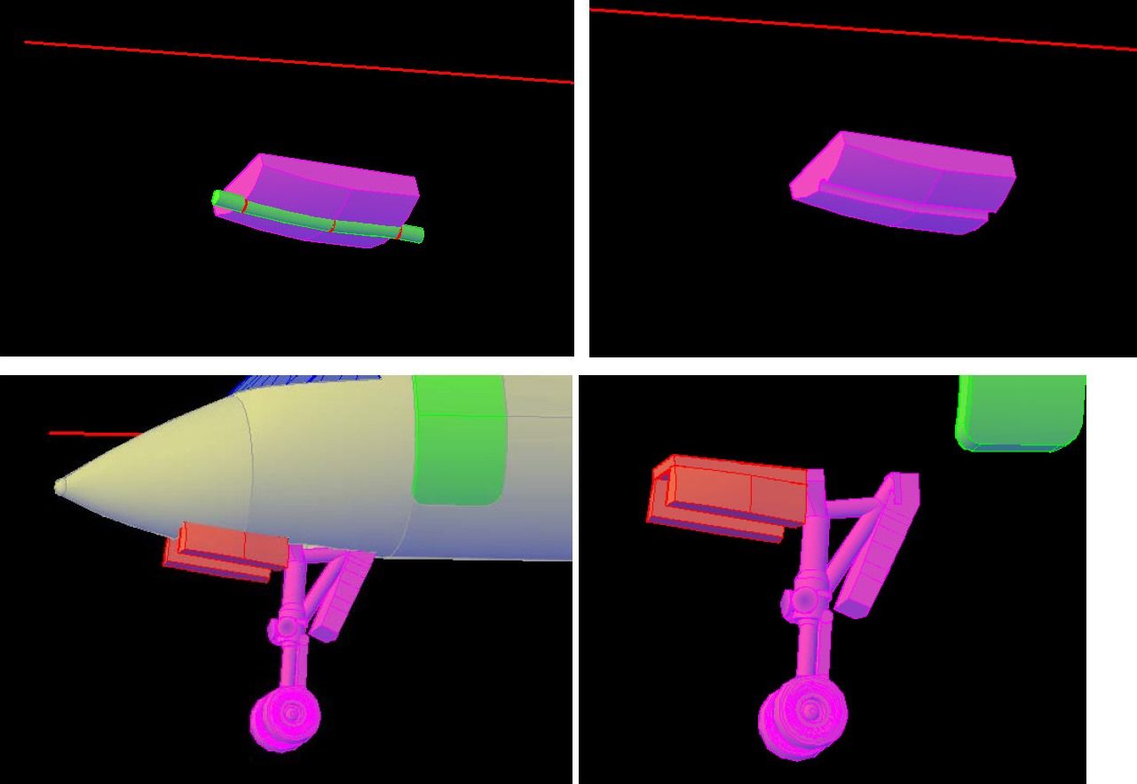
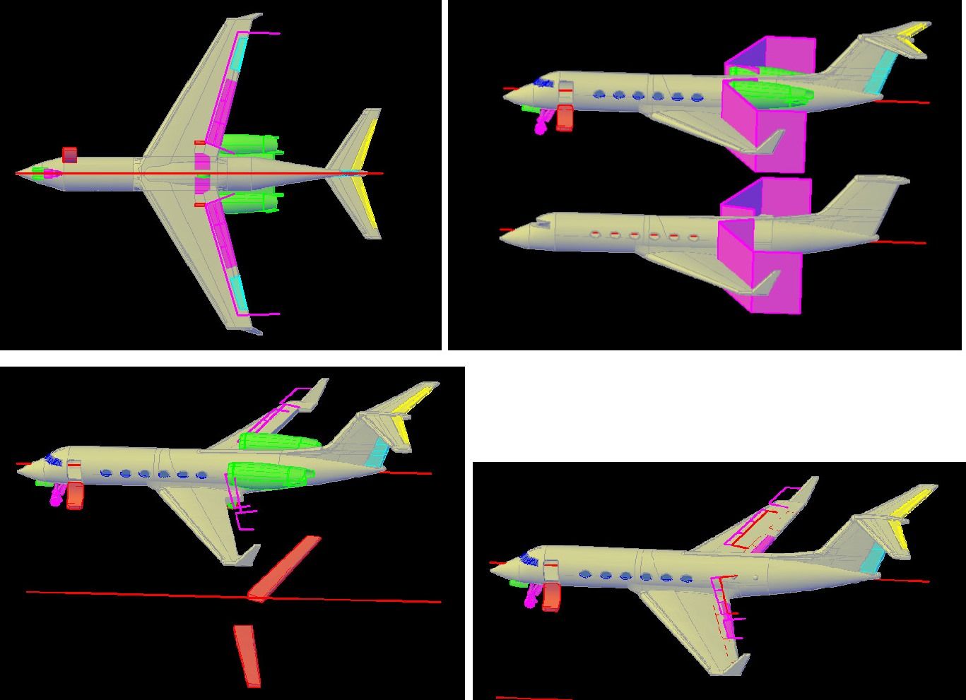
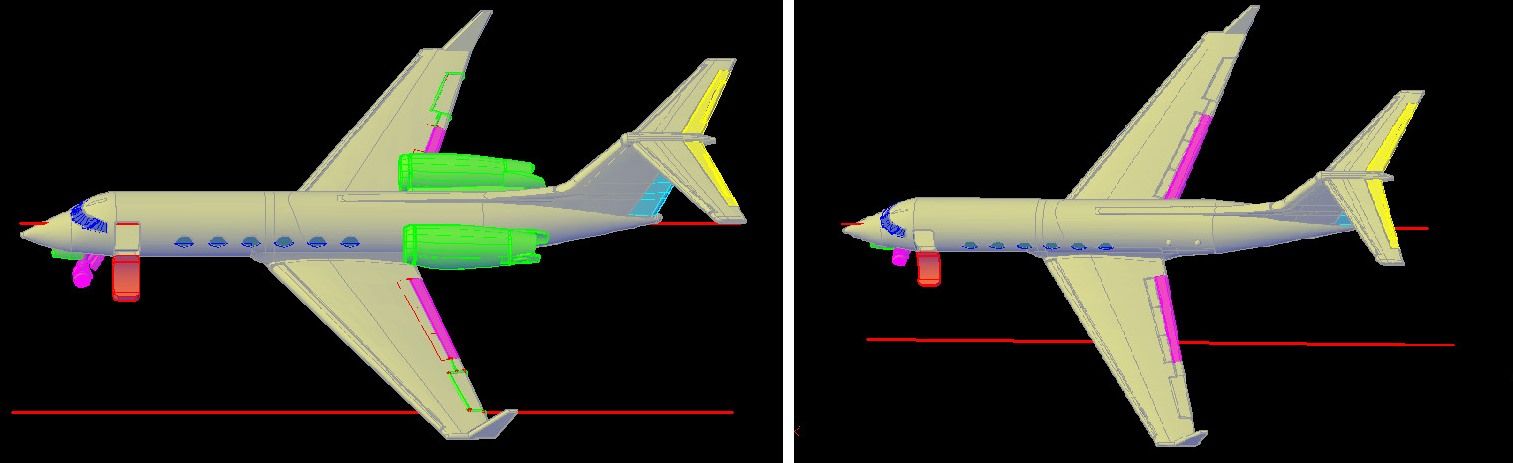
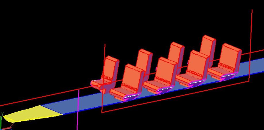
Ron is a pilot and flies a Gulfstream IV-SP, so I decided I needed to make one to add to my 1/350 scale fleet. It will be a good addition to the diorama I am planning to do with my models. In this thread I will show the step-by-step process I use to design the models.

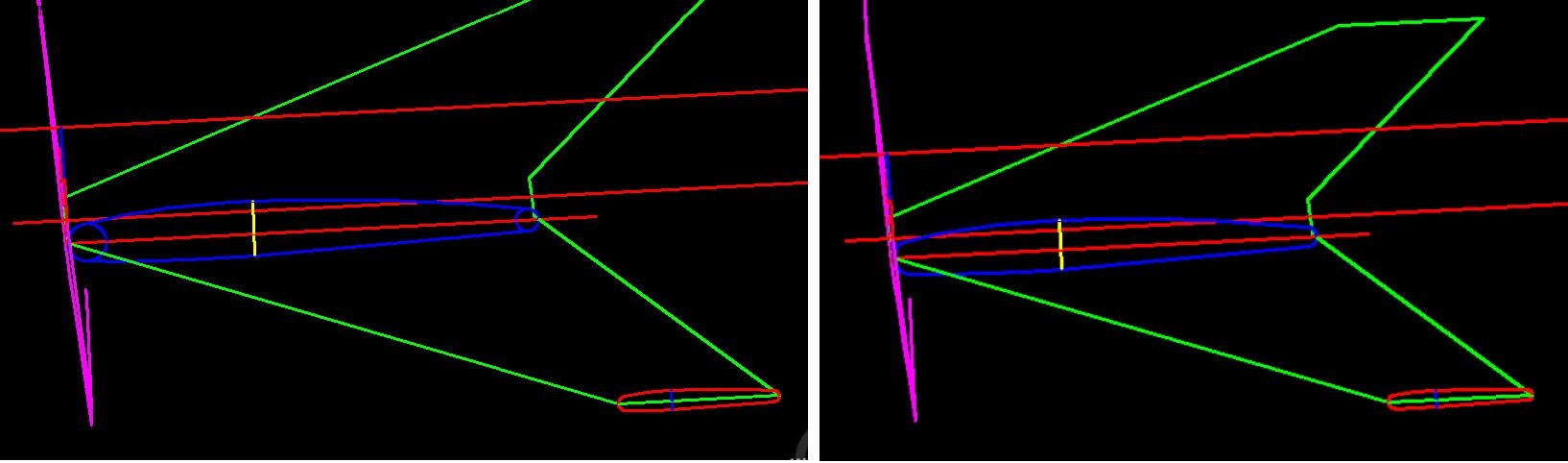
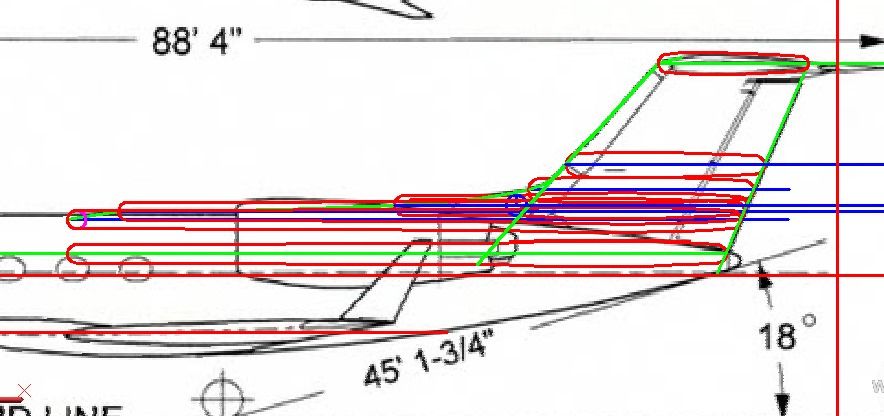
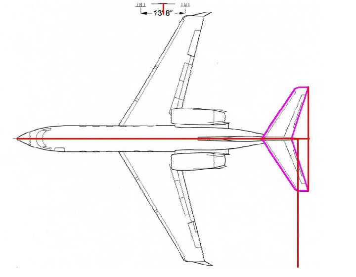
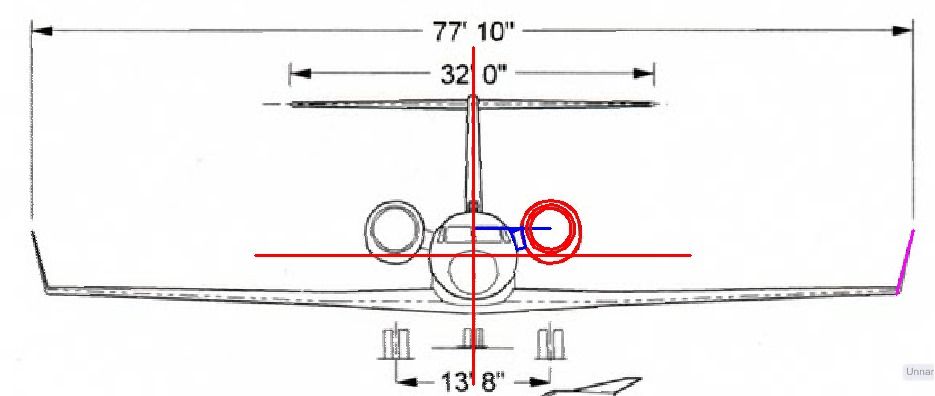
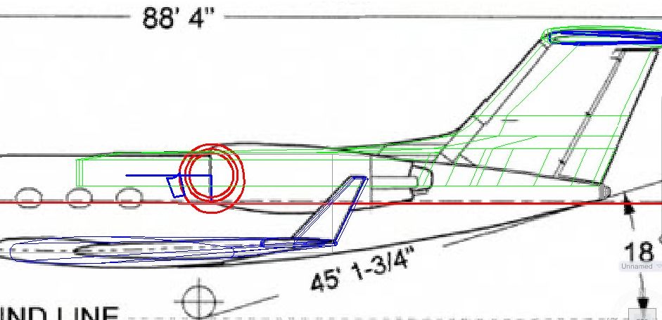
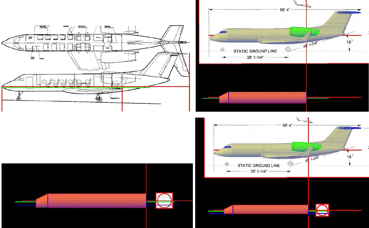
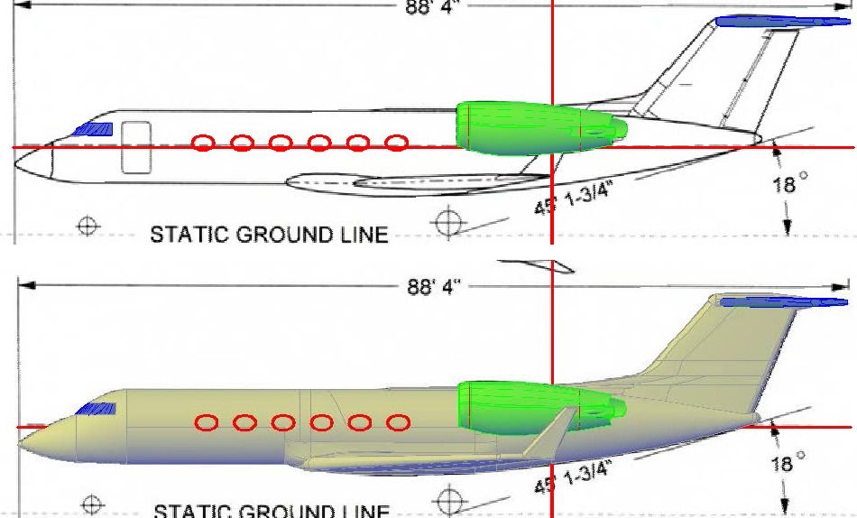
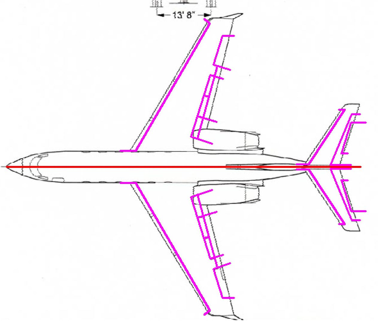
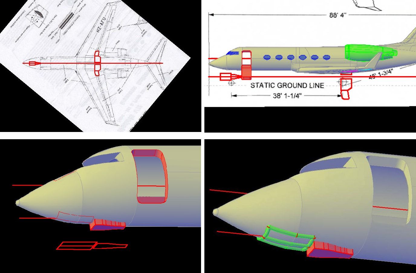
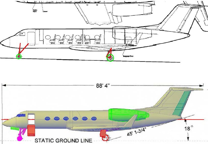
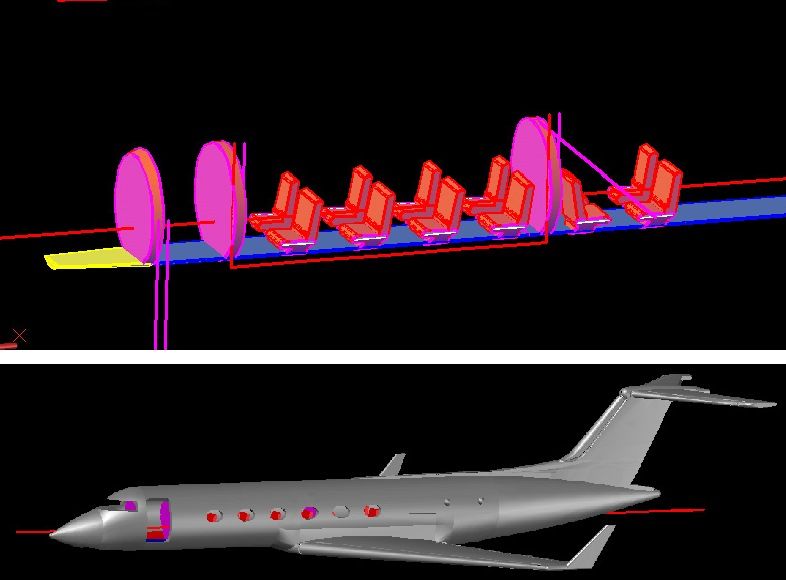
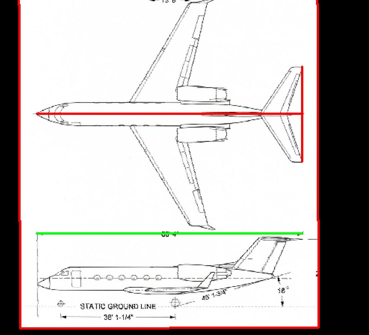
So, it all starts with getting plans, which thanks to the internet is fairly easy to do. I don’t need detailed plans, just 3-views, ideally with some cross-sections. Depending on the aircraft however, the sections may not be necessary, provided I can find good pictures of the subject, which is also made easier by the internet. For the GIV, Ron e-mailed me what I needed so I copied the drawings he sent into AutoCAD.

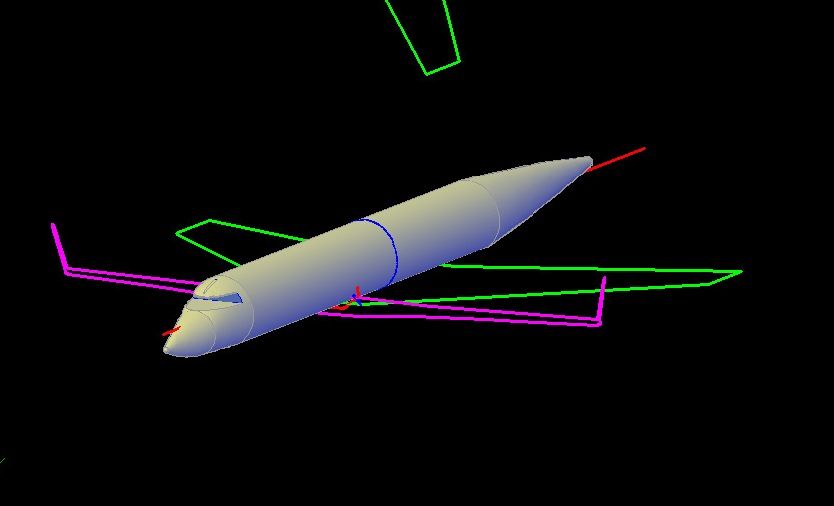
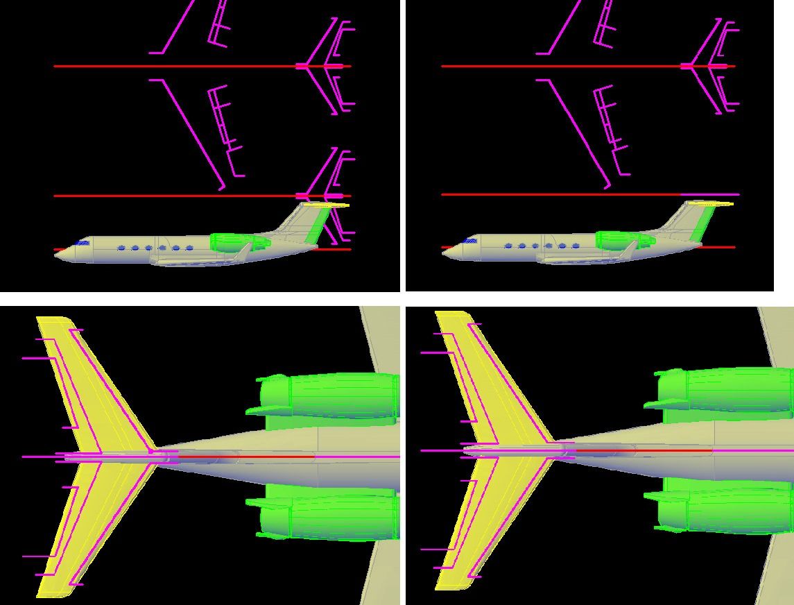
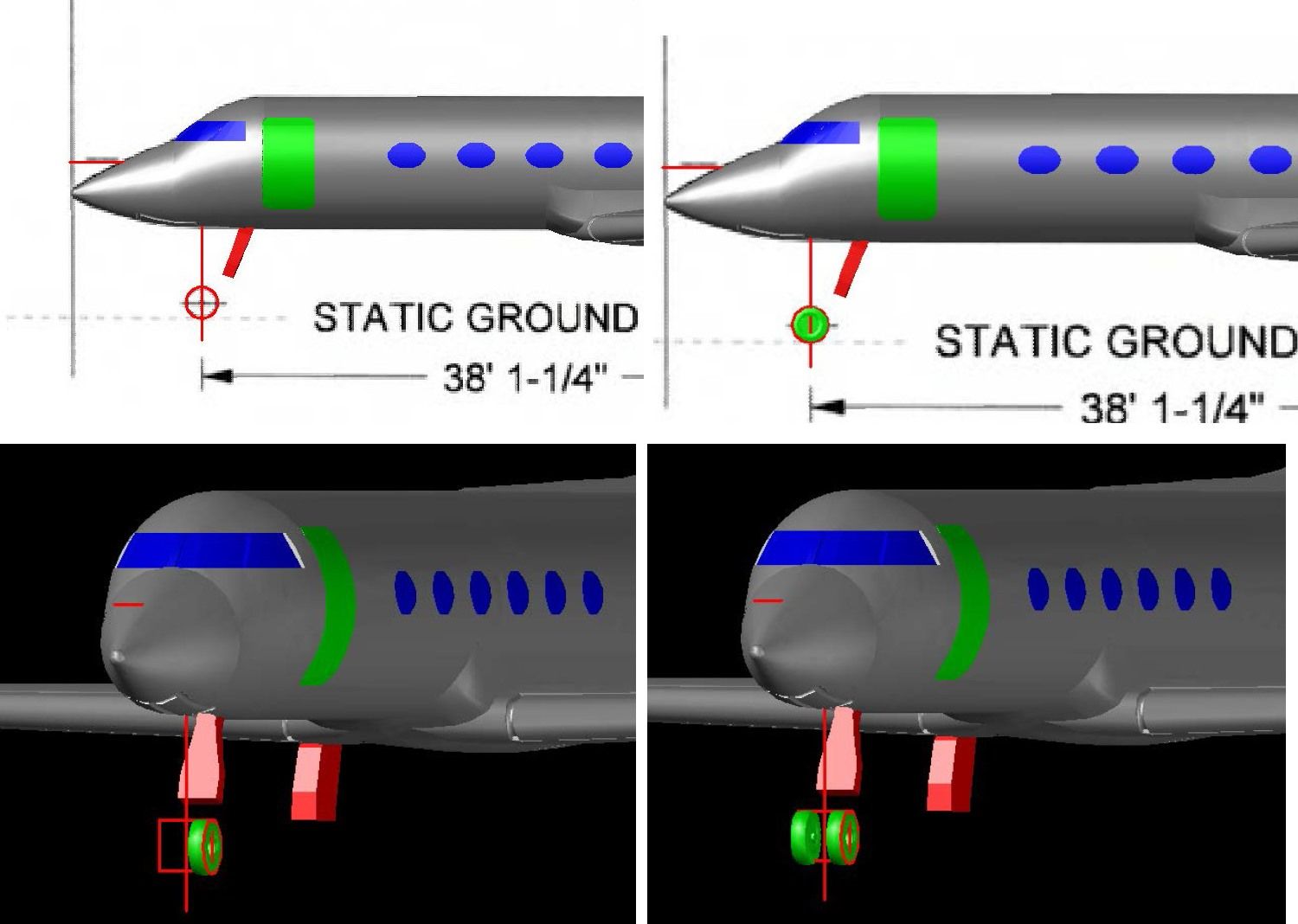
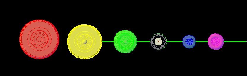
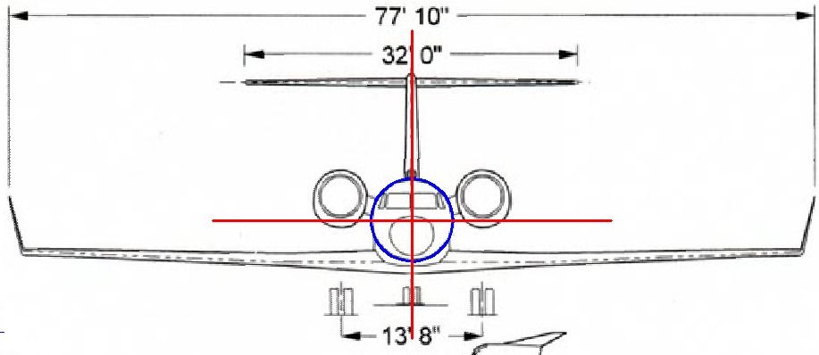
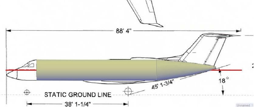
With the plans imported into AutoCAD, the next step was to scale then properly. This isn’t strictly necessary at this point, as I could make the model at any size and scale it later, but I prefer to scale it first so that I know what size things will be as I draw them, without having to convert them. The plans show the length of the plane to be 88’4”, with a wing span of 77’10”. At 1/350 scale, the model will be 3.03” long, with a wingspan of 2.67”. The green line is 3.03” long so I scaled the plans up to match.

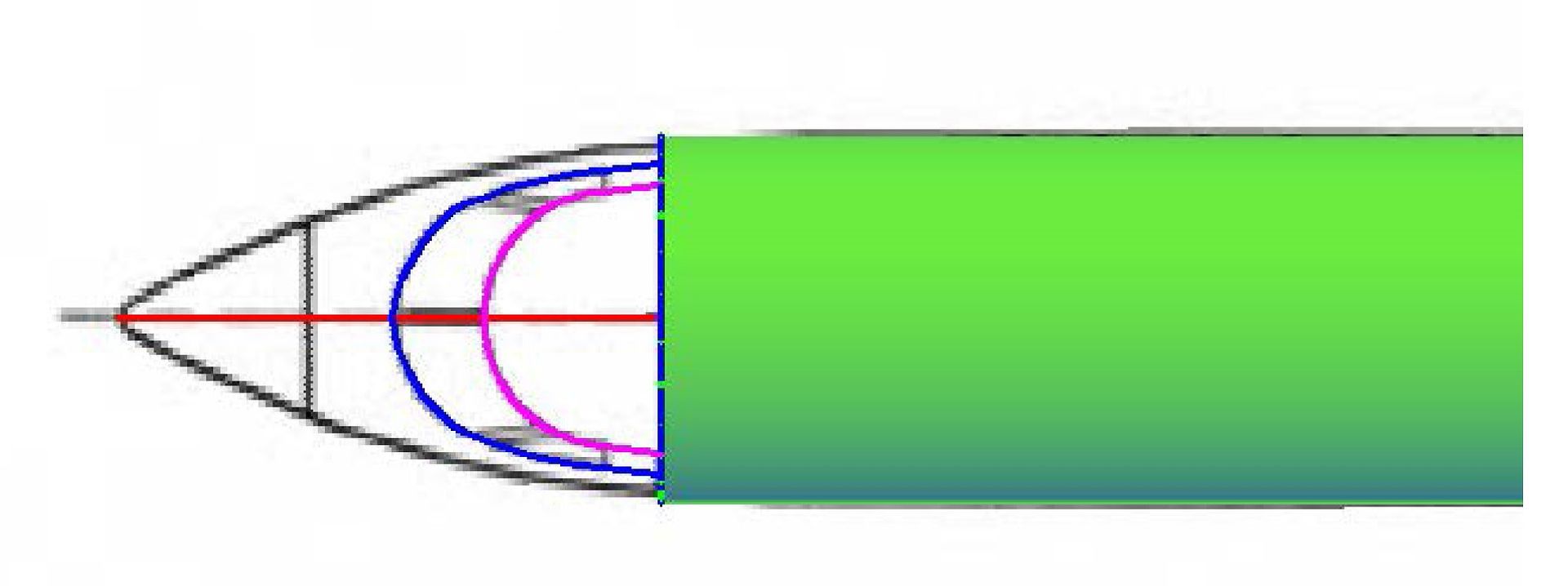
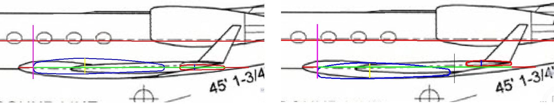
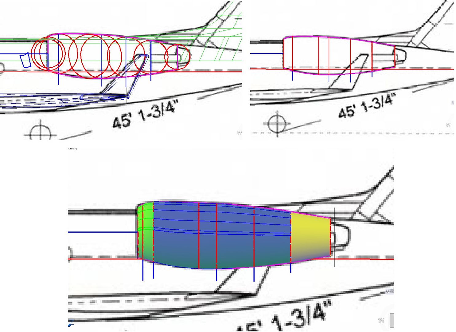
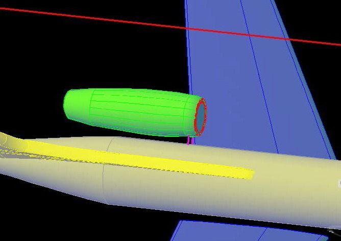
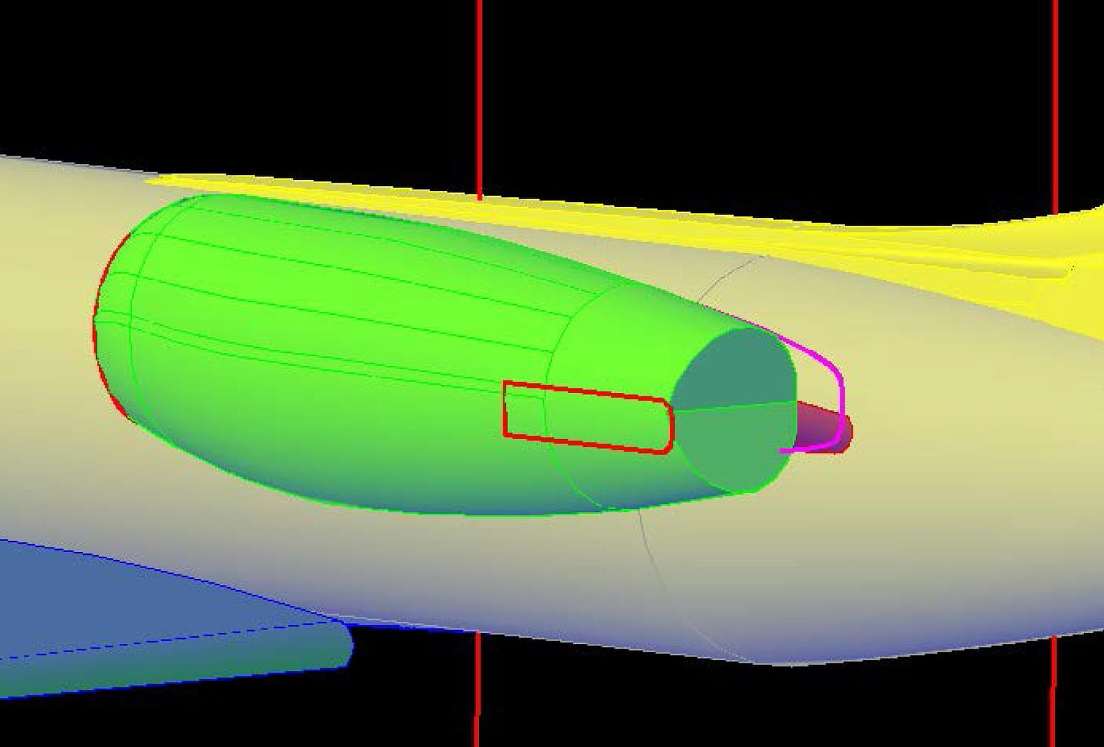
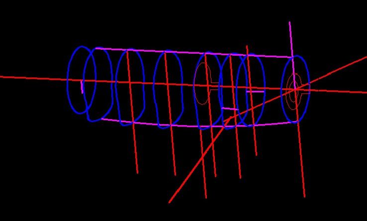
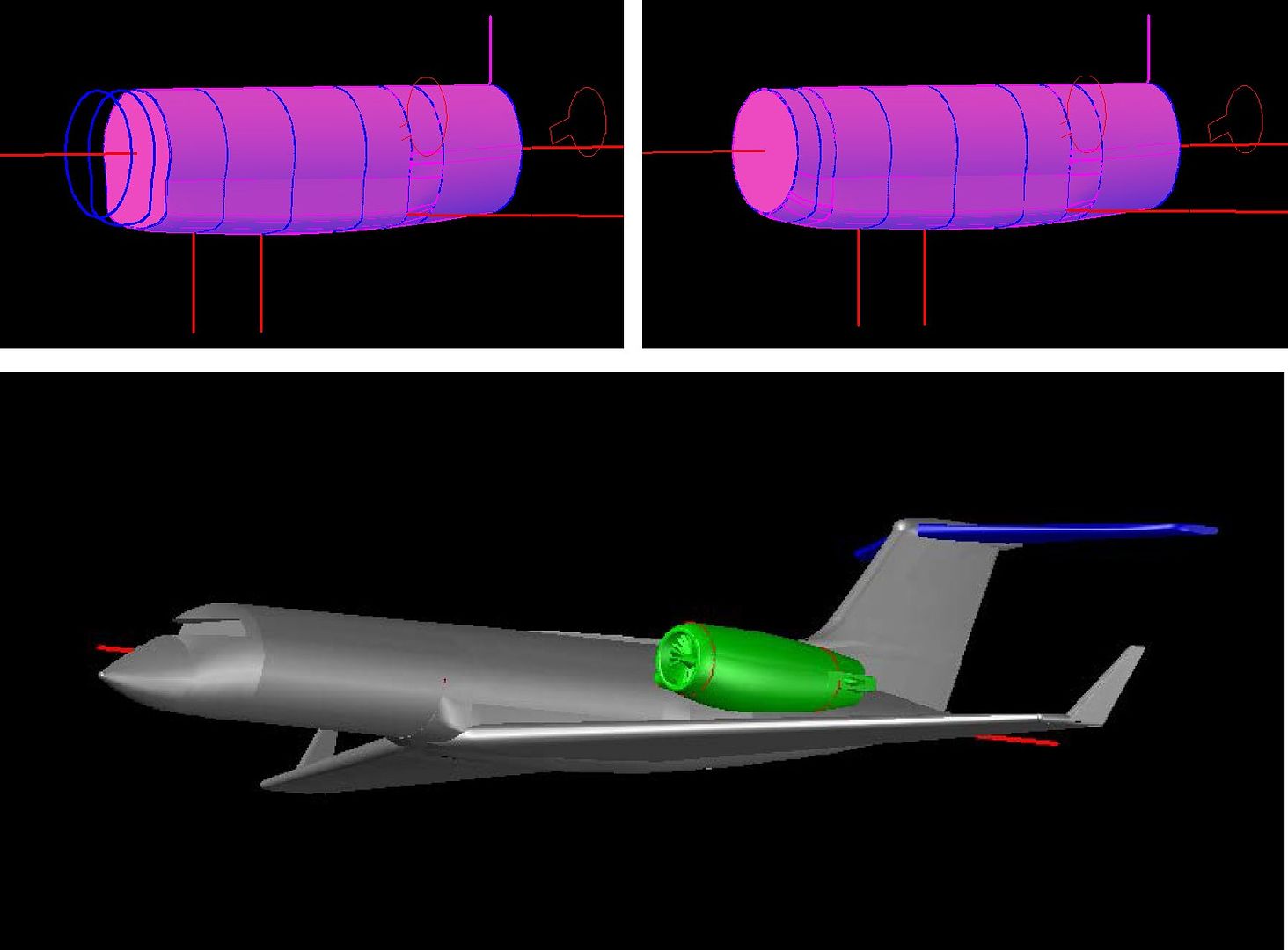
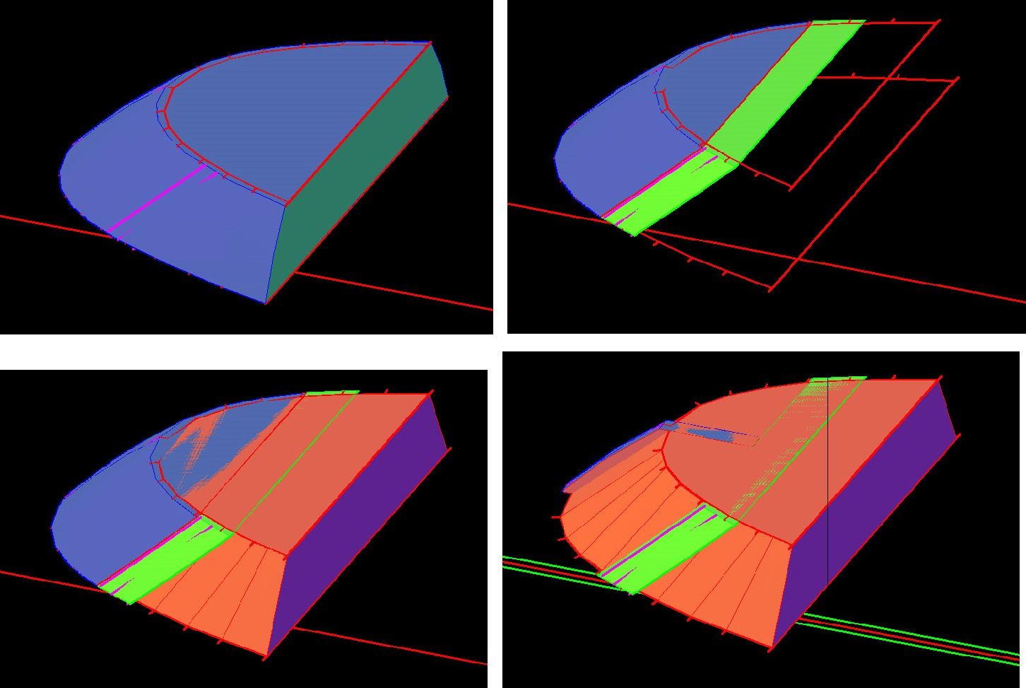
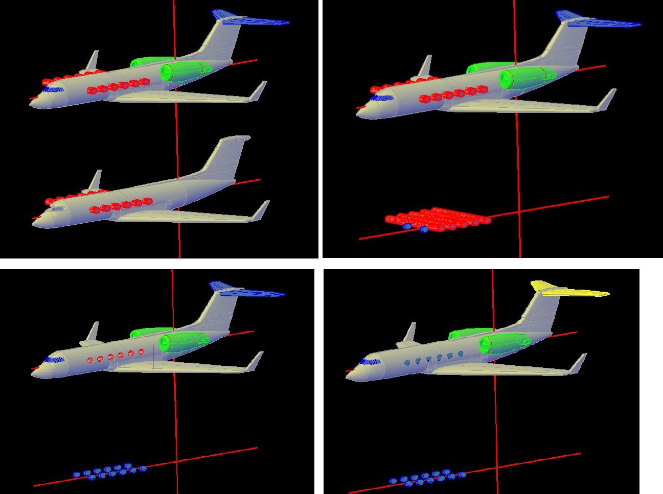
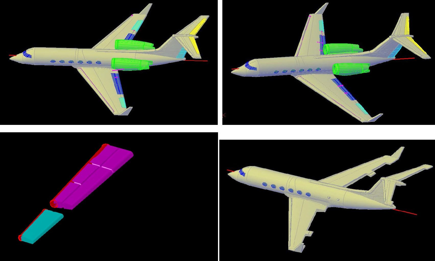
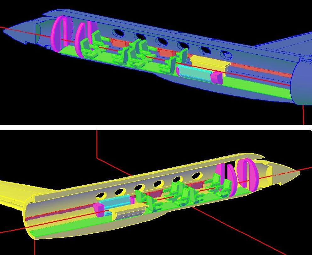
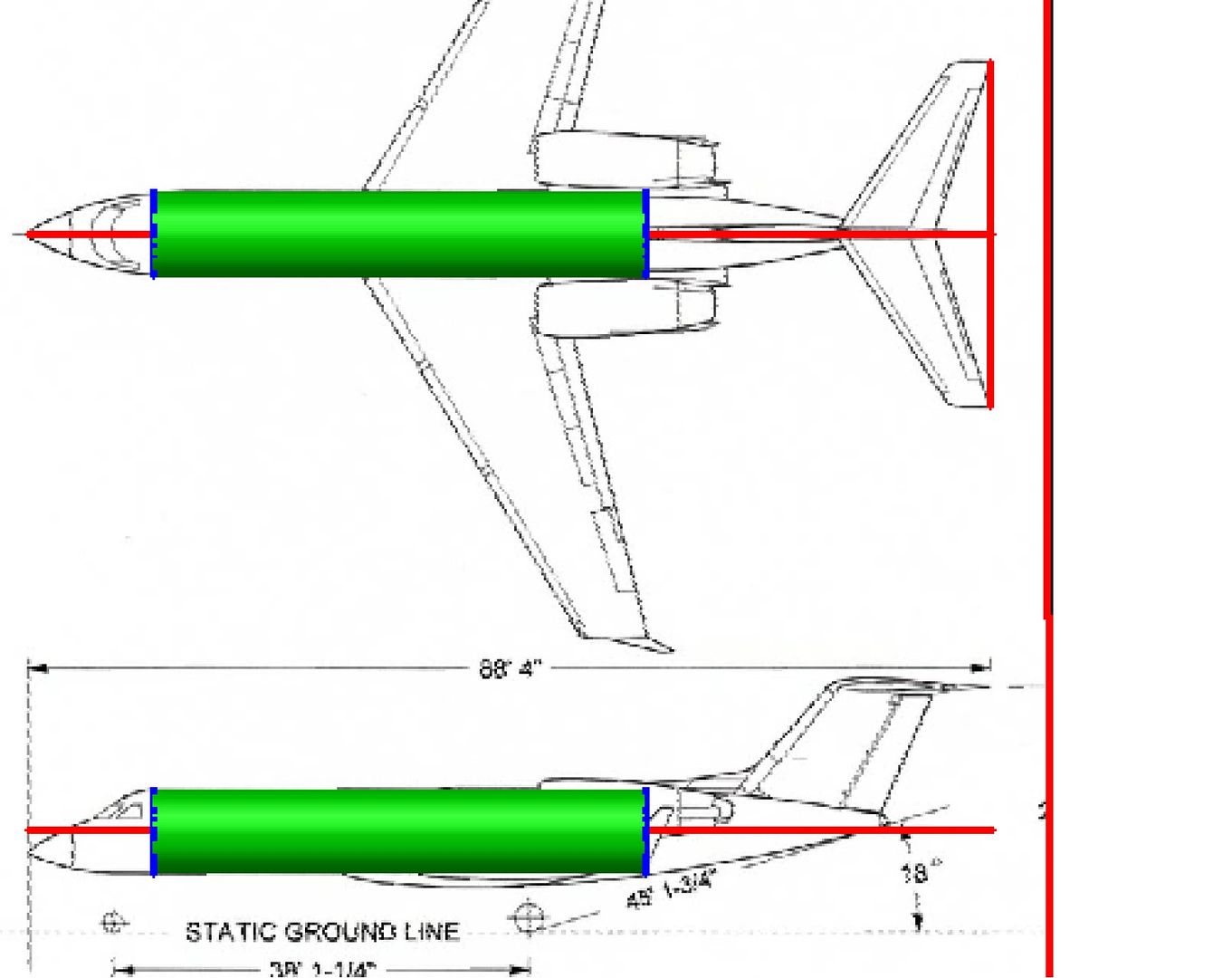
I typically start with the fuselage. In this case, I don’t have sections, so I started by drawing a circle matching the outline of the central part of the fuselage.

I copied this circle to the top and side views of the aircraft.

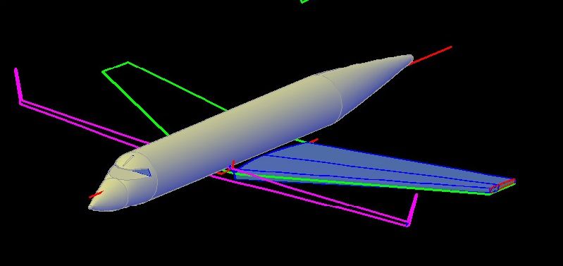
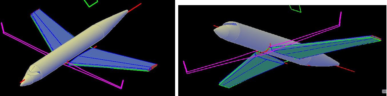
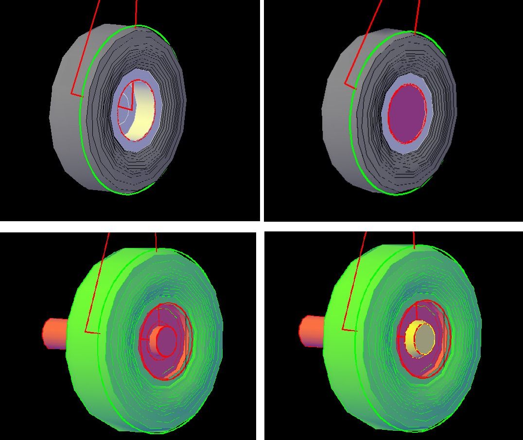
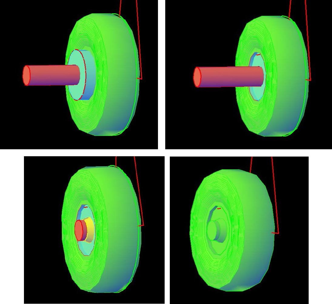
At this point, I rotate the circles so that they are perpendicular to the centerline of the fuselage and use the Loft Command to create a solid between the circles.

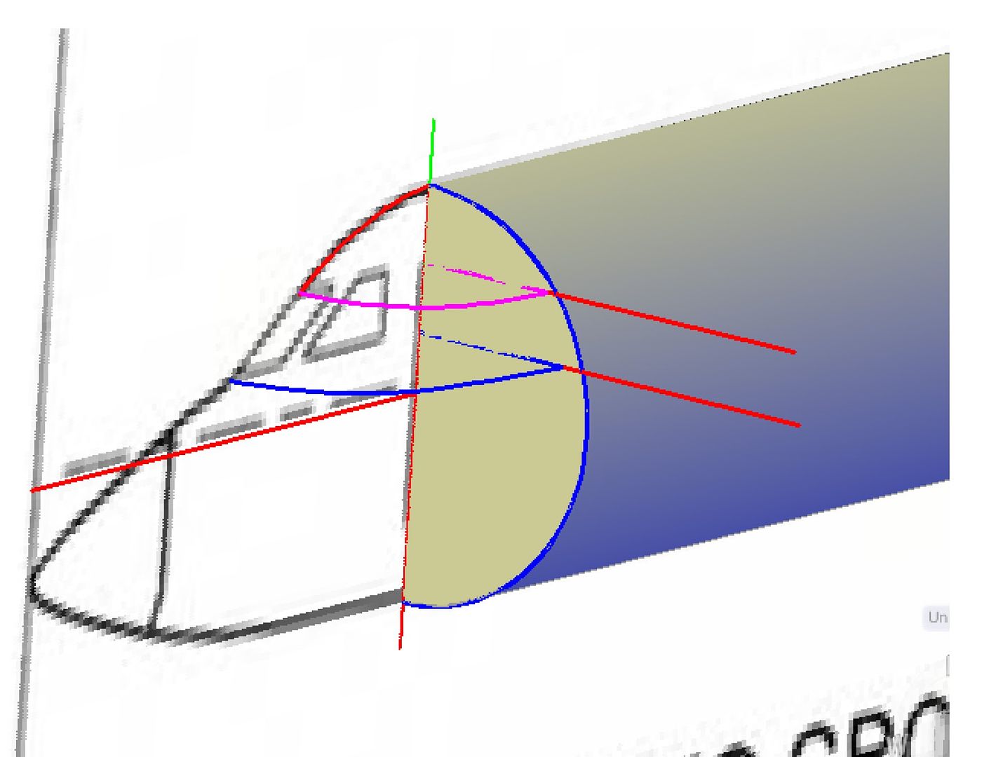
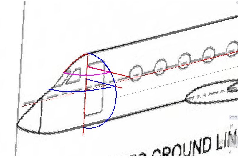
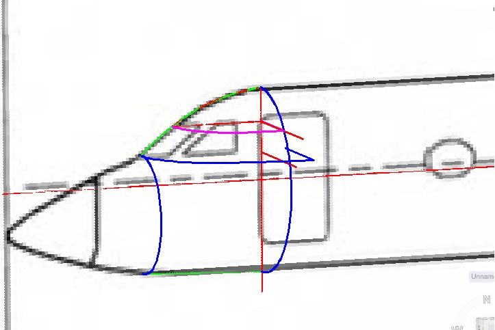
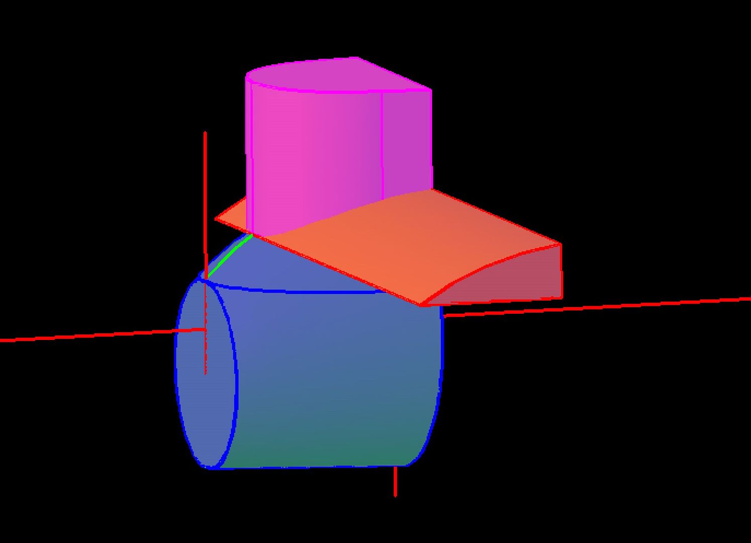
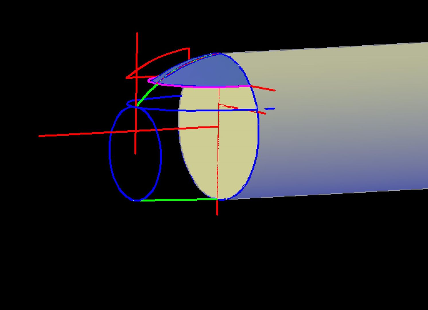
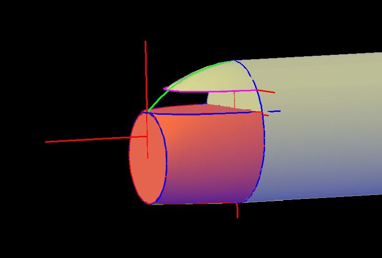
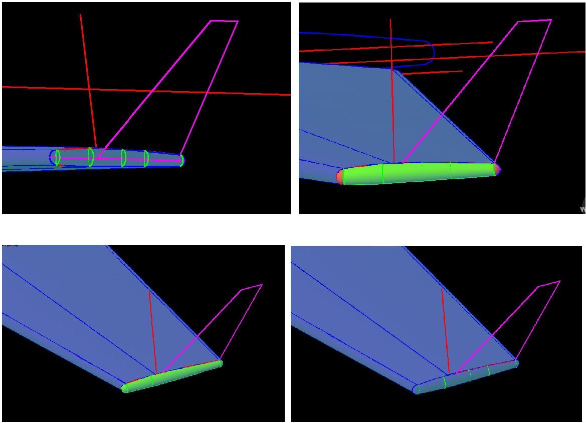
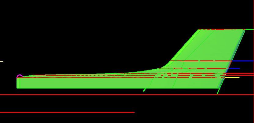
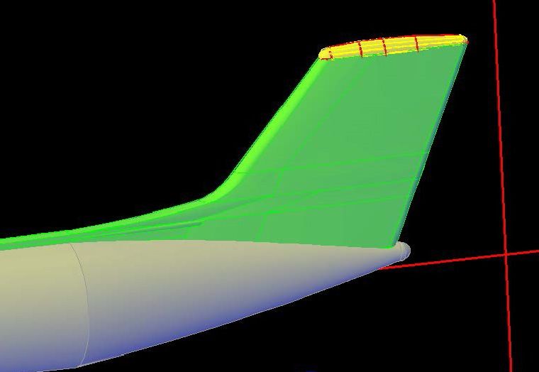
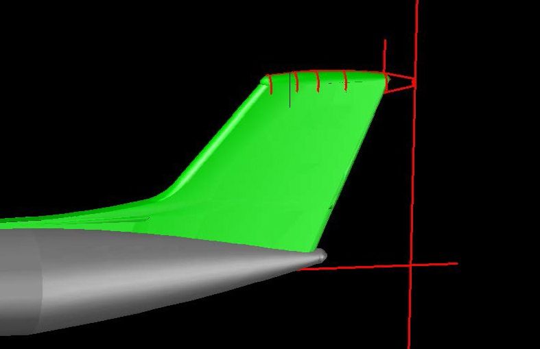
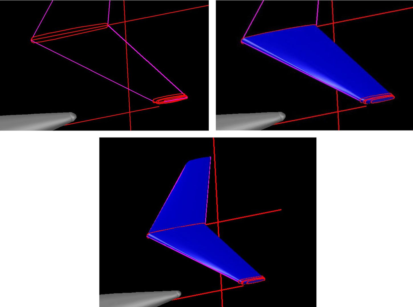
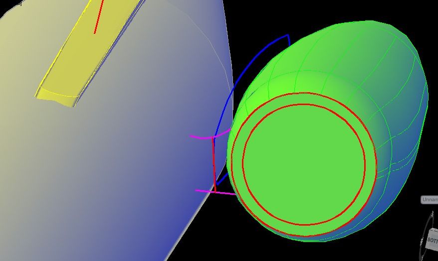
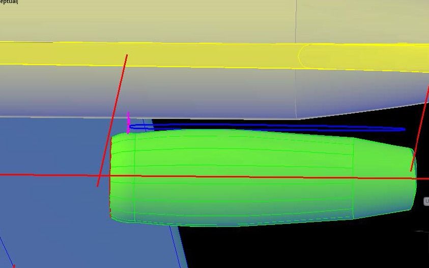
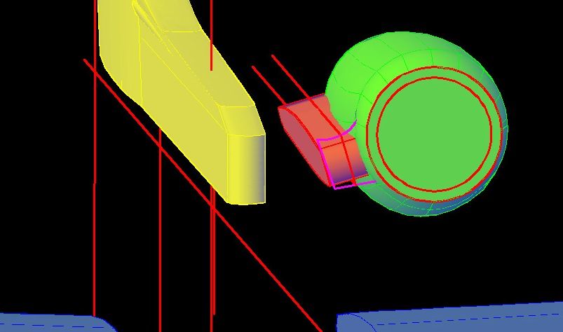
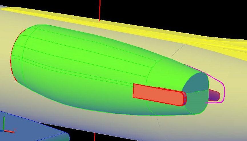
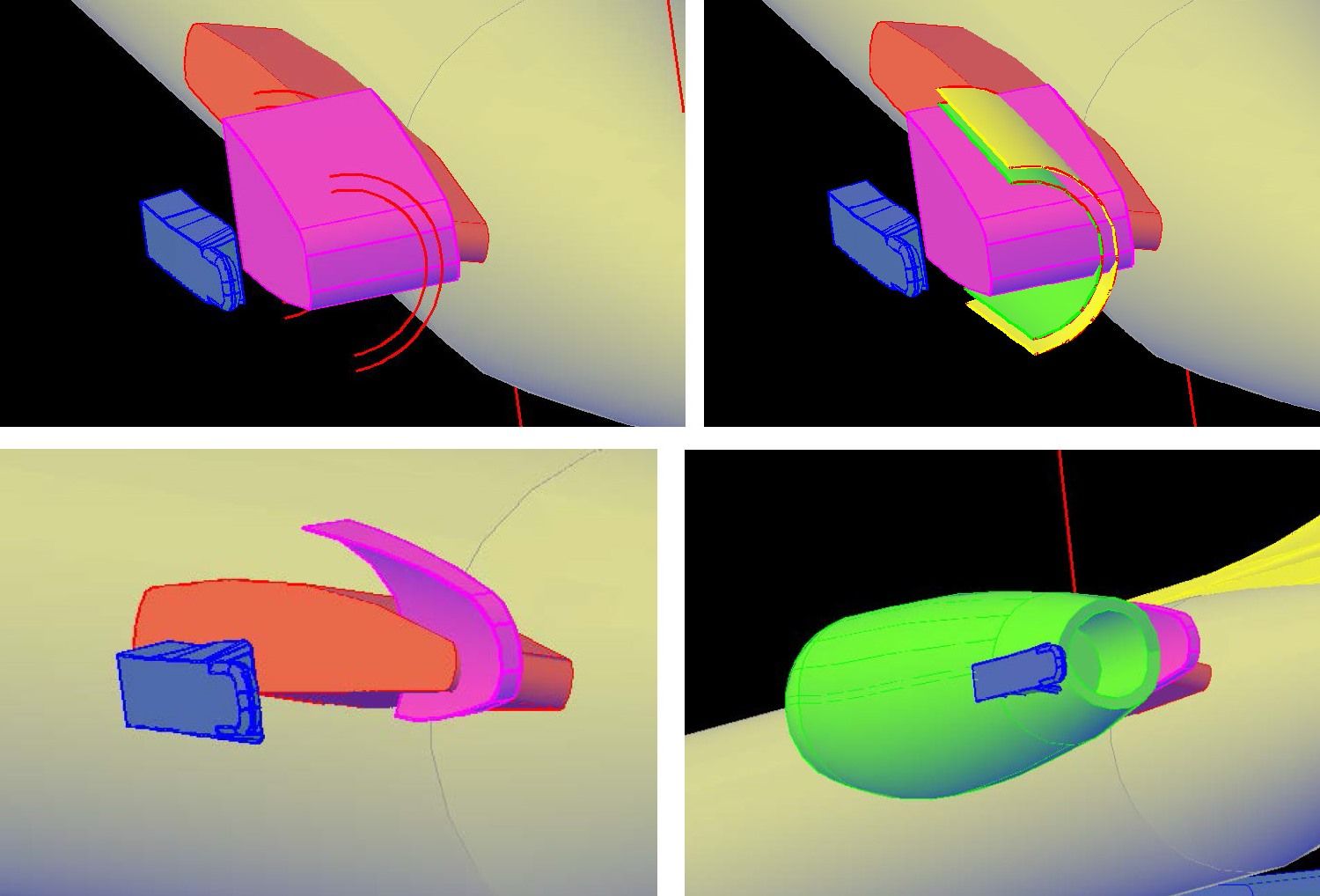
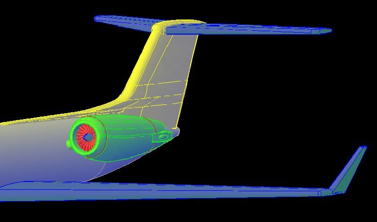
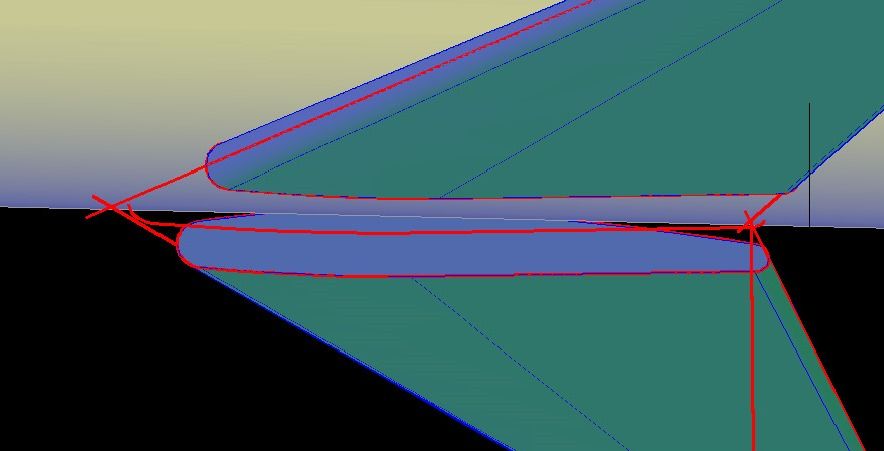
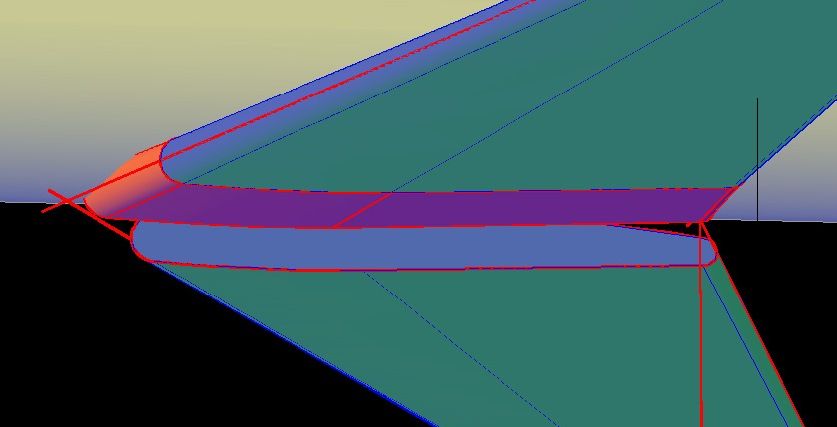
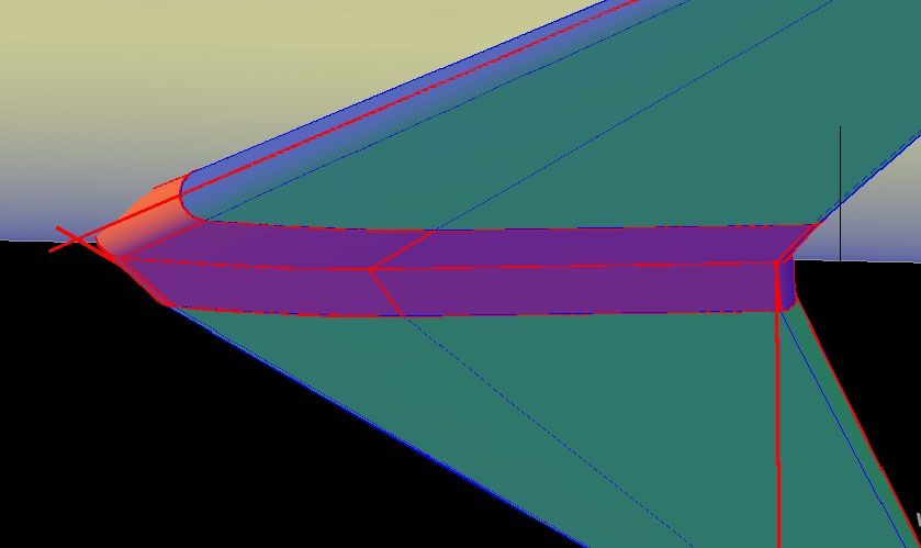
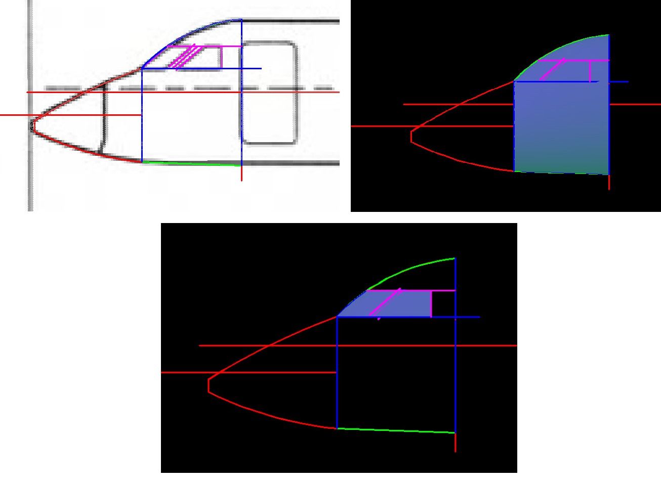
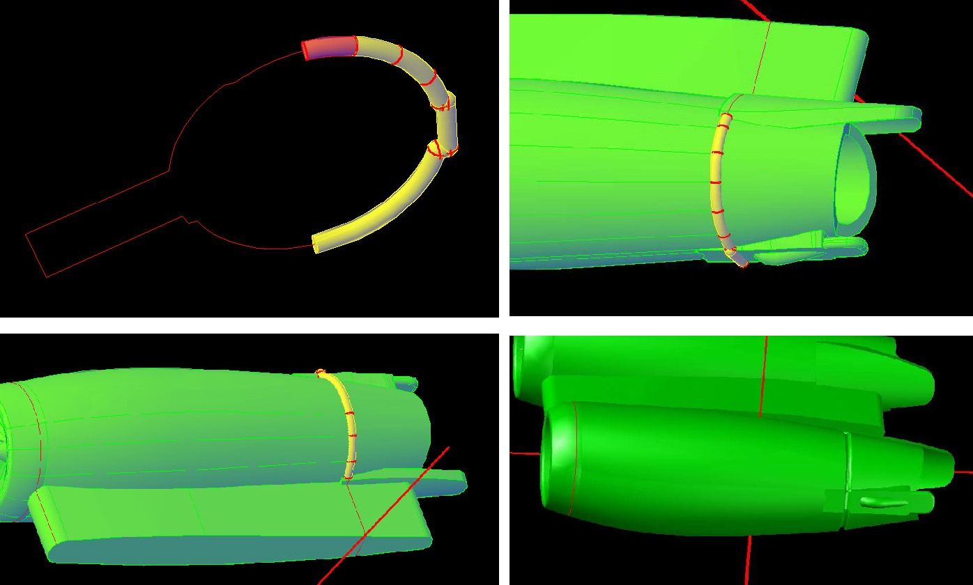
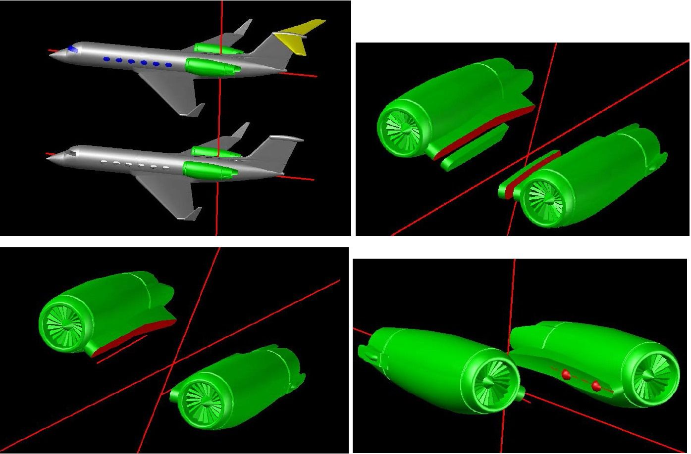
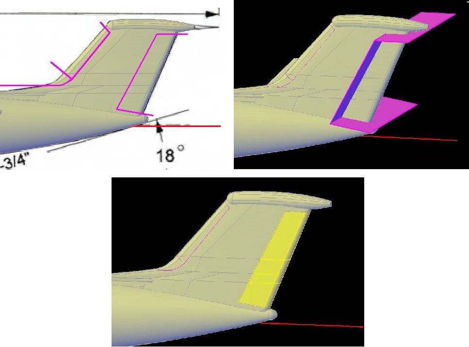
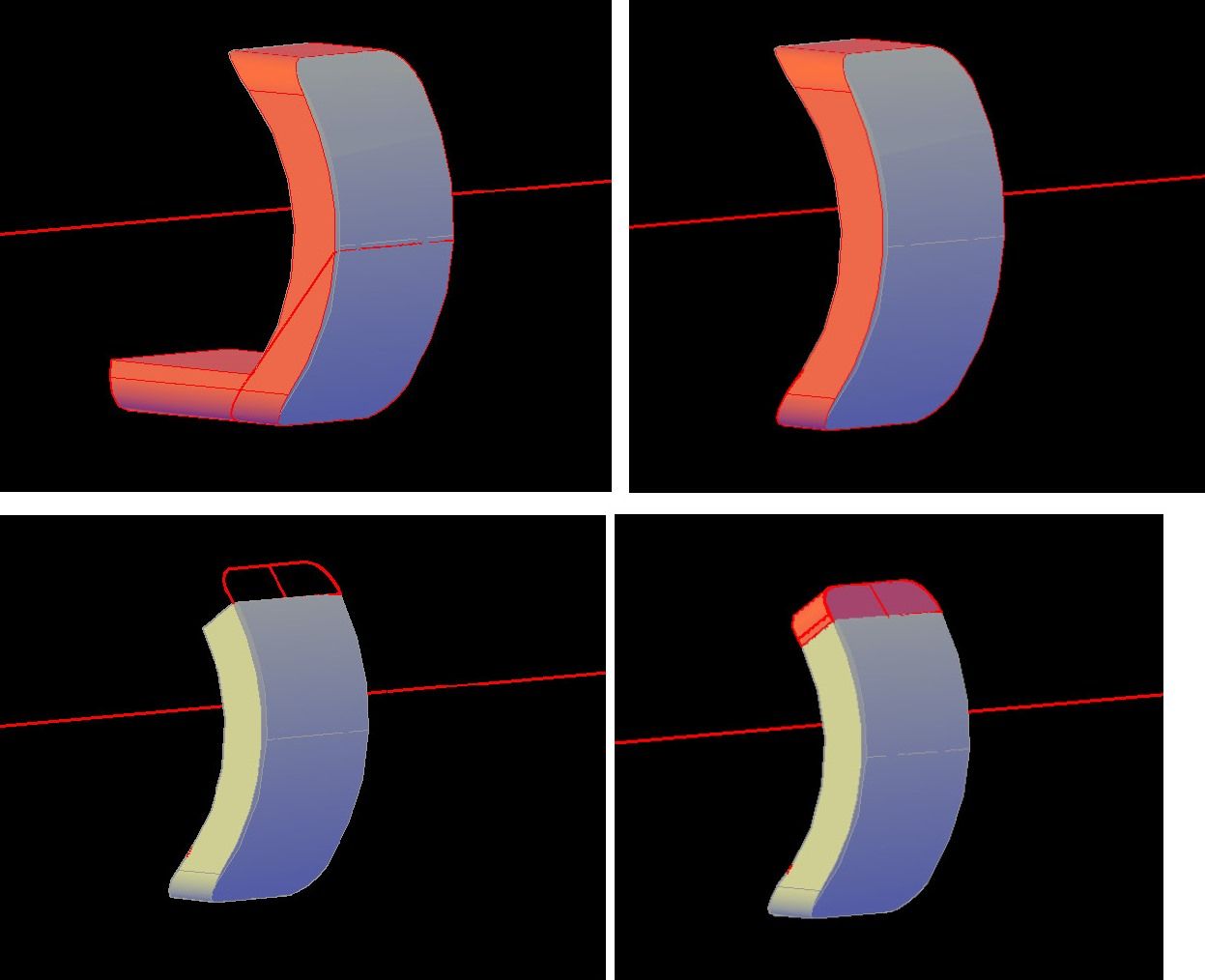
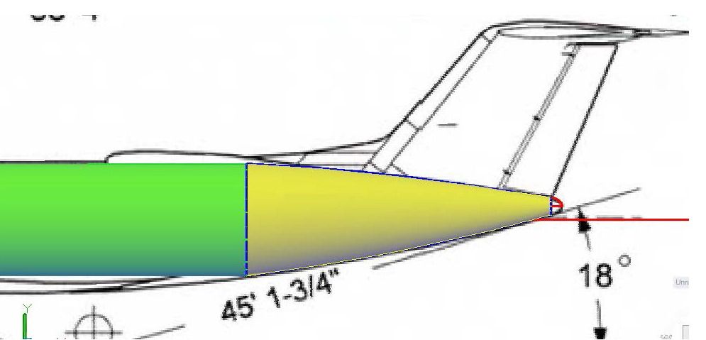
To do the aft end, I started by drawing arcs on the side view, defining the top and bottom of the fuselage to a point just below where the vertical stabilizer attaches where I drew another, much smaller circle. The arc end points are located at the tops and bottoms of the two circles. After rotating the small circle 90 degrees, I again used the Loft Command, but this time I used the arcs as guides for the loft creating a curved surface. The image below shows it before and after lofting.

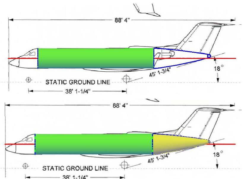
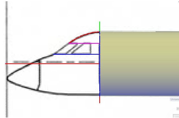
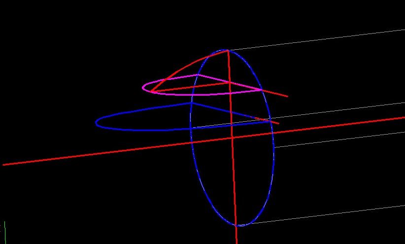
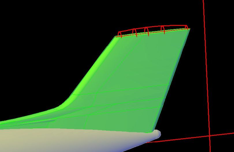
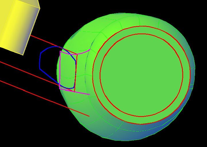
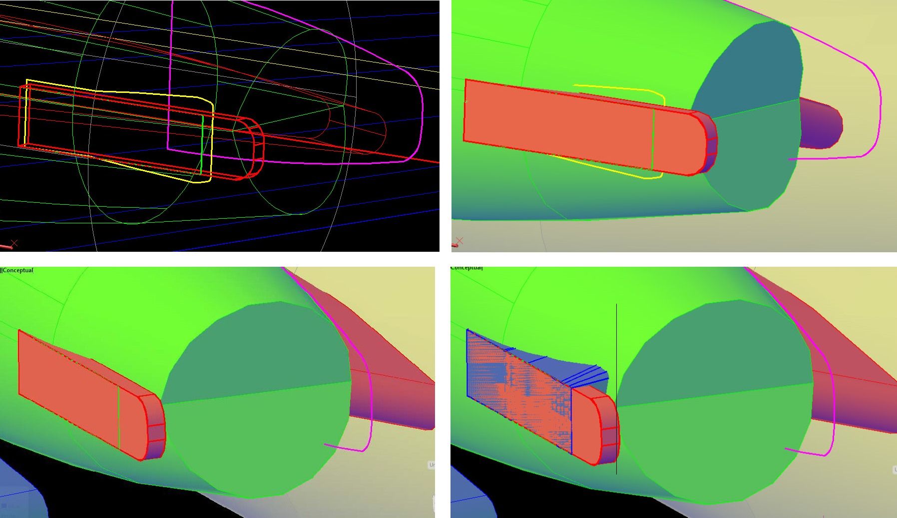
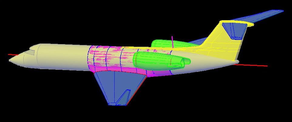
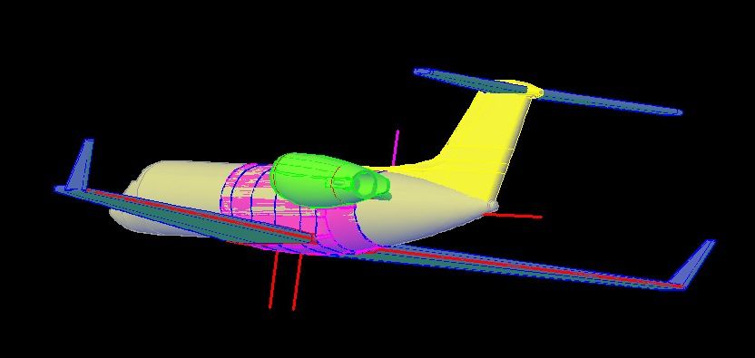
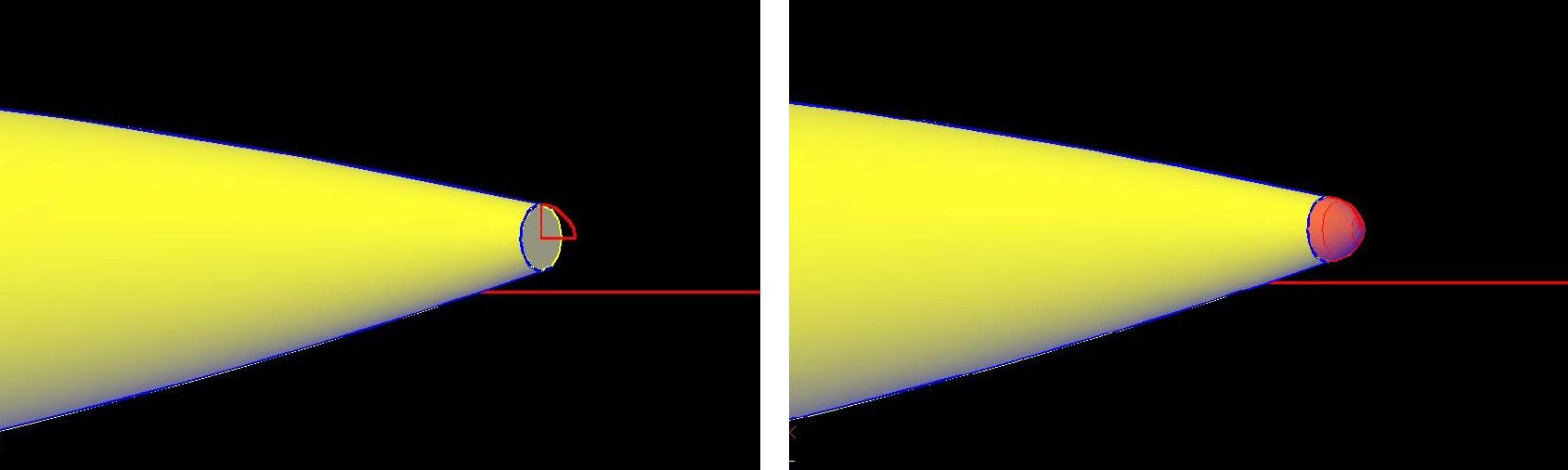
For the very end I created a polyline using an ellipse arc for the top surface, as shown in red in the image below.

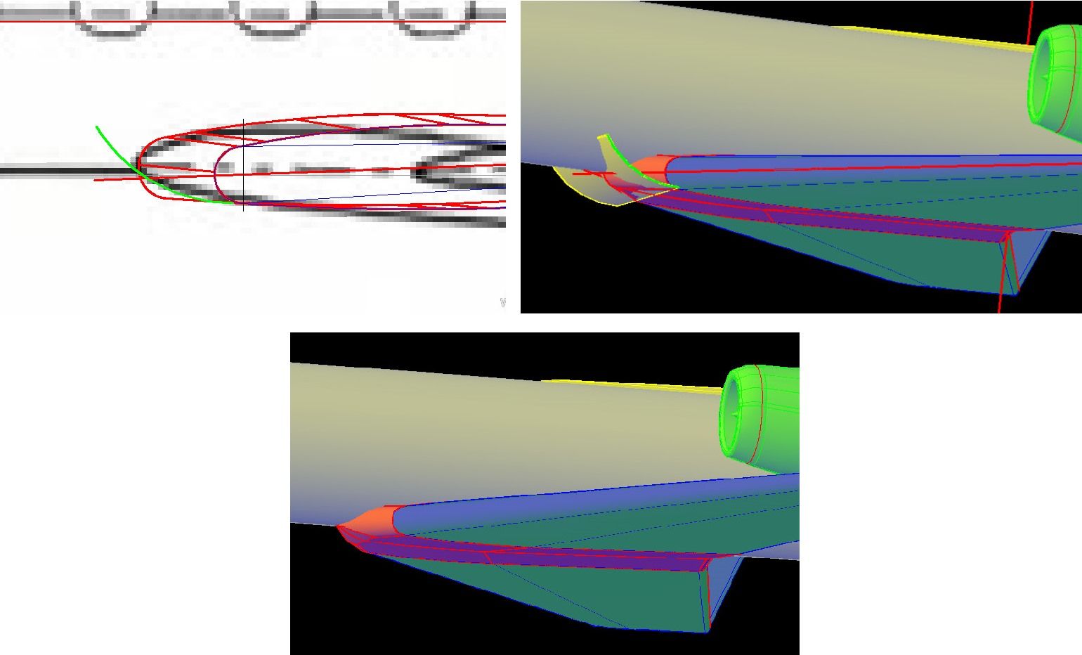
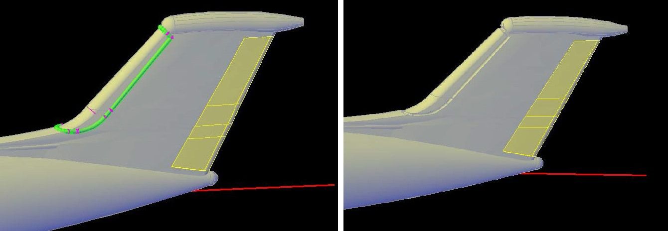
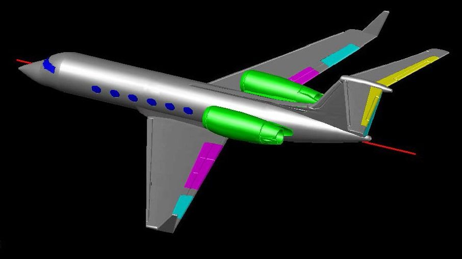
At this point, I should probably point out a couple of features about AutoCAD, the first being that it uses drawing layers that can be turned on and off. You draw on the active layer, which can be changed as desired. The second is that you can change the properties of objects, either individually, or as a layer, and you can easily change what layer an object is on. I typically draw everything on the default “0” layer, with the line thickness set to 0.03mm so that the lines I am working with stand out. I usually work in red for the same reason. When I am finished using construction lines, like the circles and arcs I have drawn, I put them on the Misc layer and turn the layer off. If I delete them they are gone forever. By doing it this way if I later need them, say because I screw something up, I can simply tirn the Misc layer back on and retrieve them.

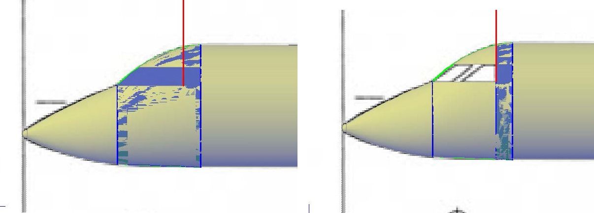
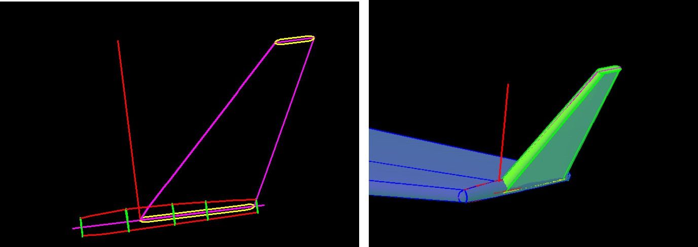
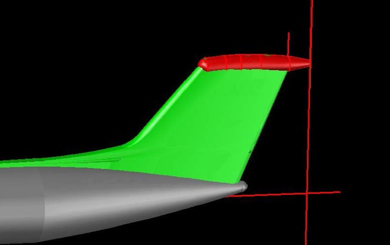
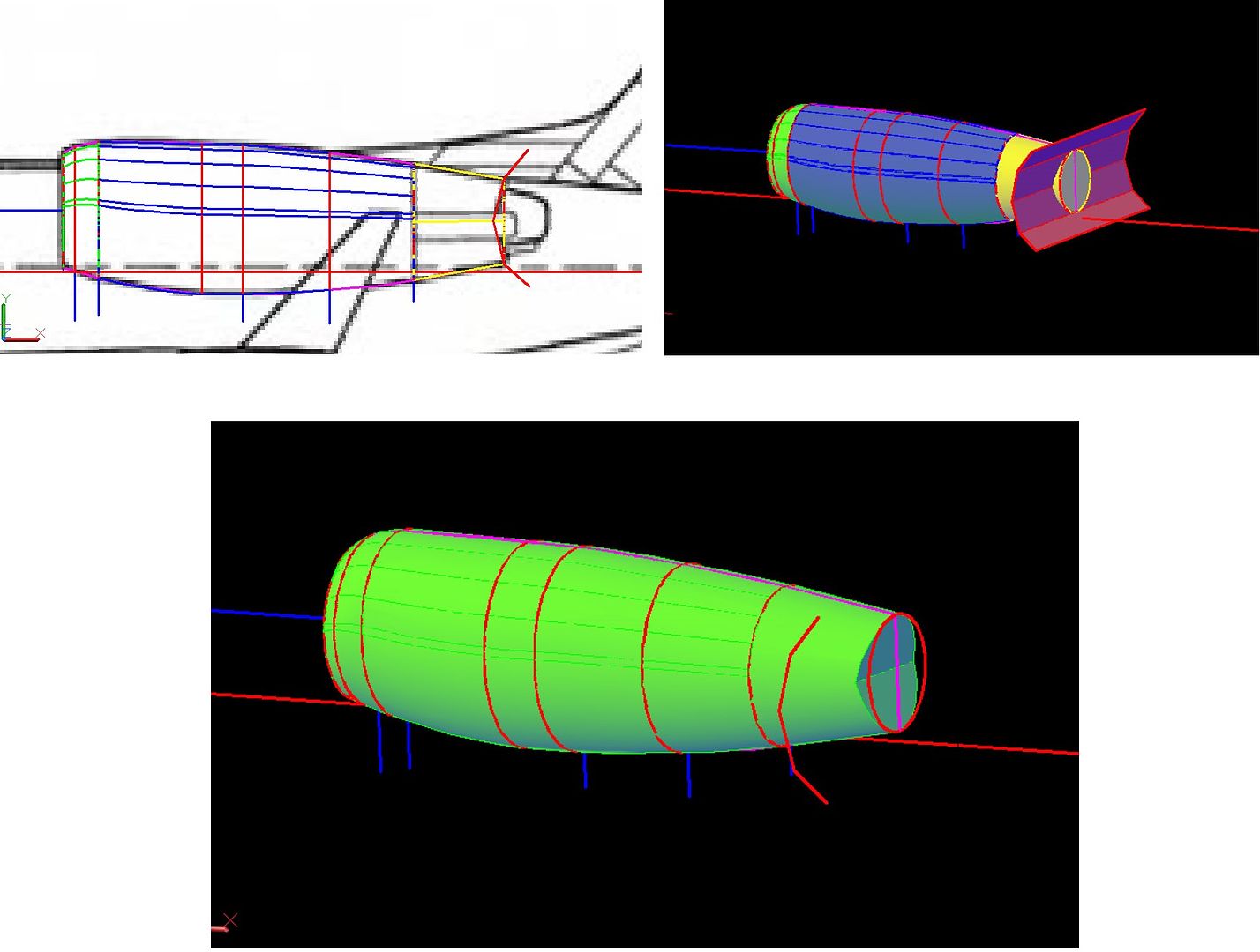
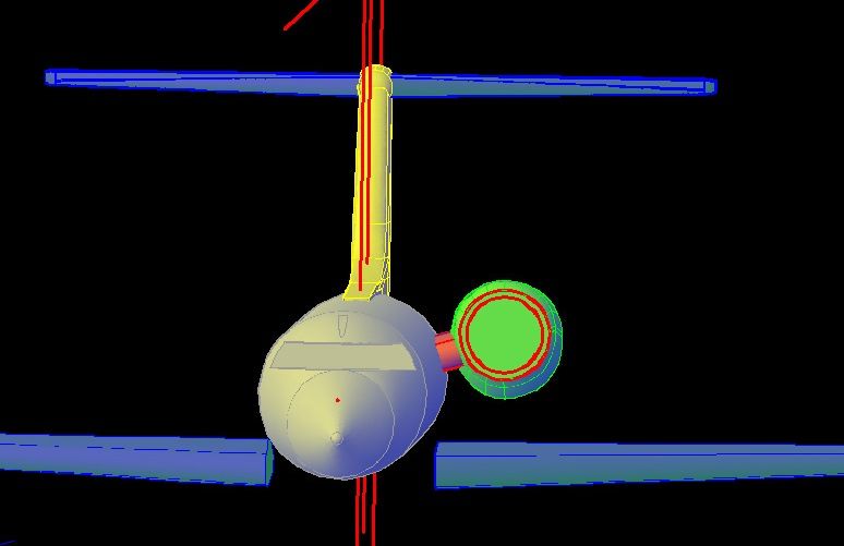
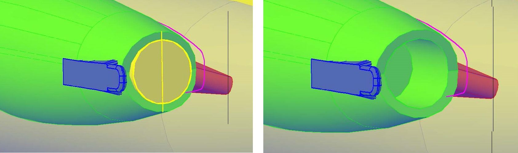
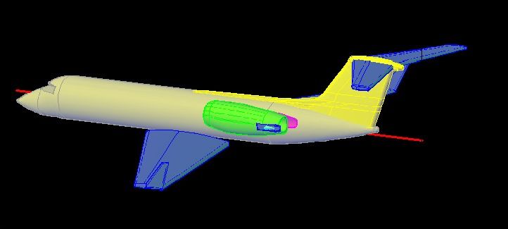
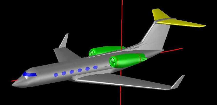
Now, the images below shows the polyline I previously drew with the model rotated and the Plans layer turned off. The image on the left shows it before Executing the Revolve Command about the central axis of the small circle.

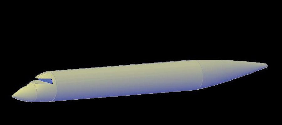
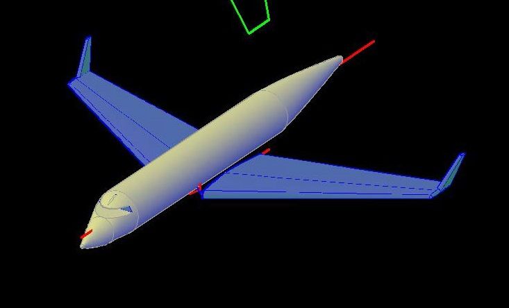
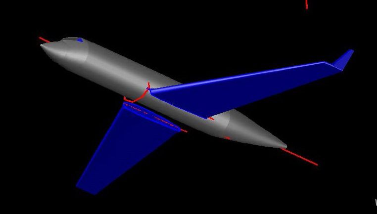
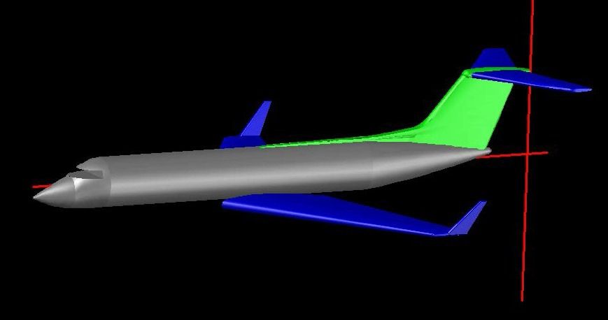
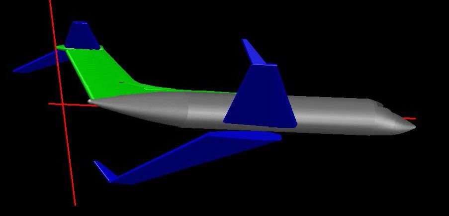
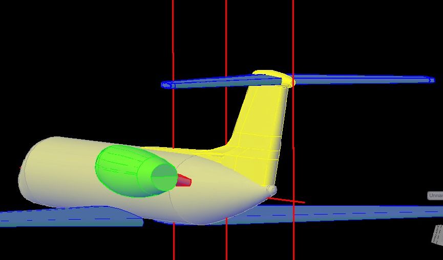
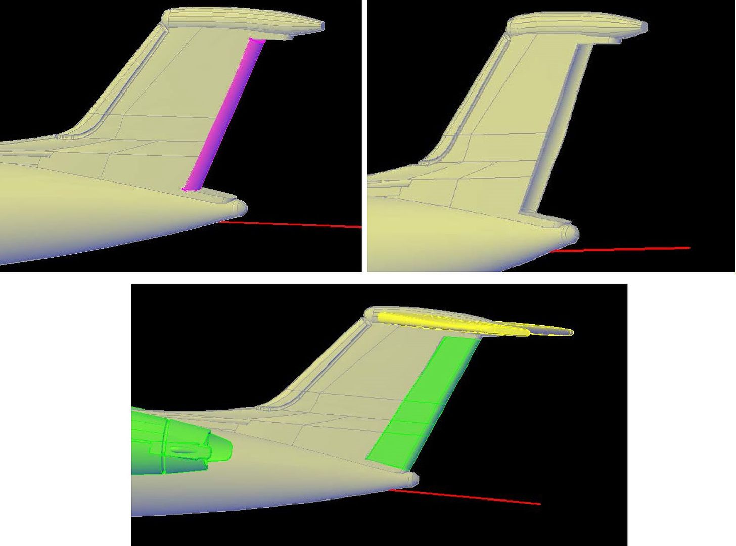
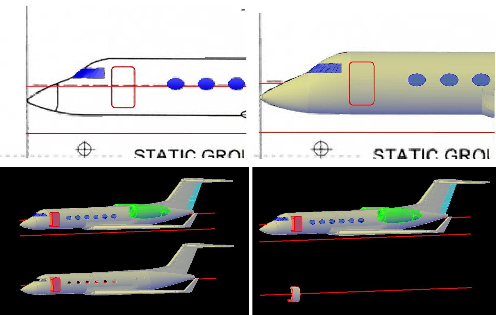
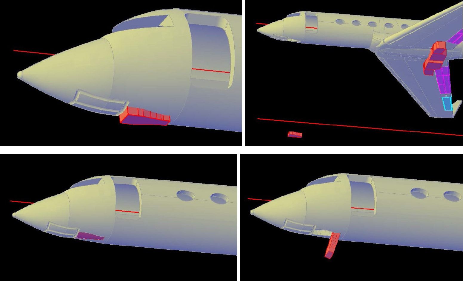
The next thing I did was use the Union Command to join the various solids. I then put it on the GIV layer and changed the color to a shade of gray.

This is a good stopping point for this post. In the next post we will make the front part of the fuselage.

CHEERS!!!

UPDATE 2

Hi again everybody!

I continued working on the fuselage this evening, starting with tracing the top and bottom of the cockpit glass line on the top view drawing (shown below in magenta and blue).

I then copied them to the side view and rotated them 90 degrees.

Looking at it at an angle though, you can see that thetracings didn’t fit quite right…

… So I scaled them up to get a better match, as seen in the image below.

There is generally more than one way to do things in AutoCad and I sometimes don’t see the best way right away, and what follows is one of those instances, but it worked. Using the tracing of the top of the cabin (in red above), I created a polyline as seen below. (This step was unnecessary as it turned out)

I then drew a circle at the front of the windshield and traced the lower lines of the fuselage with an arc and line, respectively.

I then used the Extrude Command and extruded the top outline magenta up to make a solid, and moved the unnecessary red polyline an extruded it as well. Finally, I lofted between the circles using the green line and arc as guides. The image below shows the resulting solids.

Using the Intersect Command and selecting all three solids produced the blue solid shown below.

I could have accomplished the same thing by simply slicing the lofted circles at the correct place, which is what I did for the bottom portion, as shown in the next two images. Note that I have already used the Union Command to attach the top part to the rest of the fuselage.

Putting the glass area off for later, I completed the nose section by first drawing a small circle at the forward end and tracing the top and bottom outlines with arcs, as before, as shown on the left in the image below. The image on the right shows it after I lofted the circles using the arcs as guides. You can also see the small sphere I added to the tip.

You can see in the drawing above that the glass starts forward of where the current fuselage ends, so I once again lofted between the circles and sliced it along the aft line of the windows, as seen below.

Here’s what it looks like to this point.

CHEERS!!!

UPDATE 3

Greetings All!

I started on the wings today, beginning by tracing them in the front and plan views.

I then copied them to the side view (where the model is) and rotated them 90 degrees.

These past steps aren’t completely necessary, as I really didn’t need to do the front view, but it helps me visualize things better.

Using the end of the planview tracing (green) I created cross-section for the end of the wing, using circles (0.02” dia leading edge, 0.015” dia tailing edge), and arcs to create a rough foil shape with the thickest point being0.025”. I then used the trim command to remove the inner parts of the circles and joined the remaining circle parts with the arcs to create a closed polyline.

I did the same thing with the inner part of the wing at the fuselage.

If I lofted between these shapes the wing would be flat. If I lofted it as is and rotated it to angle up like it does, it would be too short, so I moved the sections to the appropriate locations using the plans…

…Then lofted between them.

Looking at it from the different angles, you can see that my positioning, shape and size is pretty good in all views.

Next I used the Mirror command to mirror the wing to the other side.

The wings stop at the fuselage in the plan view, so you can see that some additional work will be required to merge the wings, but I wanted to finish the wing before I did that, so I deleted the uncompleted wing I just mirrored and traced the outline of the winglet.

I then rounded off the wingtip using lofted circles as you can see in the images below. Next I added spheres at the ends, joined the parts together, then joined it all to the wing.

At this point I made sections for the winglet using circles and polylines. The image on the left below shows my initial sections. Althought the top one didn’t change, I made the circle on the forward edge of the lowerone match the wing tip at that point. The image on the right shows it after I did this, and rotated the top out as shown on the plans. I don’t show it, but I also moved the winglet aft a hair to match the tailing edge of the wing.

Next, I joined the winglet to the wing and mirrored the whole wing assembly to the other side.

Next I will do the wing fuselage connection, but that is for another session.

CHEERS!!!

UPDATE 4

Good Morning All!

I made more progress on the Gulfstream IV-SP last night and earlier this morning. Since I am still not sure how to do the wing/fuselage section, mostly because I am not certain exactly how it looks, and Ron is flying today and said that he could get good me some good pictures of it, I decided to do the tail section. As with the wing, I started by making sections using circles arcs and polylines, then trimming and joining them to form closed polylines.

I then lofted the polylines to form solids. Because of the spline(?) and the relative size of the sections, I did it in sections rather than as one unit. This made for a better shape after I joined them together.

Next, I added a rounded top to the tail. I did this by first tracing the top outline from the plans, then drawing ellipses along this curve.

Then I lofted between the circles as one unit and added spheres to the ends…

…Before joining everything together with the Union Command. For many tails, it would be finished at this point, but the GIV has an extended section at the top that is wider than the sail itself. To make it, I first traced the outline of it from the plans and drew circles along the outline…

…Which I then lofted. I also added a sphere to the leading edge.

Next was the horizontal stabilizers, and once again, I started by tracing the outlines from the plans…

…Copying them to the correct location, and rotating them 90 degrees.

From here the steps are the same as before, create closed polylines and loft between them. In this case I did the four sections on the end as one part and the inner two as another part then joined them. I then mirrored to the other side and joined them together.

After moving the assembly up slightly to fit better, I am fairly happy with the way it looks. It isn’t perfect, but none of it is. At 1/350 scale, it should look pretty good though. Remember, the sail is only ½” tall at this scale.

CHEERS!!!

That is a grand “how to” and shows how your knowledge is used to create these great models.

As I cant even spell CAD (so to speak) this has shown me how you guys go about it.

Scratch building with 1’s and 0’s COOL

UPDATE 5

I’m glad you are enjoying it Steve. I thought some people might find it interesting. Yet another way to enjoy this hobby called modeling. I’m not sure if professional CAD users do things like I show them, but it is the way I have figured out how to do it on my own. There may be easier, more streamlined approaches that I am unaware of. Still, I find it fun to do, and the resulting models are nice as a bonus.

Anyway, still waiting for pictures of the wing/fuselage interface, I next started on the engines (Actually not the engines of course, but the engine cowlings, but I’ll call them that for simplicity). I first traced the outlines of the left engine from the front view plans.

I then copied these outlines to the side view. Note that the circle diameters match really well, as they should.

Next, I traced the outline of the engine on the side view plans. I then moved the large oval that I copied over from the front view back to the middle of the engine and once again it matched the side view outline. To create more sections, to better define the engine shape, I copied the oval forward and aft (3 times) and scaled them to match the traced outline at their new locations. The aft 2 sections are circles sized to match the outline, as shown in the first image below. The second image shows them after rotating them 90 degrees, and the third image shows them after I lofted them, which I did in 3 segments.

Both the plans and pictures I have seen of the aft end of the engine show it to be notched. To create the notch I traced it on the plans using a polyline, then added extensions on the end (1st image). Next I extruded the polyline to create a surface (2nd inage). In AutoCad if you extrude an open object (line arc, polyline, etc) it creates a surface. If you extrude closed objects, it creates a solid. The next step was to slice the solid, using the extruded surface as the cut line, and delete the end section (3rd image). The extensions were added so that the surface extended past the solid, otherwise it wouldn’t slice.

The image below shows the engine at this point with the fuselage layer turned on. Note the positioning of the connecting section traced from the front view (magenta).

In pictures that Ron just sent me, the connecting arm appears to be foil shaped (which isn’t surprising) so I copied the section I used to make the wing bases so that the front of it was located on the center point of the connecting section shown above.

As expected, the section was too long, so I scaled the entire section so that it would be the correct length. The image below shows I t after scaling.

Even after scaling, the section was too wide, so I extended lines back from the midpoint of the initial traced section (magenta), lowered the section to the lower line, and modified the upper portion of the section so that the high point intersected the upper section line. The image below shows the final connector section shape in blue

Next, I moved the new section perpendicular so that it was completely inside the engine and lofted it, as shown below.

The last two images show it with the fuselage layer turned on.

There is still quite a bit to do on it before I mirror it to the other side, but that is for a future post.

CHEERS!!!

UPDATE 6

I continued on the aft end of the engine housing this evening, using pictures Ron sent me earlier in the day along with the plans.

Once again, I started by tracing the items of interest on the plans. The image below shows the tracings (red and magenta) in wireframe visual style…

…And this image shows it in Conceptual visual style.

At this point I rotated the model and turned off the Plans layer to get a better look at it, and moved the shapes to opposite sides of the engine, as seen in the pictures.

Doing the outside one first, I extruded it 0.01”. Any less and I don’t think it would print and survive handling.

If you look at the pictures, you will note that the base of this protrusion, whatever it may be(?), is wider than the top (or outside end). I attempted to replicate it by first drawing a new polyline for the base (yellow), as may be seen in the first image below. I also drew another polyline (green), but only one end is visible because the rest is behind (under) the red lines. The second image shows it in Conceptual visual style. In the third image I have moved the yellow polyline inside the engine, and the fourth image shows it after lofting between the new polylines.

It was OK at this point, but I didn’t like it, because it was straight and not curving back, like in the pictures, so I tried a different approach as seen below. In the first image, you can see that I extended the red extrusion a bit, and drew a curved polyline that I copied over 0.01” (yellow). The second image shows the lines extruded, the third image shows it after slicing off both the ends of the red and blue pieces along the outside curve, and the forth image shows it after slicing the red piece along the inside curve and deleting the inner portion. I think the result is better.

Next I rounded the edges on the protruding part and drilled out the exhaust area. I did this by first extruding a circle (left image). The diameter of the circle is 0.02” less than the smallest part of the housing, maintaining a minimum 0.01” thickness, the bare minimum that will print. I then used the Subtract Command to subtract the extruded circle from the rest of the engine housing

I then moved to the item on the inner side of the housing. The inner piece is bigger and bends in multiple directions, so I had to use a slightly different approach to make it. I started it by drawing two sets of circles, both larger than the housing where they are located, and with the larger ones having a 0.01”larger radius than the smaller ones. I then cut the circles in half to form open polylines, as can be seen in the first image below. The housing was temporarily put on a Temp layer that I turned off to make it easier to see. The magenta shape is the extrusion of the outline of the object. In the second image, you can see the surfaces created by lofting between the half-circles. The third image shows the result of slicing along the extruded half-circles and subtracting the inner and outer parts, and the last image shows it with the housing layer turned back on.

At this point I decided to add the little detailing you can see in pictures of the outer feature. To do this I use another cool Command AutoCad has to offer, the Project Geometry Command, which I used to project a center line along the curve surface of the feature, as may be seen in the first image below. I then positioned circles along this line where I thought they were needed to give the desired shape. The end ones are completely inside the object. The third image shows the result of lofting between the circles as a single unit. I think the match is pretty good.

The image below shows the model to this point. I have yet to join the parts together.

CHEERS!

Good Afternoon Everybody!

Turning to the front of the engine/housing, I started by drilling out the intake area extruding the circle I had initially traced from the plans as seen in the image at left below. The image on the right shows the initial step I took to make the first stage compressor blades, which was drawing a polyline approximating the blade shape.

In the first of the images you can see that I extruded the polyline to make a “blade”. I extruded it 0.0075”. Because of the way it is supported, I can get away with going this small. In the second image, I have rotated the blade to approximate a picture I have of part of the intake. Next, I used the Polar Array Command to copy multiple blades around the central axis,as may be seen in the third image. There are 22 blades, a number that is based on the visual effect, and not the number of blades on the real plane. In the fourth image I have added the center cone using the (appropriately named) Cone Command. I haven’t joined everything together at this point, because I am waiting to see if I can get a picture of the cone. I suspect that the cone is a curved cone, and not a straight one, like I have drawn.

Here is what it presently looks like.

But it won’t look like that for long.

CHEERS!!!

UPDATE 8

Good Morning All!

With pictures that Ron sent in hand (well, on my computer), I decided to try the wing/fuselage connection, which as you can see in the pictures below, is quite complex. Trying to duplicate it was kind of a trial and error process.

I started by copying one of the wing end sections to the midpoint between the wings. I originally positioned the leading edge at the intersection of the forward edge lines, and scaled the section up so that the tailing edge met the intersection of the wing tailing edge lines, but then to match the plans, I moved the section back a bit as may be seen in the image below.

I then lofted between the new center section and the left wing end section…

…And mirrored the resulting solid to the other side.

The first image below shows the results of the previous steps looking at the plan view in wire-frame mode and the plans layer turned on. You can see that even though I moved the center section back a bit the leading edge bulges below where the surface should be, due to the way I designed my wing sections for printing purposes. To fix it, I tried drawing a polyline along where the surface should be, and extruded it, as shown in the second image. The third image shows it after slicing the wing connectors along the resulting surface and deleting the lower parts.

Looking at it from a distance, it looked better…

…But it wasn’t close to right, so I tried another approach, as shown in the image below. The ends are the circles of the fuselage. The other sections were created using fuselage circles for the top part. The bottom part for most of the remaining sections was made using a modification of the section shape traced in back in Update 3 (red). The modification included adding an ellipse on the bottom and extending the straight side sections so that the midpoints on the bottoms lined up with the section tracing of the fuselage underside (magenta). The second section from the right was made using the fuselage circles for both the top and bottom, joining their ends with lines, deleting all but the outer parts and joining them to form an oval. Obviously, creating the items shown in the image took many steps that I have omitted.

The images below show the results after lofting the circles and polylines in 3 segments. One segment had to be forced to the correct shape using the magenta guidelines seen in the previous image.

I was fairly happy with it, so I joined the new objects, fuselage and wings together using the Union Command.

The aft end looked pretty good, not perfect but I think it will work. The front was another matter. It was way wrong.

So, I went back to the drawing board and redid the forward end, adding an extra section and moving the circle forward a hair. The images below show the sections before and after lofting and the model after joining everything together.

Although it isn’t perfect, I think it is fairly close. At any rate, it is as close as I think I can get it. It might not work at 1/72 scale, but at 1/350 (or even 1/144) I think it will be fine, and if not, a little sanding will do the trick.

On another note, you may have noticed that I joined the engine housing parts together. Ron sent me a cool schematic of the Tay Turbofan Engine and the cone is straight and not curved, so I decided I was happy with it, and joined everything together and mirrored it to the other side.

CHEERS!!!

UPDATE 9 – 3/15/2014

Good Morning Again Fellow Modelers!

This morning’s adventure began with the cockpit glass, which will be printed in clear plastic. The images below show the steps I took to make it. As is typical, I started by tracing the relevant lines on the cross-section defining the glass areas, as seen in the first image. In the second image, I have used the same circle sections and guidelines that I used to make the fuselage to make a solid object, that I then sliced as shown in the third image.

In the short time I have been making CAD models for 3D printing, I have tried various ways to do the windshields and canopies. At 1/350 scale, I find it best to recess the glass within the frame and print the frame and/or supports in clear plastic along with the glass. That is the way I decided to do the GIV.

The images below show the resulting sliced object. In the first image you can see where I have drawn numerous small lines on the surface. (Actually I did one, copied along one side, rotated them individually and then mirrored them to the other side). These lines are 0.004” long and extend roughly parallel from the surface edge. The end points of these lines were then joined to make a closed polyline. I did the same thing on the underside, although it isn’t shown. In the second image, I have sliced the solid along the forward and aft edges of the side window frame lines, and deleted the aft portion. You can clearly see the two polylines I just created, which I lofted as seen in the third image. In the fourth image, I have sliced the initial solid (blue) along lines offset 0.005” from the center line creating a 0.01” wide center support beam.

The final image shows the model with the new windshield and windows.

CHEERS!!!

Greetings All!

At this point, it was time to hollow out the interior. I only wanted to hollow it out down to the cabin floor, so the first thing I did was import and scale a drawing showing the cabin layout and traced the floor from the side view, as shown in the first image. The next step was to define the area to be cut. To do this I first copied the circles, used to create the fuselage, down out of the way. I then reduced the diameters of the circles by 0.05”, to provide 0.025” thick walls, which is as thin as I have been advised to make larger objects. The second image shows the resulting loft, that I did in two parts and joined together to form one solid. It seems to me that the floor was too high, so I imported a drawing I found in the stuff Ron sent me that shows the floor level and scaled it to size. The third image shows the floor level in the drawing (blue). This seemed better so I used it as the slicing line for the solid as seen in the fourth image.

The next steps aren’t easily seen without using wireframe and even then I think it might difficult to see it, so suffice it to say that I copied the new sliced shape up inside the model and subtracted it. I then copied it up there again and subtracted it from the windows I made earlier. The images below show the result, with the clear piece moved forward for viewing.

Next I did the side windows. The images below show the tracings I made from the plans with the GIV layer turned off (top) and on (bottom)

I then extruded the window tracings through the fuselage and copied them and the fuselage (and the centerline) down a bit, as shown in the first image below. Next, I used the Intersect Command, selecting the fuselage and the first window extrusion, the result of which is seen in the second image. By repeatedly copying the fuselage down and using the intersect command I was able to create all 12 windows (6 on each side), as shown in the third image, that also shows the fuselage after I have used the Subtract command to create the window openings. The fourth image shows the windows copied to the openings.

Here is what it looks like in Realistic Visual Style.

I have stuff to do now, hopefully I can do more tonight.

CHEERS!!!

UPDATE 11

Hi Guys!

In the last session I had made the windows. I started my next session by filleting the inner edges at 0.005” to make installation easier. I was going to chamfer them, but the angled/curved shapes wouldn’t allow this. The fillet should work just as well.

With that completed it was time to start adding surface detail to the model. The first detail I decided to add was an etched line to separate the painted and aluminum surfaces of the engine housing. To create etchings on my models, I extrude 0.01” diameter circles along the surface and subtract them, leaving a cut out that is 0.01” wide and 0.005” deep at its deepest point. The images below show the steps I took to accomplish this. In this case, I projected the 0.01”radius circles along the lines I had previously projected on to the surface of the housing. The method requires repeatedly moving and rotating the coordinate system for proper orientation of the circles, which are drawn perpendicular to the projected lines. The first two images below show it after I had drawn the first circle, loft it, reoriented my coordinate system, and drawn the next circle. The next two images show it in progress as I add segments to the extrusions. Although it isn’t really visible in the images, I add 0.0102” spheres at locations where the lines to be etched meet at angles, to assure that there aren’t gaps between the two “tubes”.

In many cases it is easier to turn the layer of the part being etched off for better viewing, as seen in the first of the images below. The second and third images show where the tube meets the extensions I had added earlier. The end circle on the inner one was rotated slightly off vertical so that the tube didn’t intersect the extension. The fourth image shows it after I executed the Subtract Command and subtracted the tube from the housing.

I repeated the process for the ring at the forward end of the housing. On the side near the fuselage I extruded the tube through the support arm, as may be seen in the second image. To fill the hole I used my original tracing, which I retrieved from the Misc layer, extruded it into the housing and used the Union command to join them together.

When I finished it, I deleted the old one on the other side of the fuselage, and mirrored the new one there, as seen below.

I had been considering whether I wanted to attach the engines to the model or make them as separate parts to be attached when the model is built. I decided to make them separate. I first copied the airframe and engines down to my temporary reference line as shown in the first image. I next subtracted the copied airframe from the copied engines as seen in the second image. Note the two “shims” between the two engines. These would be inside the cabin, so I needed to remove them. In AutoCad though, even if a part has been split, the two parts are still connected as an object. To separate them you have to use the Separate Command. Then the unwanted parts may be deleted as shown in the third image. At this point we have a housing that will fit perfectly on the surface of the fuselage, provided it is positioned accurately. To assure that the parts are located properly I made “pins” and recesses for attaching them. The fourth image shows 0.032” diameter spheres drawn on the centerline of the interface surfaces of the engine supports.

These spheres were subtracted from the engines to create recesses for receiving the “pins” added to the fuselage as seen in the first image below. At this point the engines were moved up to the model and 0.03” diameter spheres were drawn at the centers of the spheres used to cut the recesses. The second image shows it with the engine layer turned off temporarily. The third image shows the model with the pins joined to the model with the Union Command.

The last image shows the model with the completed engines.

UPDATE 12 – 3/16/2014

Good Morning All!

Continuing with the detailing last night I traced the needed lines from the top view and side view plans. The image below shows the plan view tracings…

…And the first image below shows the side view tracings on the tail. The lines on the leading edge were projected onto the surface, and the aft line, for the rudder, was extruded through the surface, as shown in the second image. The third image shows it after slicing, creating a new part for the rudder.

The next two images show the leading edge surface “tube” I created as I did with the engine on the left and the results of subtracting it from the tail.

Returning to the rudder, I added a rounded surface to the leading edge by drawing circles with the same diameter as the width of the rudder ends and lofted between them. I also extruded the lower circle down a short distance and joined the two solids, as seen in the first image below. I then sliced the solid even with the ends of the rudder (second image) and joined the solid and rudder together (third image). With the rudder curved, I had to modify the airframe to accommodate it, so I increased the diameters of the circles by 0.002” and repeated the first two steps to make the forward edge tube, and slice it.

In the first of the images below I have turned the airframe layer on and the rudder layer off so you can see the tube that I subtracted from the airframe, as seen in the second image. The third image shows it with the rudder layer turned back on.

With the rudder completed, I turned my attention to the horizontal stabilizers. The first image below shows the plan tracings, with the plans layer turned off. You can see that I have copied the tail parts and center line down to just above the stabilizer on the side view. In the second image, I have rotated them 90 degrees. The third image shows it from the top, as does the fourth image. The difference between the two, although it is difficult to see is that I had to move the inside line on the forward edge polyline out a little so that the I wouldn’t cut into the tail when I did the etching.

The first image below shows it after I extruded the aft lines to cut out the elevators and projected the forward lines for etching. Note that I also projected some lines onto the elevators themselves. In the secondimage I have sliced the elevators off, creating two new parts. The third image shows the surface “tube” on the right elevator. Note that I joined the stabilizers to the airframe at this point. The fourth image shows it after I have made and subtracted the tubes from the leading edge.

In the first image below, I have subtracted the tube from the right elevator and given it a curved leading edge as I did with the rudder. The second image shows the slightly larger tube I made to cut out the curve in the airframe, and the third image shows it after I subtracted it. The fourth image shows it with the elevator layer turned back on.

Here is what the model looks like at this point.

Now to the wings.

CHEERS!!!

UPDATE 13 – 3/16/2014

Good afternoon everybody!

Now for the wing detailing. The image below shows the wing tracings I showed in a previous post after they have been copied and rotated to the model.

In the first image below, I have projected the leading edge lines onto the model, as well as some lines on the aft end. The second image shows the surface tube as I made it and mirrored to the other side. The third image shows it after I subtracted the forward tubes, created the aft tubes and mirrored them to the other side. The fourth image shows it after I subtracted the tubes and extruded the lines for the flaps and ailerons.

The first of the next set of images shows the model after I have sliced the wing along the extruded surfaces. The second images shows the lines for etching the flaps, and the third image shows the flap and aileron after I added the rounded leading edge and drawn the tubes for cutting out the section in the wing, as shown in the fourth image.

The final image shows the current state of the model.

CHEERS!!!

UPDATE 14

Hi Again Everybody!

The detailing continues as I decided to do the door next. Once again I started by tracing it on the plans, as seen in the first two images below. Actually it is a rectangle with the corners filleted at 0.0175”. Next, I extruded the door into the fuselage and copied both the extruded door and airframe down to my temporary reference frame, as seen in the third image. I then used the Intersect Command as seen in the fourth image.

The first of the images below shows the door after I used the intersect command. You can see that it includes part of the floor, which I don’t want, so I sliced it off, as seen in the second image. Because the door cut sliced through the fuselage at an angle, the top of the door was not square at all, so I drew a polyline square with the top and sliced the top of the door off, as shown in the third image. I then extruded the new polyline to the thickness of the door.

After I joined the newly created top to the bottom of the door, I copied it up to the model (first image) and subtracted it (second image). In the third image I show it rotated roughly in the position it would be open, minus the ladder of course. That is for another day.

With the door complete, I turned to the gear doors, starting as usual by tracing them from the plans (first image). The difference this time is that I had to import a different set of plans that showed them. After tracing them on the new plans, I copied them to a center line I positioned beneath the fuselage as shown in the second image. Ron says that the forward gear doors are closed when the gear is down, opening only long enough for the gear to lower, then closing again. Because of this the front door outlines were projected onto the airframe surface, as shown in the third image and a surface tube was created, as shown in the fourth image. The latter two images also show the rear forward gear door outline extruded into the surface 0.025”.

The first image below shows the model after I subtracted the surface tube from it, and again shows the extruded rear door. At this point I copied the airframe and the extruded gear door down to my temporary reference frame and used the Intersect Command to create the gear door as shown in the second image. I then moved the door back up to the model (third image) and rotated it to roughly the position it will be when the gear is down.

For the rear gear doors, Ron says that the inner ones close after opening and that the outer ones are part of the gear, so I projected the inner ones onto the airframe surface, created one of the surface tubes, mirrored it to the other side and subtracted them. The outer doors were extruded into the airframe (actually the underside of the wings) 0.025” and the same steps just described for the forward gear door were followed to cut out and create the doors. The first three images show the steps and the last image shows the closed doors.

The image below shows all of the gear doors in the down position, just waiting to have gear attached.

CHEERS!!!

UPDATE 15 – 3/17/2014

Greetings All!

The next thing I did on the Gulfstream IV was the forward landing gear. To do it, I used the plans and several photos, including the three shown below.

Using the plans, I first traced the outline of the circle (first image). Then, I copied a wheel I have from previous models and sized it properly, as seen in the second image. I then returned to the plans and drew a box around the wheels on the front view, which I copied and rotated to the model, as shown in red in the third image. I moved the wheel to one side of the box and mirrored the wheel to the other side, as seen in the fourth image.

Next, I created an axle between the two wheels, as seen in the first image below. In the second image, I have started the shaft that holds the wheels. The red line shown in the images was copied from the plans. In the third image I have drawn the lower bracket seen in pictures, and in the fourth picture I have added the upper bracket and extended the wider part of the shaft. Note that I also rotated the gear door a bit to make it match the pix better.

I continued working my way up the gear adding features to match the pictures as closely as possible. Note the arms running from the gear door to the shaft and the bend at the top of the shaft. At this point I joined the upper parts of the gear together as seen in the second and third images. The fourth image shows the gear with the airframe layer turned off.

The reason I didn’t attach the lower portion was because I wanted to make two versions of the gear. One with the gear retracted and loaded as if on the runway or tarmac (that I just made), and the other retracted, but with no load on it as when in-flight. I plan on building mine on the tarmac, but together with just the gear doors, other modelers will have three options on how to display the gear. Using the gear I just made, I lowered the wheels and lower bracket down a distance that looked about right. I then drew circles that the brackets would revolve around. In the first image below, I have already rotated the lower bracket from its previous position to one of the two intersections of the two circles. I then rotated the upper bracket to the same intersection and joined everything together, as shown in the second image.

The two images below show the two versions of the gear, after I had added the lights to it.

Tomorrow, well, later today, I will start on the rear gear, if time allows.

CHEERS!!!

UPDATE 16

Hello Everyone!

Looking at pictures of parked GIVs I noticed that in some pix the gear doors that I etched into the airframe are down as seen below.

After some thought, I decided to modify my model to allow the modeler to build it in this configuration if desired. To do this I first went to the CAD file of the model I saved prior to starting the detailing, and copied it to the current drawing, as seen in the first of the images below. I then drew an open polyline on the nose to encompass the etched area for the forward landing gear, and copied it to the old model too, as seen in the first image below. I then created a closed polyline to encopasse the etchings for the right and left gear, and extruded it into the airframe, and copied it the the old model, as seen in the second image. I then sliced both airframes at the open polyline, and kept both parts of the slices. I then used the intersect command on the lower model and the main landing gear area solid I just made, leaving just the 2 unetched parts seen at the bottom of the third image. Next I subtracted the solid from the current airframe and deleted the forward gear notch, as seen in the fourth image.

In the first image below, I have copied the unetched parts up to the airframe. In the second image I have joined them to the model, and in the third image I have extruded the door tracings into the airframe in preparation for creating the new doors.

The next thing I did was copy the airframe and extrusions down to my temporary reference line, as shown in the first image below. Next I used the Intersect command to create the four doors (repeatedly copying the air frame down each time), and subtracted the solids from the airframe. The resulting shapes and cutouts are shown in the second image. The third image shows it after I copied the solids up to the airframe.

Beginning with the nose gear doors first, Ifirst made the closed doors, by joining the two solids, projecting a line down the middle of it and creating a surface tube (first image) and subtracted it (second image). For the doors down version, I rotated the doors 90 degrees about their edges and lofting between two closed polylines created a solid from the tops of the doors to the bottom of the cutout, and then added this solid to the doors as seen in the third and fourth images.

The rear doors had to be modified slightly due to the fact that I don’t have the shape of the underbelly quite right, which made the doors have a funky shape when down. Sorry, I didn’t track this process, but the first image shows the modified doors. The second image shows the tabs I added for proper positioning of the doors. The third images show the 0.001” larger spheres drawn on the tabs, and the fourth image shows it after these spheres have been subtracted from the airframe (Door layer turned off)

Although I don’t show it, I also added matching tabs to the closed doors. Next I will do the rear landing gear. When I finish the modeler will have 4 options for displaying the model; gear up, gear down and extended, gear down and compressed with doors closed, and gear down and compressed with doors open.

CHEERS!!!

UPDATE 17

Hi guys and gals,

To start the main landing gear, I began with the wheels, using the pix below, among others, and the plans.

In the images below you can see where I traced the wheels and linkage on the plan sheet that has them (top) and copied it to the model plan set (bottom). You might notice that the wheel is slightly ahead (0.02” or about 7” on the real plane) of the one shown on the plans. The reason for needing to move it is unclear, but, although I didn’t mention it at the time, when I traced the gear openings, copied them, and rotated them, they intersected the flaps. To fix this issue, I had to move everything forward. I don’t know why this happened. Everything else has been spot on.

Next, I went to my wheels drawing and copied one of the wheels to the GIV drawing as shown in the image at left, below. The wheel was too small, so I scaled it up to match the wheel tracing, as seen on the right.

With the wheel the correct size, the next thing I did was try to replicate the ones in the pix. To do this I first filled the open area of the copied wheel as seen in the first two images below, by extruding a circle into it and joining it to the wheel. I then created a new, wider, and less deep cavity, and extruded a smaller circle for the axle. Next, I added a sloped hub by lofting different sized circles, as seen in the fourth image.

Similar treatment was given the interior side of the wheel. The recess was created first, as seen in the first two images, because this side of the wheel I copied was not recessed like the other side was. In the third image I have trimmed off the axle and mirrored the sloped hub, and in the fourth image I have joined all of the components together.

To complete the wheel I tried to create the recess pattern seen between the hub and rim of the wheel. I did this by creating a closed polyline with two lines and two circles, and extruding it 0.005” into the lowest surface, as seen in the first image below. Next I used the Polar Array Command to make 8 of them evenly spaced around the center of the wheel (second image). After copying them to the other side of the wheel I subtracted them as may be seen in the third and fourth images.

With the wheel completed, I decided to add to my wheel drawing, upping my wheel collection to six, as seen below.

In the next session, I will continue on the landing gear.

CHEERS!

UPDATE 18

Good Afternoon Everybody!

Before continuing with the main landing gear, I first made some modifications to my wing design. This is another example of the collaboration Ron and I have started resulting in a better, or should I say, more accurate, model. As I have said, I am not a pilot, and have spent relatively little time around aircraft. I don’t really know what I am doing, and am, pardon the pun, winging it. Ron pointed out that the three panels that I included as part of the flaps in my initial design were in fact the flight spoilers and rather than lower with the flaps they actually rise up. He also said that the ailerons only move up or down 10 degrees, and that if you need more roll control, the inner spoiler on the appropriate side pops up proportionally to give you additional roll, and suggested that I make the ailerons part of the wing.

Making things is easier than modifying them, so, I essentially start over. In the first image below, I have created open polylines that encompass all of the affected areas of the wing. I then opened my undetailed GIV model and copied it to my temporary axis. I then extruded the polylines through the wings of the current model to create slicing surfaces, and then copied them to the undetailed model, as shown in the second image. I sliced the models, deleting the cutout areas on the current model, and deleting the undetailed model, leaving just the cutouts, as seen in the third image. In the fourth image, I have joined the ailerons to the wings and retrieved the traced lines for the detailing.

In the image on the left, below, I have projected the lines to be etched onto the wing and created the surface tube for the ailerons. The image on the right shows it after the etching has been completed. Although it isn’t shown, I also rounded the forward edge of the aileron and cut the corresponding groove in the wing as I have described before.

With the wing mod complete, I returned to the landing gear. Using the front view plans, I traced the wheels with rectangles and drew a line between there midpoints, as shown in the first image below. Next, I copied them to the model reference frame (second image) and rotated them 90 degrees. The issue with the alignment came up again, as the rectangles intersected the gear doors, and I had to move them in 0.01”. This difference is due to the thickness of the doors for printing purposes. The third image therefore shows it after I moved the rectangles and copied the wheels to them.

At this point, I got on a roll, and failed to stop and clip screen shots so the first image shows it nearing completion, but you can see the various components I made. There is the somewhat vertical part, extending up into the airframe from the center of the axle, with it increasing in diameter part way up, there is the part that extends forward from the axle that has a piece running perpendicular to it on the end, and there is the part that runs from there up into the airframe. In the second image I have very crudely added the support arm seen in pictures Ron sent me. In the third image I have joined all of the top parts, including a base I made, but not the lower because I made two versions like I did with the nose gear. After copying the entire gear assembly down to my temporary axis, I joined the remaining parts together with the open gear door and made an attachment “pin” for it as seen in the fourth image showing the compressed version.

To make the extended version, I rotated the arm and wheels down to match pictures as best I could. I then rotated the upright section about the top to align with the just rotated axle center, and extended the lower, smaller diameter cylinder to the axle. The top image below shows the model with compressed gear, and the lower image shows it with extended gear.

CHEERS!!!

UPDATE 19

Good Evening All!

I didn’t post a good image showing the difference between the two gears yesterday. The image below shows the extended version on the left and the compressed version on the right.

With the gear done I decided to look about adding an interior, so I went to the plans traced the outline of one of the chairs, and extruded it to make one of the double chairs shown on the plans for the left side, and one of the single chairs for the right side. I extruded them through the airframe then subtracting them from it to create the rounded bottoms seen in the image below. The two completed chairs were then copied back for the other rows.

Next, I added the bulkheads and two more rows of seats, one facing backwards (done with the mirror command) as seen in the top image below. The lower image shows it inside the airframe. As you can see, with clear plastic for the windows, you will be able to see inside, which is why I decided to do it in the first place…

At this time Ron sent me a link to a site showing the type of interior in his plane, which is shown below.

With this image, I redid it, as seen in the images below. Perhaps I am going overboard here because most of it won’t even be seen, but it is fun to do, so why not?

To allow for assembling the model with the interior, I split the model, as seen in the images below.

Ron is going to get pictures when he flies this week, so I stopped at this point until I see them.

CHEERS!!!