UPDATE 1 – 8/16/2014
In my initial post on this project WIP, I focused on what has been done on the base, hangars and tower. I will turn now to the aircraft. Fairly detailed descriptions of how I made the U-3A (http://cs.finescale.com/fsm/modeling_subjects/f/48/t/159017.aspx), T-34 and AC-47 (http://cs.finescale.com/fsm/modeling_subjects/f/2/t/157366.aspx), and a WIP for the Gulfstream G-IV (http://cs.finescale.com/fsm/modeling_subjects/f/48/t/159041.aspx) are provided elsewhere on the FSM forum, so I won’t repeat it here. Nor will I provide a detailed description of the CAD techniques used to design them. The steps are essentially the same, so I won’t bore you with the details. If you are interested in the CAD details, go to the links provided above.
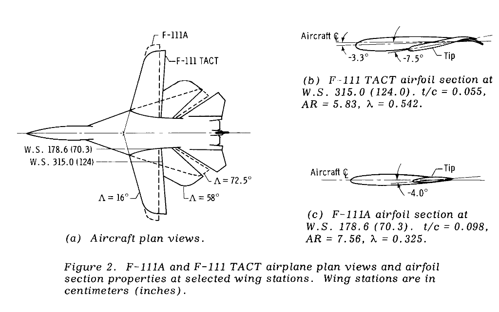
The image below shows the difference between the F-111TACT and F-111A. The airframes are the same, but the wings are drastically different. The TACT wing is shorter and wider that the A wing and has a curved tailing edge. The modified wing was designed to reduce drag (and thus increase efficiency) and reduce the “sonic boom” effects of crossing the sound barrier. The TACT wing was a precursor to the wings found on modern supersonic aircraft.
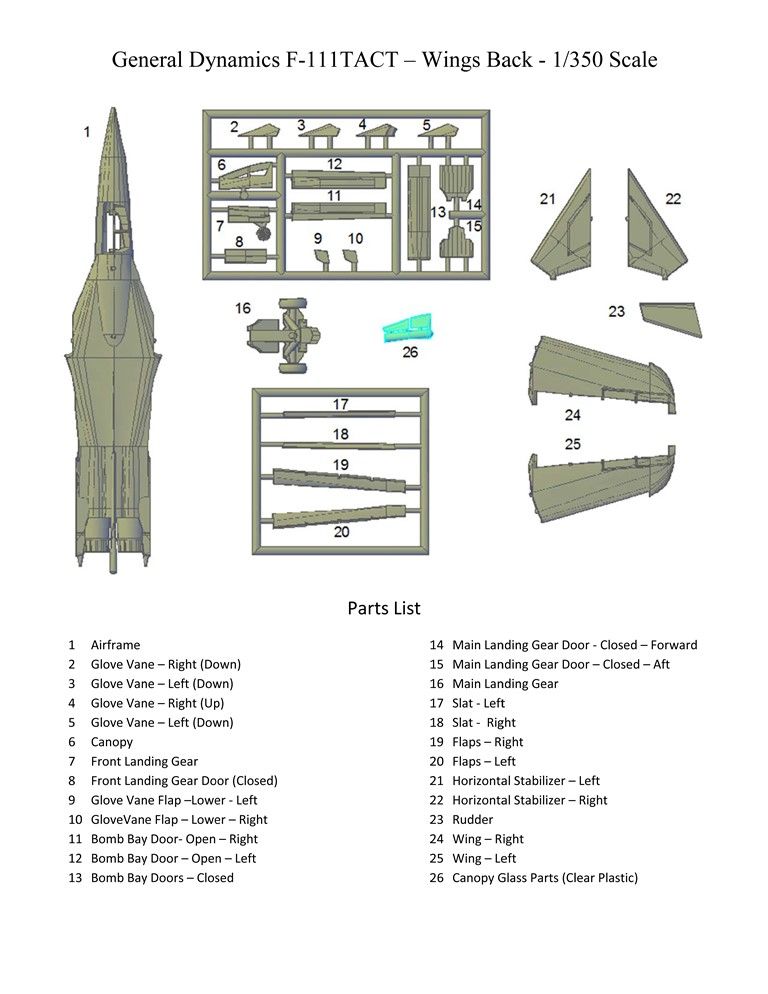
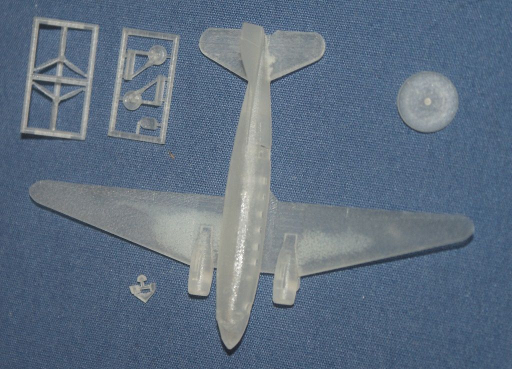
Although I am making these models for myself, Click2Detail (C2D) is now selling them on line, so I tried to design them to give modelers multiple options on how to display them. Tabs are included to assure proper positioning of the wings and “Wings Forward” and “Wings Back” versions of both models are available. The images below show the parts diagrams for the “Wings Back” F-111 models. The “Wings Forward” versions are essentially the same.

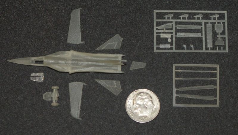
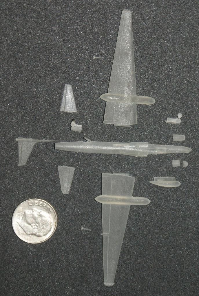
The picture below shows the parts for the F-111TACT. They are pretty darn small!
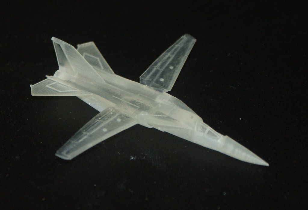
The next two pictures show the F-111A after I had assembled the wings and stabilizers in preparation for priming.

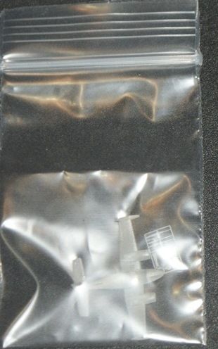
The parts diagram for the T-38 is shown below…
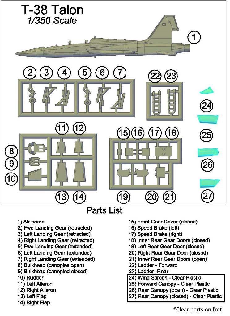
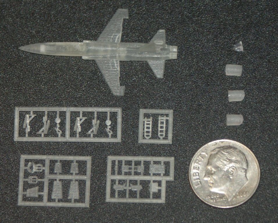
…And a picture of the parts, as I received them from C2D is shown below.
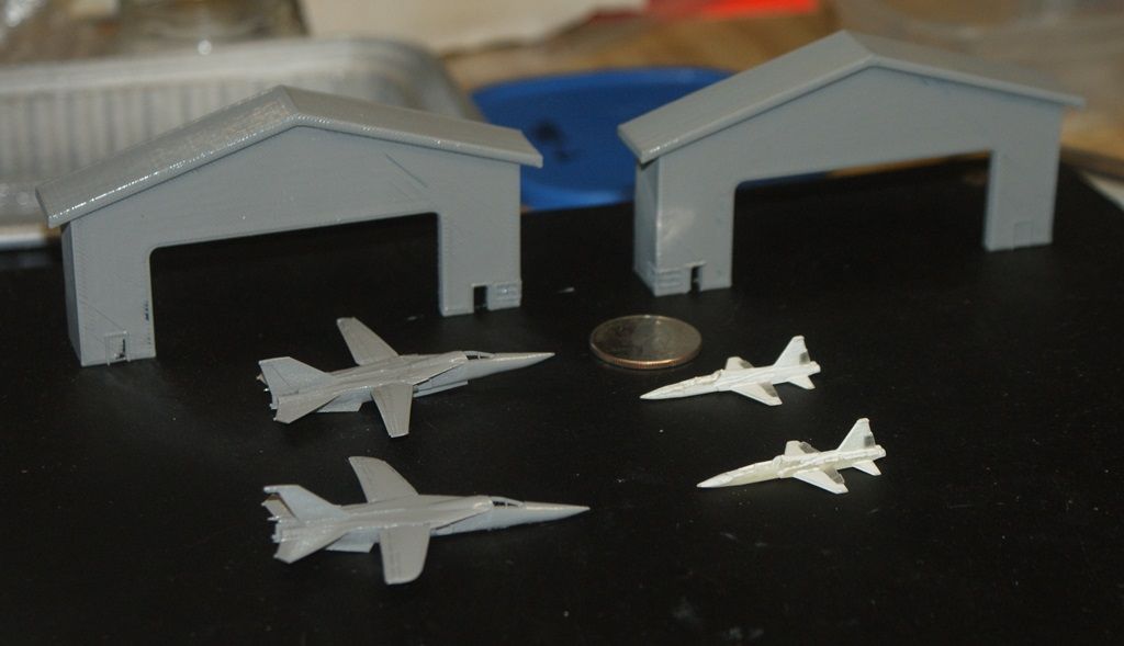
The next two pictures show the F-111’s with a coat of primer on them. Note the distinct difference in the wings on the two versions. The pictures also show the primed hangars and the assembled T-38’s before primer.

I have also received the U-2R from C2D.
I am thrilled, because even the detailed antennas “porcupine quills” printed out nicely.

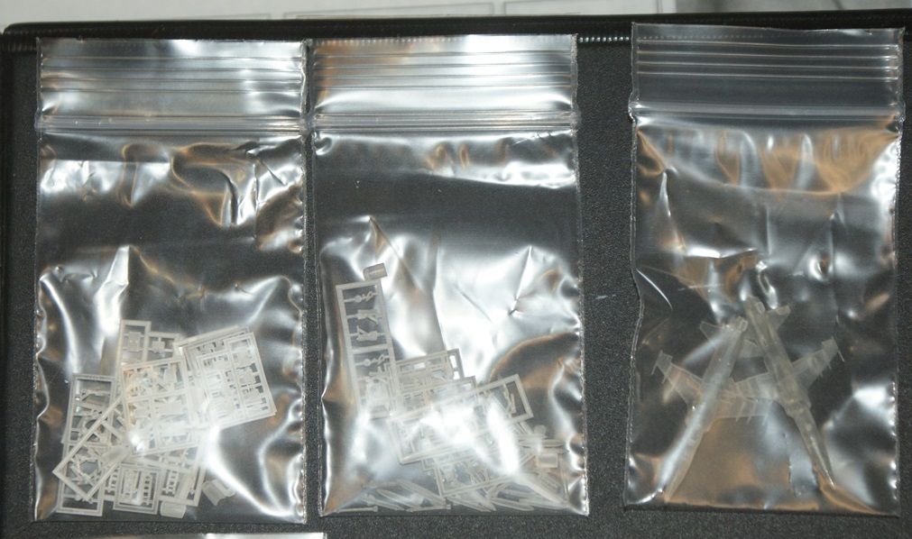
I have also received some models from Admiralty Model Works (AMW) who I am doing some design work in exchange for printing. The models from AMW, include the AC-47 (minus a prop that I received later)…
…The U-3A (still in the bags I received them in)…
…The two El Caminos (still in the bags I received them in)…

…And the two F-5’s (still in the bags I received them in).
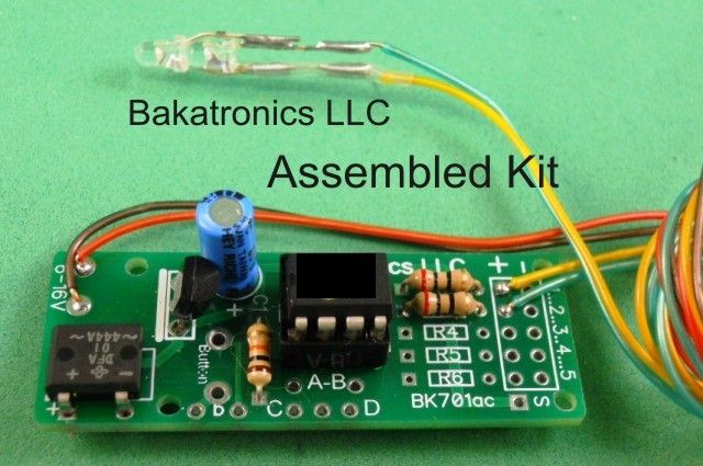
So, that’s where things stand on the project, with one exception. Earlier I showed a modified top for the tower that I had printed. This modified top was required because I decided to add a beacon light to the tower. I found a company (Bakatronics LLC) on-line that makes a “Simulated Airport Beacon Kit”. (http://www.bakatronics.com/shop/item.aspx?itemid=578)
The kit simulates rotation of White and Green Search Lights. Quoting from their web site, “When power is applied the micro controller starts a sequence that slowly increases the brightness of a Super Bright 3mm White LED. The slow increase simulates the light beam rotating toward the viewer. The micro processor then flashes the White LED to simulate the light being directly in your line of site, then slowly decrease the brightness to simulate the light beam going away from the viewer. When the White LED is completely off, the same sequence takes place with the Green LED. The white LED is clear in the off state, so by positioning the Green LED directly under the White LED, the White and Green Lights seem to eminate from the same point.”
You can see a video of it at: https://www.youtube.com/watch?v=lTMh62EbJ-k&feature=youtu.be
The kit itself costs $19.99, but assembly and testing are available for $9.99, and I ordered 9-V battery clip and slide switch, so that with shipping, it cost me $35.65.
The assembled kit is shown below, and reportedly measures 3/4" wide x 2" long x about 1/2" high. My current plan is to make a box for it in AutoCAD and print it at OU. It will fit nicely along the run way and will look good painted with a red and white checkerboard pattern.
As you can see, I still have a long way to go to complete this diorama project. I’ll post updates, as they occur.
CHEERS!!!