1/350 Scale Gulfstream IV-SP by R&R Modelers

UPDATE 20

Hi Everybody!

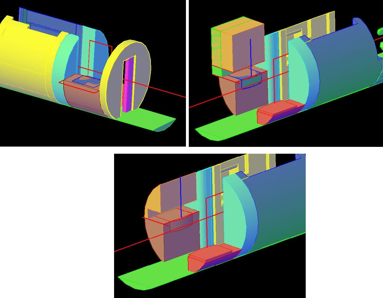
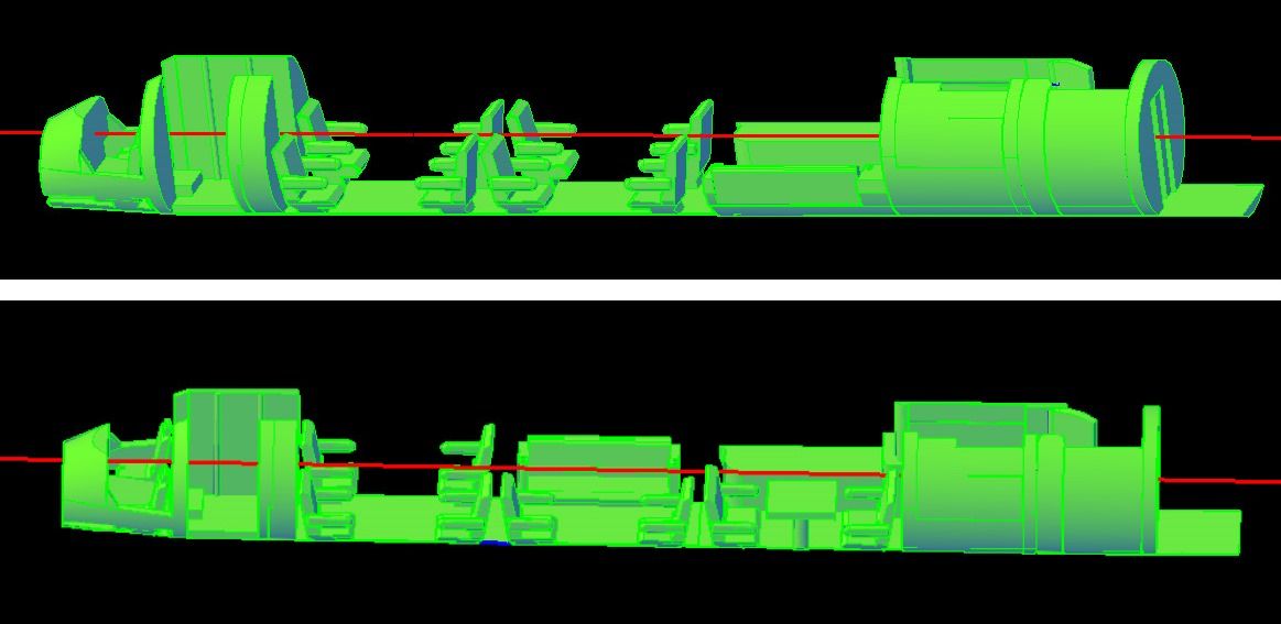
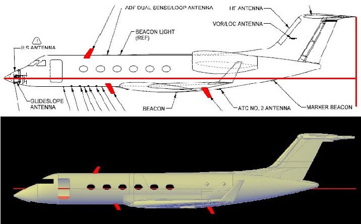
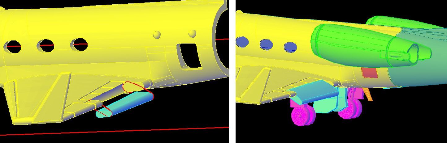
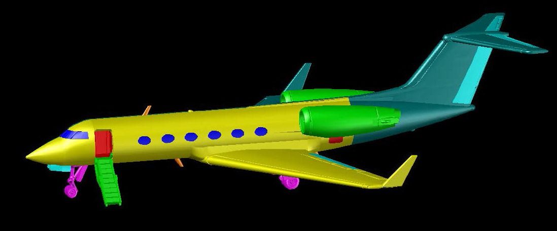
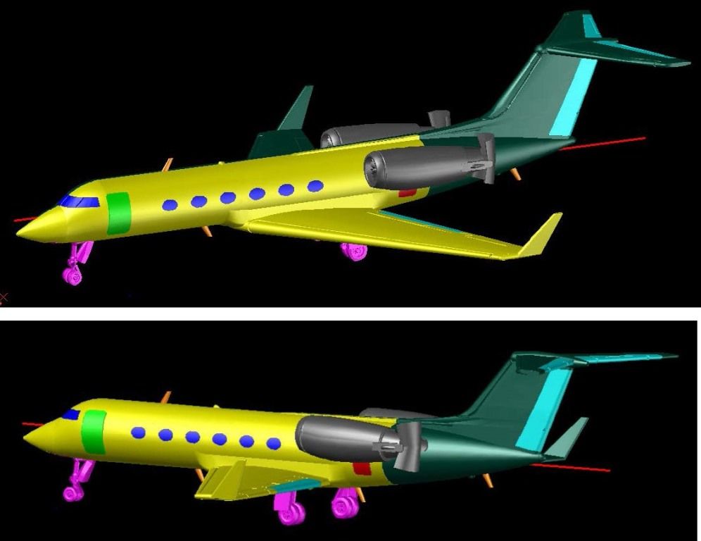
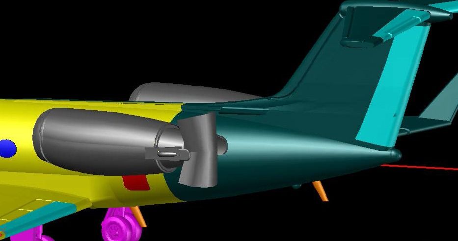
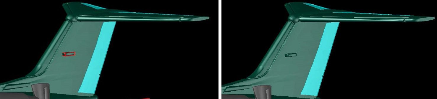
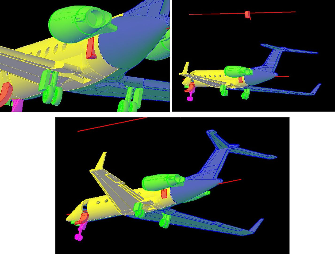
I woke up in the middle of the night, wide awake, so I got up and played on the GIV. Working on the interior, it occurred to me that the baggage room in the back had to have an outside access door. Sure enough, a look at the plans and poring through pix revealed that there is indeed a door below the left engine. The images below show the process which, by now, you probably know by heart. Trace, copy, extrude, copy, union, subtract, move.

In the few pictures of the GIV I have, showing the access door open, the door itself cannot be seen. Ron tells me it is on a track and opens in and up. At this point I am not going to do anything about that. If the modeler wants the door open, they can simply leave the door off, or attach it on the inside, as they see fit.

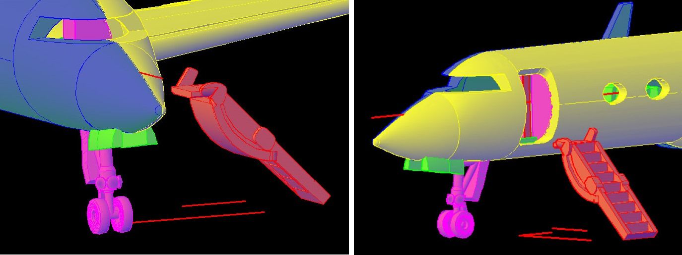
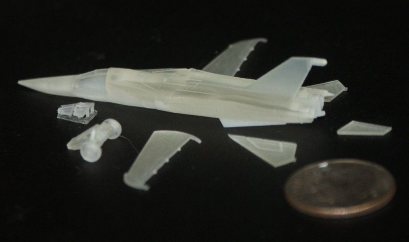
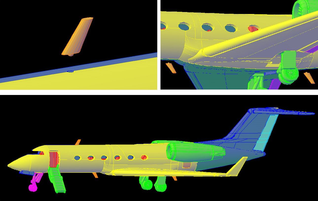
Instead, I decided to do the open cabin door and access ladder. Fortunately, I had several pictures to go on, including those shown below.

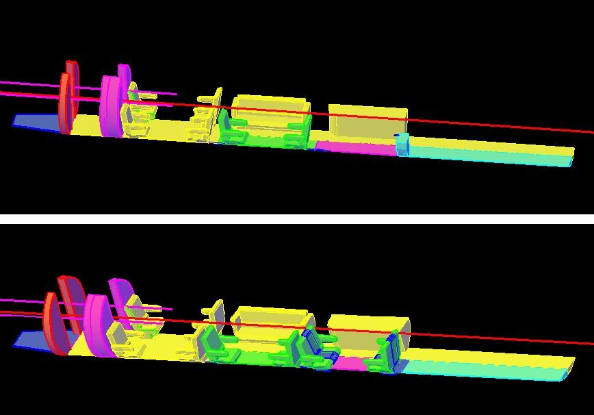
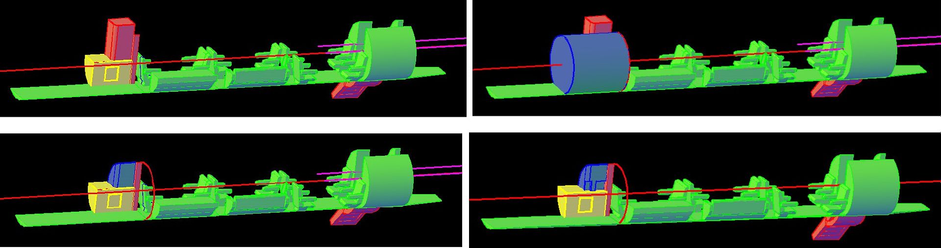
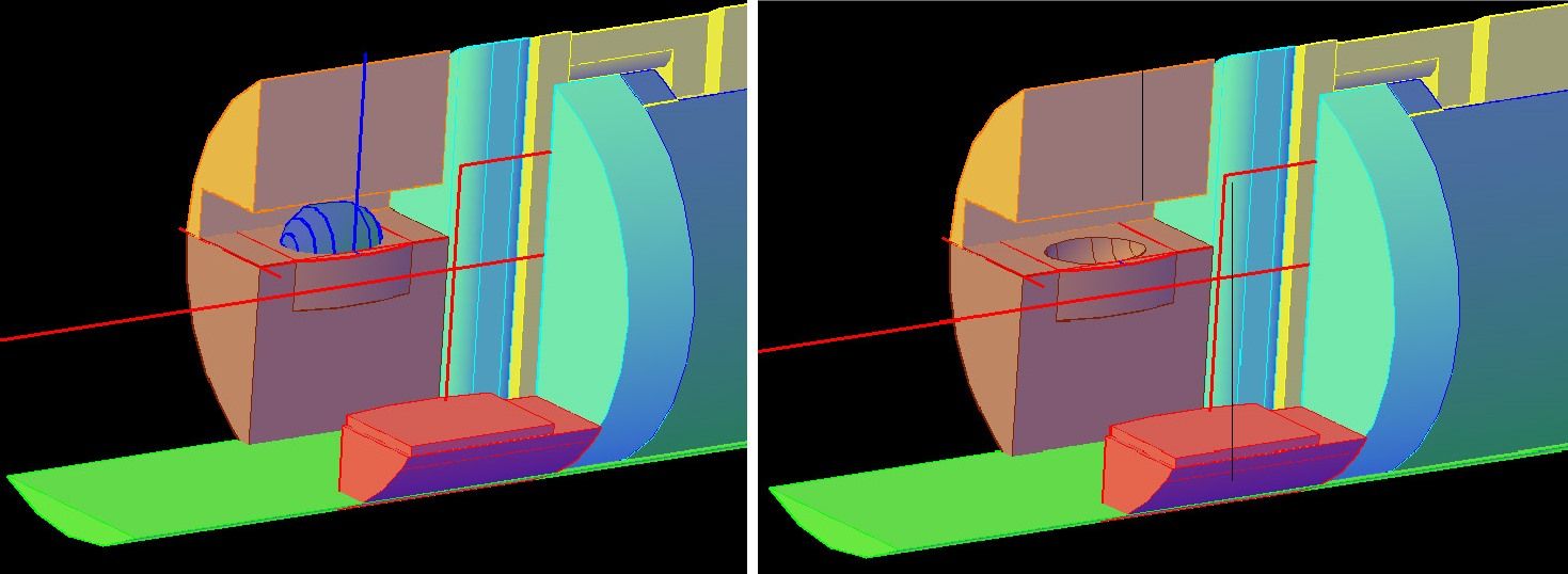
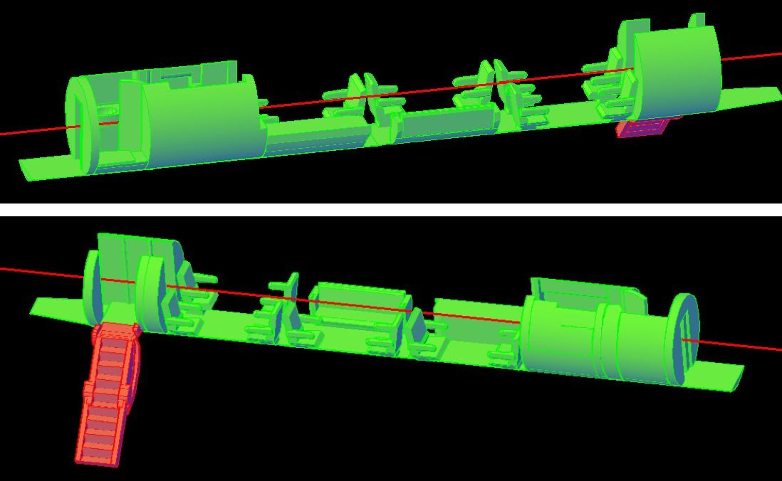
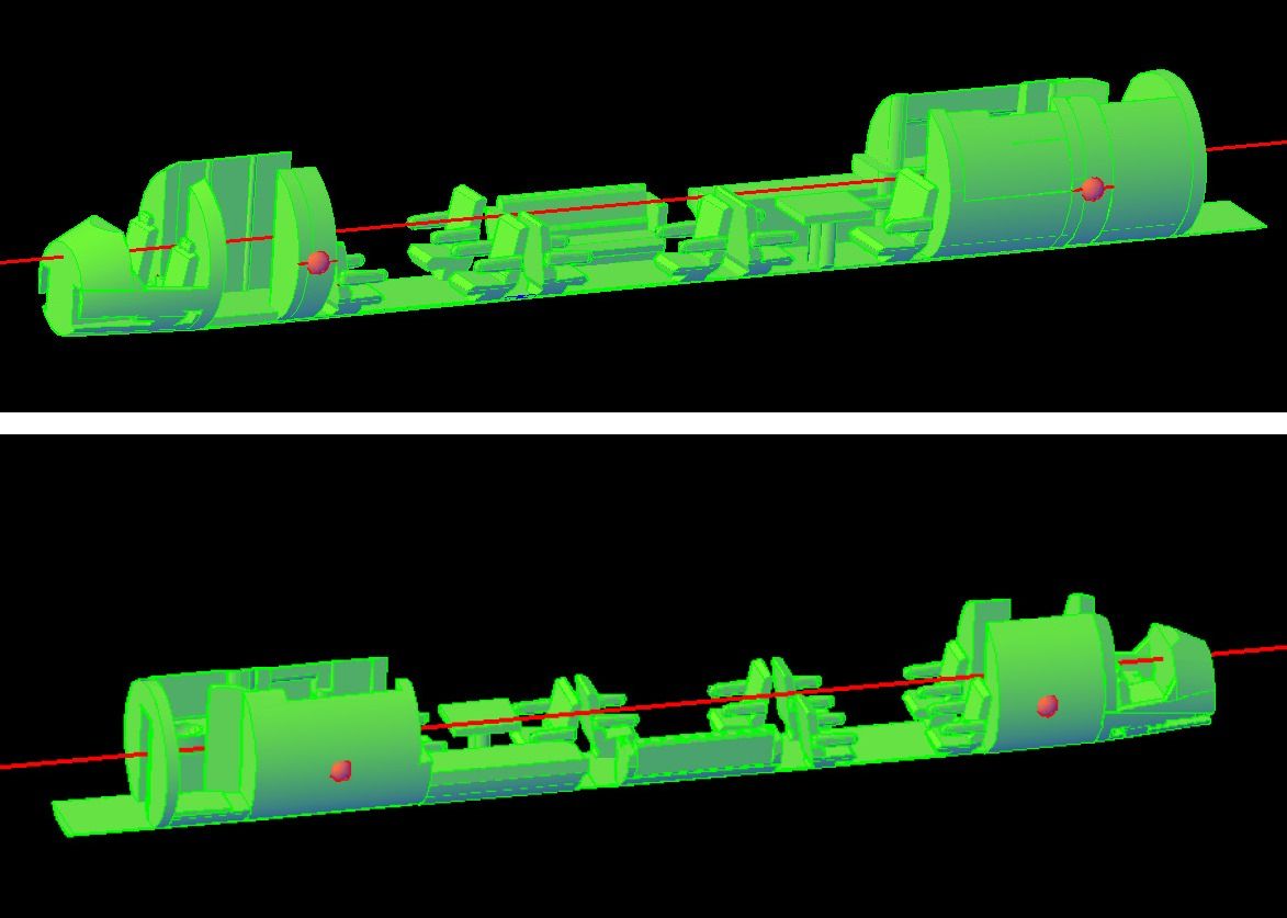
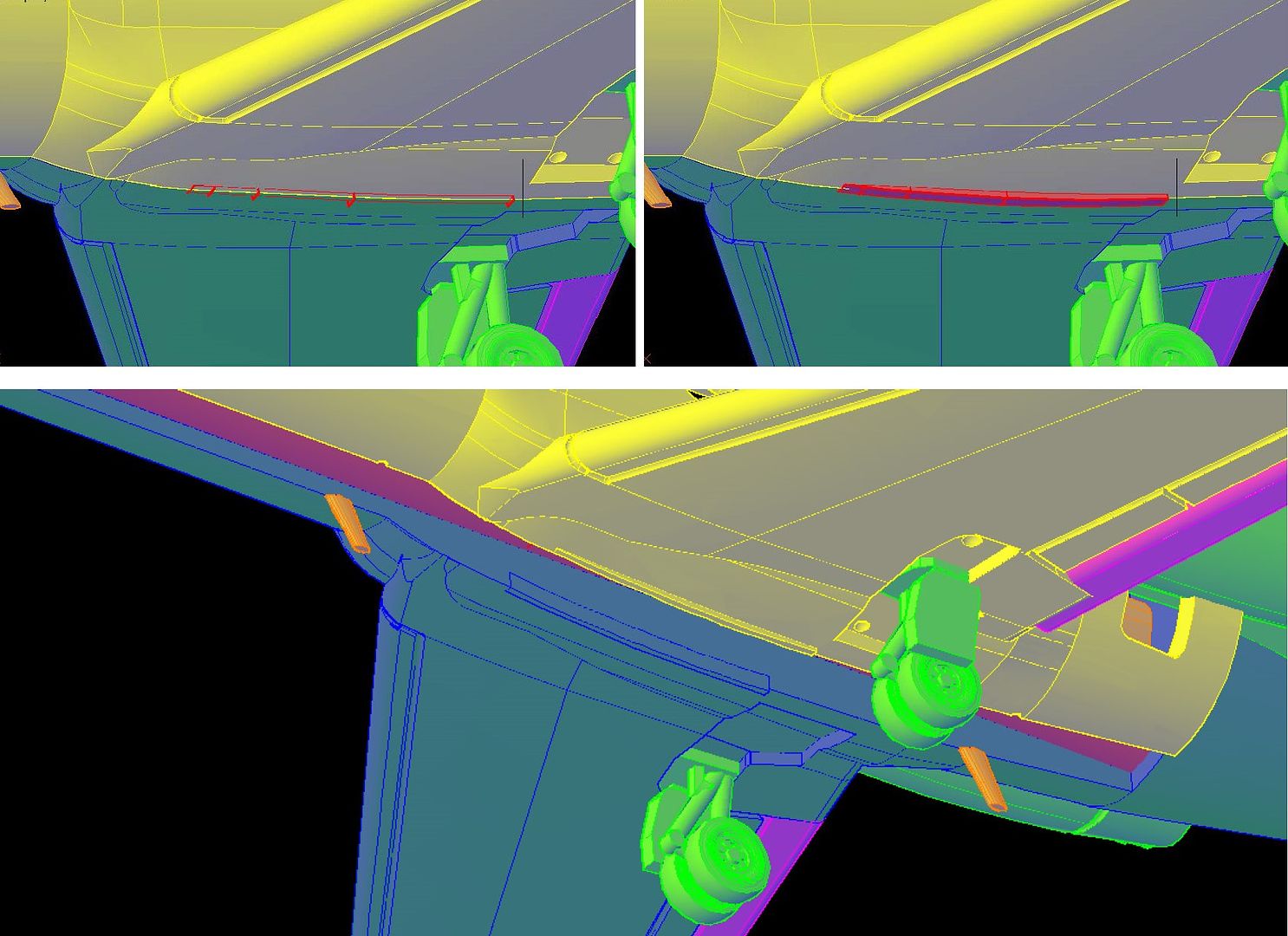
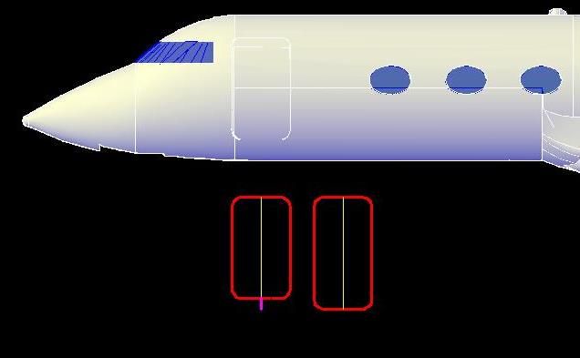
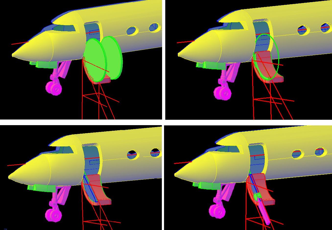
It was a lot of fun and quite a challenge trying to figure out how to do it. The first thing I had to do was give myself better reference in relation to the ground, so I extended lines straight down from the door edge as may be seen in the first image below. I then drew lines, from the bottom of the wheels perpendicular to these lines (not shown), and connected the intersections with a line. I then drew lines from these end points, horizontal out from the centerline of the aircraft. These last two steps created the “C” shape shown in the images, and weren’t necessary, but they helped me visualize the area better. The next thing I did was extend lines from the door edge down at a 45 degree angle, which was a WAG based on the few pictures I have. It turned out to be a pretty good guess. The green extruded circles, seen in the first image were subtracted from the door to create a notch in it, as shown in the second image. I then made the upper support arm (or whatever it’s called), as seen in the third image, followed by the lower arm and hinge{?) as seen in the fourth image.

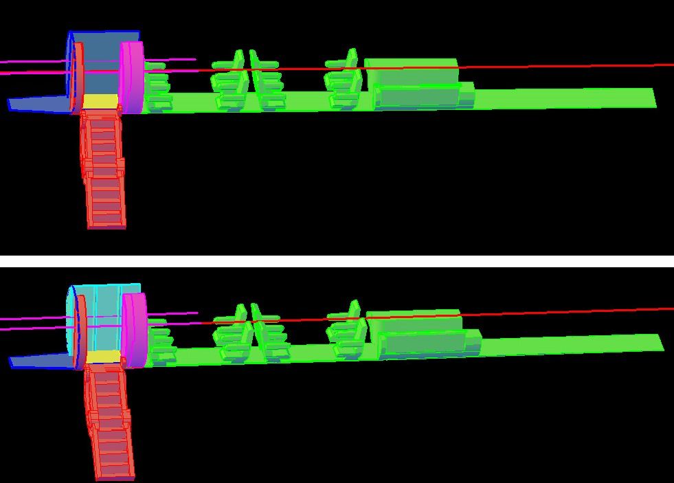
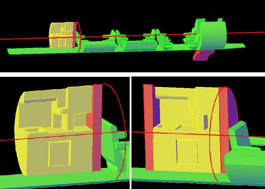
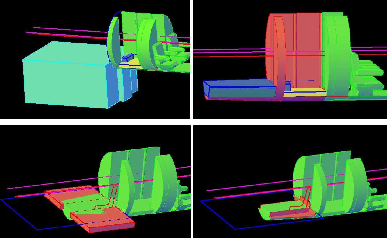
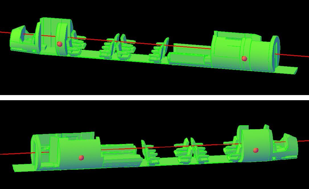
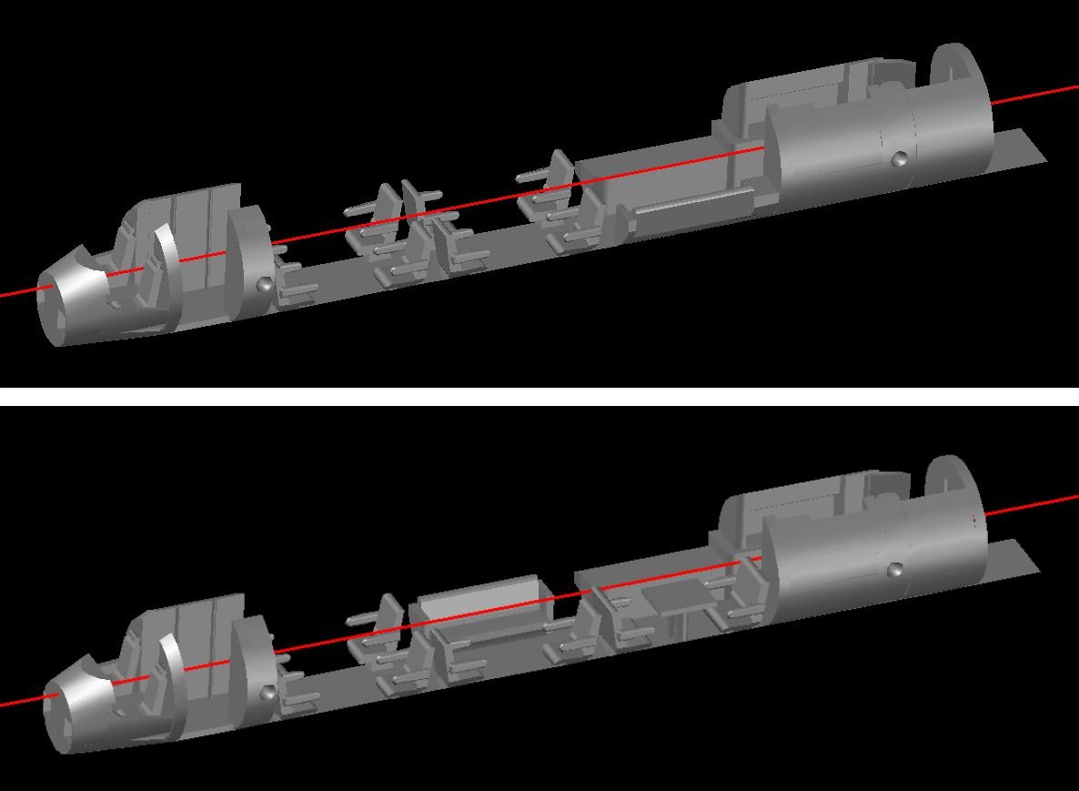
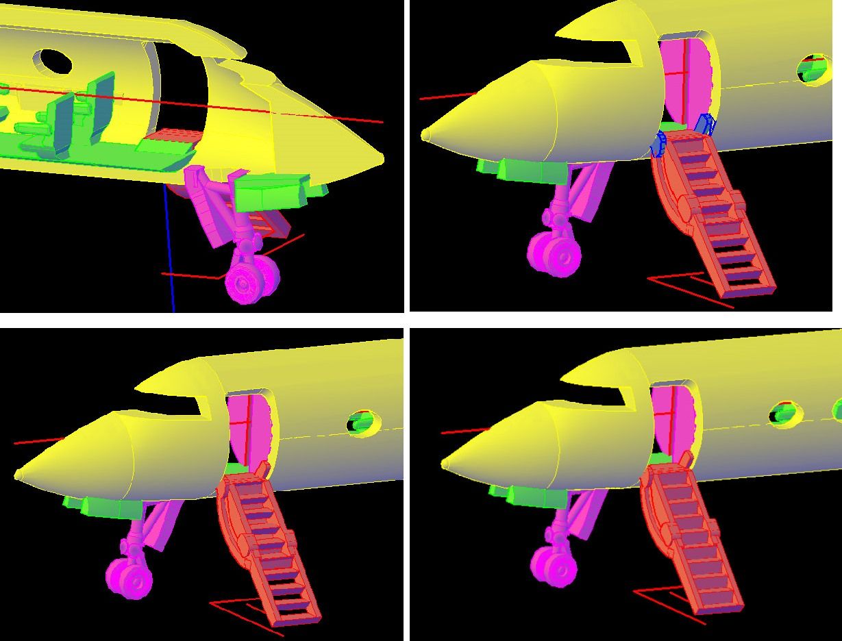
At this point, I mirrored the arms and hinge to the other side of the door (in this case I could have copied them instead) as seen in the first of the next group of images. I then created the lowest ladder rung, by extruding a closed polyline between the arms, as seen in the second image. The Array Command was used to create 10 equally spaced steps as seen I pictures (third image) and everything was joined together with the Union Command (fourth image.

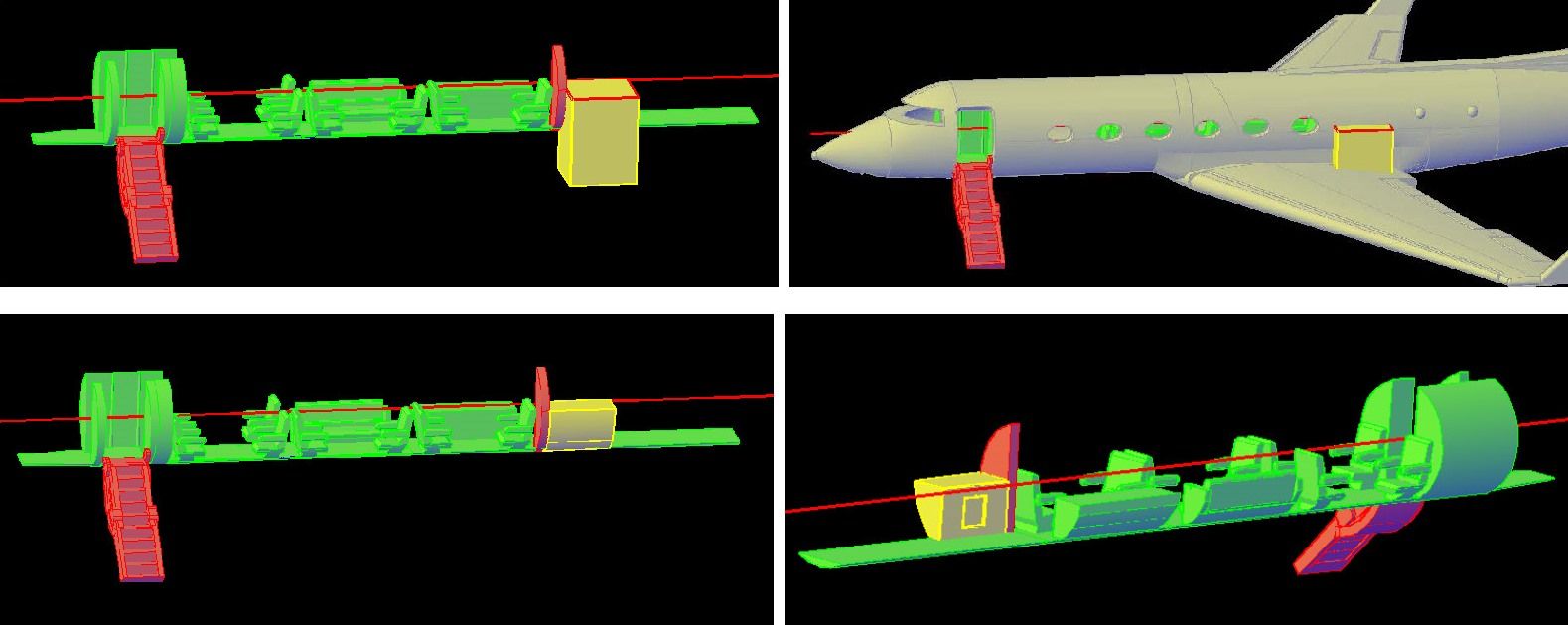
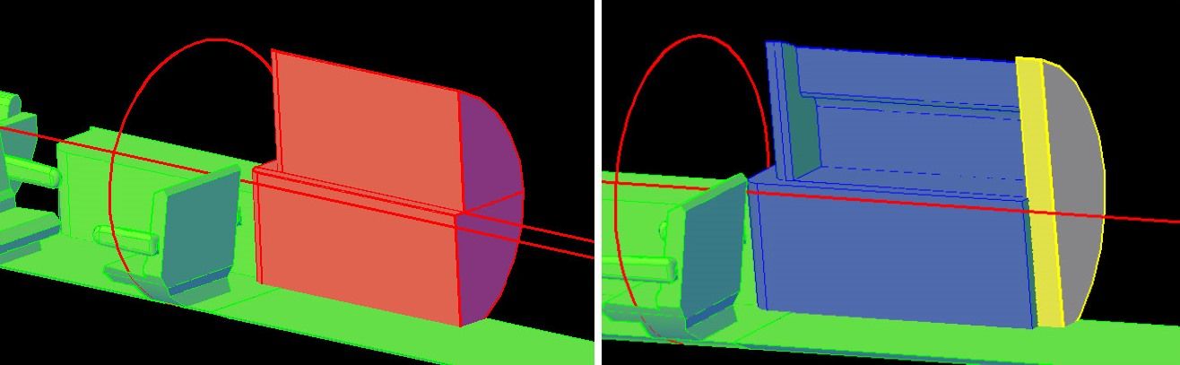
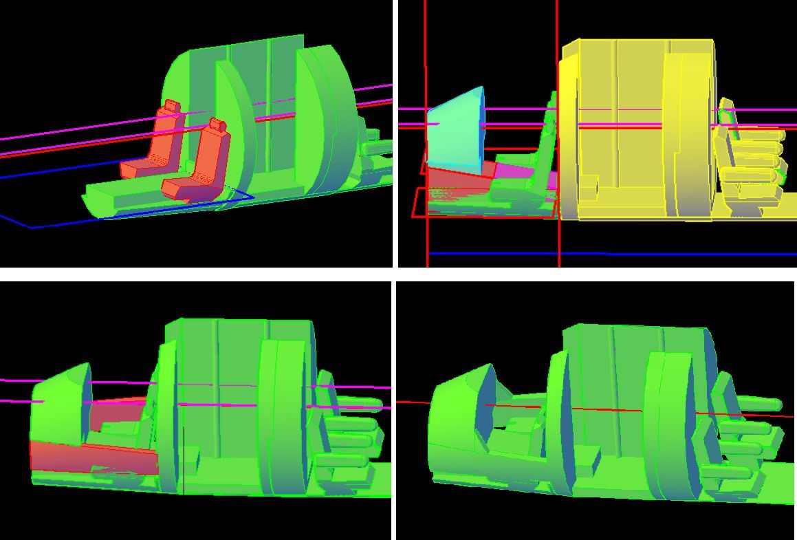
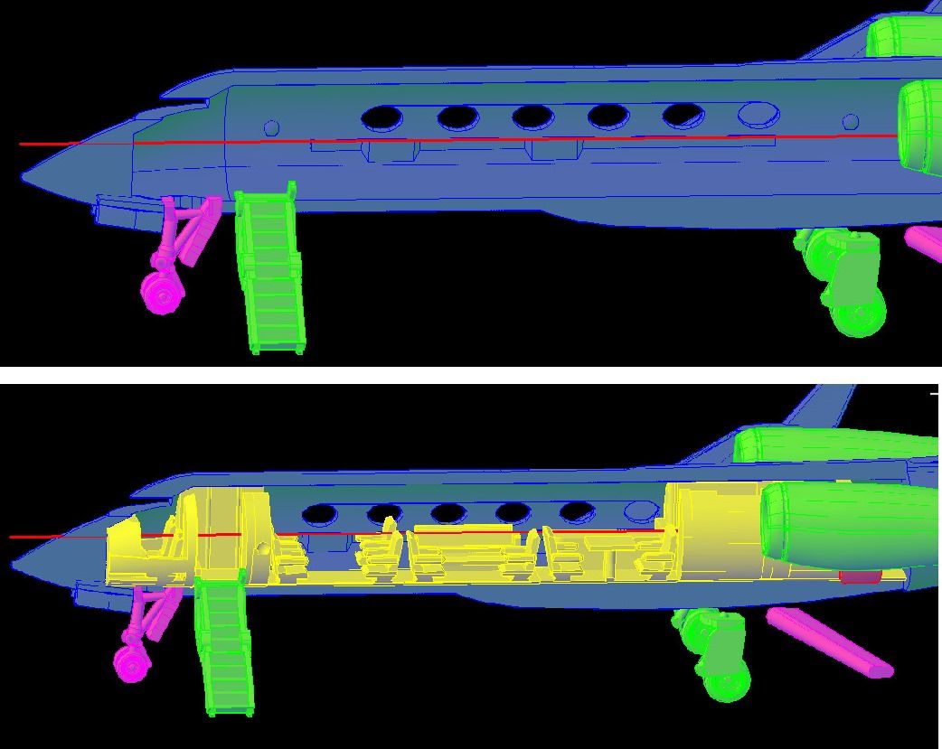
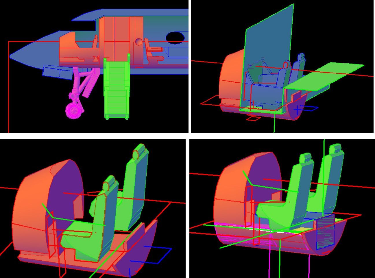
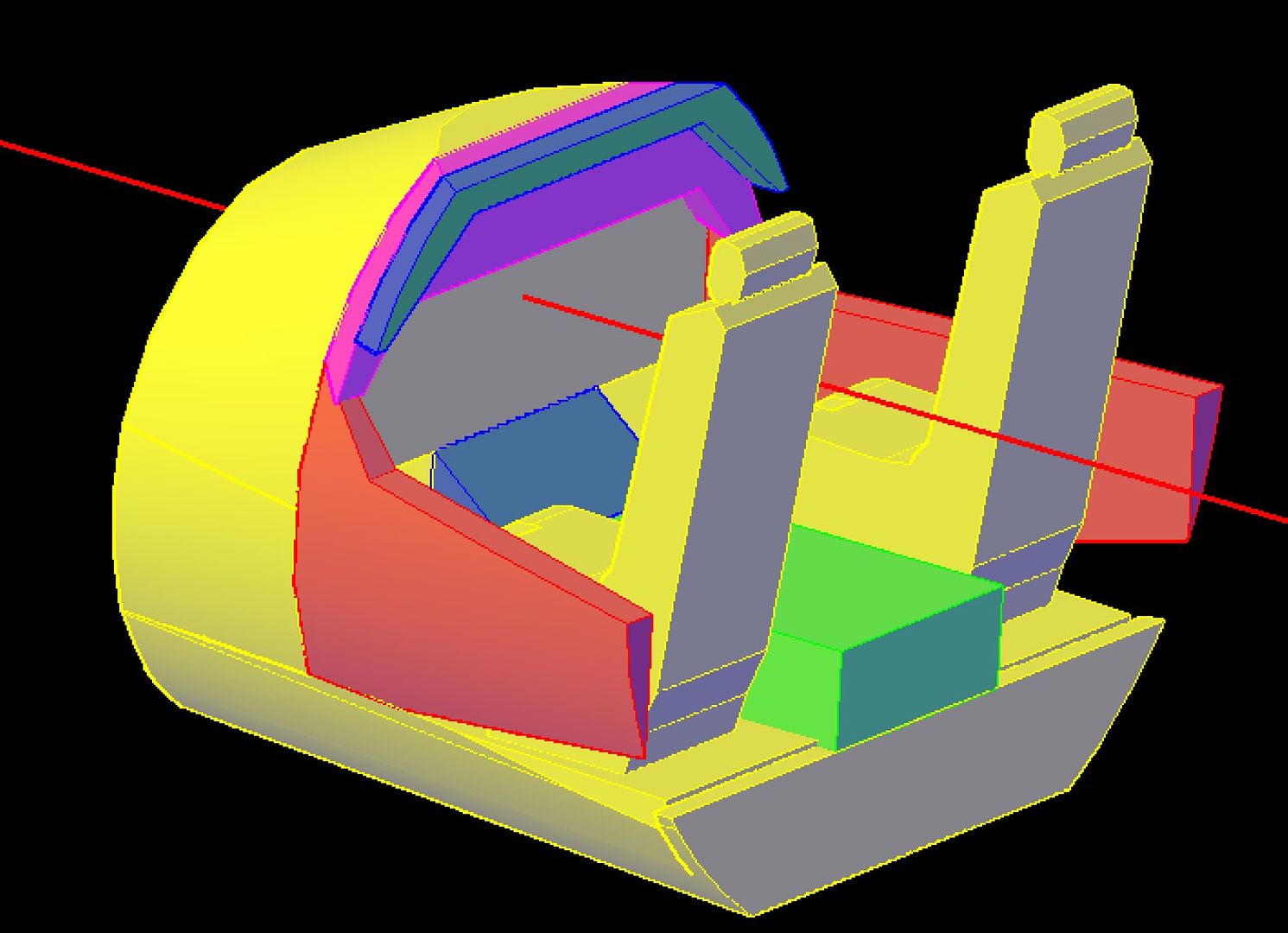
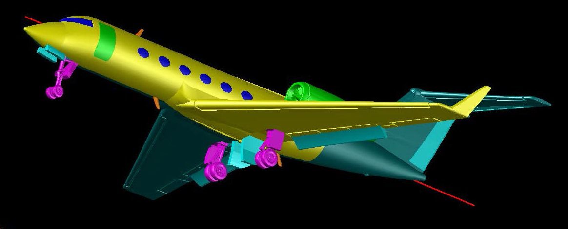
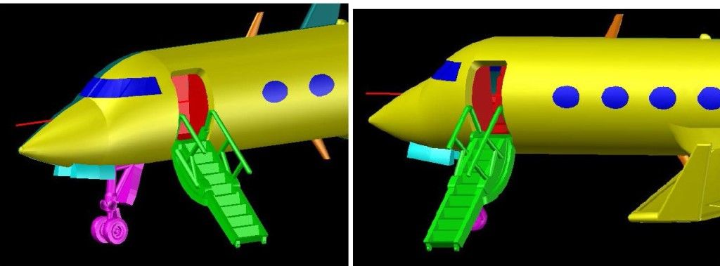
With the ladder created, I next had to figure out how best to attach it to the model. In the first image below you can see that the top of the ladder is slightly above the level of the cabin floor. This was done intentionally so that the open door/ladder assembly could be secured to the model. To match this surface, I created a ramp on the interior part to match the face of the top of the ladder. Next, I added the hinge and housing at the base of the door. Note that the bulkheads (magenta) have also been temporarily added to the interior. In the third image, I have joined the parts together, and in the fourth image I have added the front risers to the steps, noticing that the way I had them was wrong.

More on the door/ladder in the next update.

CHEERS!!!

UPDATE 21

Hi All!

Here are a couple of more images of the open door/access ladder, showing how it will mate with the aircraft.

Ron sent me pictures of the interior of his plane today (see below)and looking at them I noticed that the interior was not the Executive Aft Galley 12/5 as Ron sent me. It’s the Universal Aft Galley 14/6. The mistake is understandable due to the way the site is laid out. In any event, since I want to make his plane, I decided to modify the 12/5 to make the 14/6, before continuing on the ladder.

The first thing I did was copy the entire interior. This way I can include two interior options in the final model. After copying it, I sliced it down the middle, as seen in the top image below, and then segmented the pieces to isolate the bits that needed to be changed, as seen in the lower image.

After this, I sliced off the second group of chairs on the starboard side (blue), deleted them, and then sliced off the couch as seen in the top image below. Next, I mirrored the couch to the other side, deleting the old one, and moved it forward, as shown in the lower image below.

At this point, I joined the forward group of seats and the entire starboard side, as seen in the top image below. Next, I sliced off the aft group of seats on the port side (green), and moved them forward to where the couch was. I then sliced the seats in half and made them wider, as seen in the lower image.

The final step in modifying the Executive Aft Galley 12/5 to the Universal Aft Galley 14/6 was to join the parts together, as shown in the image below.

Now I have to decide what to do next. Decisions! Decisions!

CHEERS!!!

UPDATE 22

Good Evening Fellow Modelers!

The interior it was. Using the pix Ron sent, I added what the plan sheet calls a radio rack. Whatever it is, I added it by slicing an extruded circle, as seen in blue in the top image below. I then added detailing, to outline the door, by joining a 0.008” diameter surface tube to it, as seen in the lower image.

The next group of images shows the steps I followed to make the port side of the galley. Using pictures and the top view, I approximated the dimensions and height of the counter, outlined it with a closed polyline and extruded it down (first image) so that it would extend past the airframe, as seen in the second image. I then used the Intersect Command to create the lower part of the counter (third image). I added a refrigerator by first cutting out a rectangular area, then adding a slightly smaller extruded rectangle within the cutout (fourth image). Note that I had also added the bulkhead between the last seat and the galley.

The next group of pictures shows the construction of the upper cabinets on the port side. In the first image I have extruded the outline of the cabinet, and in the second image I have extruded the fuselage interior circle through it. The third image shows it after using the intersect command and the fourth image shows it after I created recesses in the lower portion of it, above the counter, to approximate the pix.

I got on a roll at this point and spaced out getting screen shots along the way, but using methods you have seen already, I added a vertical back wall, a sink, and a light above the sink, as seen in the images below. I also added the aft bulkhead.

Using these same methods, I also made the starboard side of the galley, and added the aft bulkhead, as seen in the images below.

Now for the luv.

I am just AMAZED that everything here is in 1/350 scale! WOW!! Incredible detail. I will definitely need to purchase one of your kits to give it a try.

To be quite honest Devil Dawg, it amazes me too. As I have been making the models, I have been adding more and more detail without actually seeing any of the resulting models. This changed yesterday, as I received my F-111TACT wings back version from C2D. Pictures of the model kit, as I received it, are shown below. (Well, OK, I took it out of the packaging it came in and laid it out for the pix.)

As you can see, it is tiny. In CAD, the drawing could be any size, from life size to 1/1000… and it would look the same. I haven’t done enough small scale modeling yet to have a good feel for the size of things at the 1/350 and 1/144 scales I’m making my models in. Seeing the TACT for the first time was a thrilling eye opener. Even though it is tiny, all of the detailing, done using the same methods I have been detailing for the GIV, shows up nicely. The super-critical wing shape, which is what separates the TACT from other F-111s, is evident. The wings and stabilizers align perfectly with the airframe, and the matching pins and recesses work just as I had hoped they would. Seeing one of my part frets for the first time was really cool. C2D had recommended that I do this for small parts, so I started doing it but really didn’t know how it would work. It worked great.

When I placed the order, I also asked C2D to do a test print of the instrument panel for the 1/144 scale FJ-4B, to see if it was worth doing more detailing like I did on it, or if it would be a waste of time. Well, I long since decided it was worth it and completed the model, again, without knowing how it would look. As you can see below, the effort wasn’t a waste of time.

As I have said before, I don’t have a lot of modeling experience, and I must admit that I am somewhat intimidated by the thought of putting the model together at this point, and am not sure where to begin. Fortunately, I have time to think about it, because I am going to finish the GIV before I start it.

Greetings All!

This afternoon I continued with the interior, moving aft to the lavatory. I started by adding the bulkheads between the galley and the lav as shown in the first image below. I next extruded an outline of the stool, and the base on the starboard side as seen in the second image. The third image shows it after I copied the airframe to the reference frame and subtracted it from the extruded part. Note that I also added a partially closed door to the baggage room. In the fourth image, I have extruded the counter outline down past the floor and added the top rounded section seen in pictures Ron sent me.

The first of the three images below shows the counter after subtracting the airframe from it. The second image shows the extruded shapes used to make the mirror faced cabinets (orange) and backing (green) and the third image shows it after I joined the parts and subtracted the airframe from them. (Note: the aft bulkhead layer is turned off.)

To make the sink, I created a half ellipse closed polyline and revolved it to make a solid ellipsoid, which I subtracted from the counter.

At this point, I decided to make the door between the galley and lavatory partially open as shown in the images below. In the third image, I have turned the aft bulkhead layer back on.

With the galley and lavatory sections completed, I joined the parts together and copied them from the Universal Aft Galley 14/6 to the Executive Aft Galley 12/5, then joined the parts together. The images below show the 14/6.

CHEERS!!!

UPDATE 24

Hello Everybody!

This evening I started on the cockpit. In pictures Ron sent me, the cockpit floor is raised above the rest of the floor, at least in the middle, so I first extruded polylines to replicate it, as seen in the first image. This extrusion was then subtracted from the airframe, as shown in the second image. Even though I don’t have good pictures of it, the floor has to be lower, so I extruded rectangles and subtracted them to create the lowered floor, as shown in the third and fourth images. Note that I have also moved a chair tracing into position for the port side seat.

In the first image below, I have extruded the seat subtracted the airframe from it, added a head rest, and mirrored it to the other side. Next I added the center console and the instrument panel as shown in the second image. These items were all created by slicing up the center core that I created a while back to hollow out the airframe. Next, I added the side consoles (third image) and joined everything together (fourth image). I did these stepson the Universal Aft Galley 14/6 but at each stage, I copied the items to, or duplicated the steps on the Executive Aft Galley 12/5.

The top image below shows the completed Executive Aft Galley 12/5 interior, and the lower image shows the completed Universal Aft Galley 14/6. Note that I added a table to the aft seat group to the 14/6.

In the next session, I will look at pictures to finalize detailing of the aircraft exterior.

CHEERS!!!

You may not be able to see everything when the model is finished but you’ll know it’s all there and it will make quite the topic of conversation when people see these drawings and photos. Ron

UPDATE 25

All I know Ron is that it is fun to do, and should be fun to build too.

Before starting the exterior detailing, I decided to add location pins and recesses for proper positioning of the interior. I don’t really think that this was necessary, because I think the shapes would dictate how the parts go together, but to make sure that they aligned properly I went ahead and added them, as seen in the images below. The spheres are 0.03” diameter. I did it for both the 14/6…

…And the 12/5

Next, I drew 0.028” diameter spheres at the centers of the subtracted spheres, and joined them to the airframe. The top image below shows the “pins” on the starboard side. The second image shows it with the 14/6 in place. Note the forward recess on the port side of the interior piece.

CHEERS!!!

UPDATE 26

Hi All!

When I was adding the connection points to the interior, I noticed that the cockpit seats were too low, as you can see in the first image below. Oops! So, I sliced it up, first slicing it at the forward edge of the bulkhead, then along the extruded polyline shown in the second image. I then moved the seat portion, along with their polylines up so that the headrests were just above the dash (third image). When I did this, the bases of the seats matched the level of the platform in the entryway, as seen in the fourth image. Note that after I had the seat parts positioned correctly, I deleted them and used the old polylines to redraw them.

With the seats raised, I could make the seats slightly thinner and make the side consoles part of the airframe parts as seen in the images below.

The image below shows it with the airframe parts turned on. You can see that the interior parts visible, if barely.

The top image below shows the Executive Aft Galley 12/5 interior, and the lower image shows the Universal Aft Galley 14/6.

Was it worth the time it took to do it? If it wasn’t so much fun to do, I would say probably not. But it is fun to do, and it certainly won’t make the model worse, I don’t think.

CHEERS!!!

UPDATE 27 – 3/25/2014

Good Evening Everyone!

Using a plan sheet identifying the locations of the antennas, I added them to the model, as seen in the images below. I created one using lofted ellipses, then mirrored it and copied it twice.

I created tabs on them using spheres, and since all three of them are on the centerline of the airframe where it is split, I had to subtract a 0.002” larger sphere from both airframe halves to make the recess for them as seen below.

After adding the antennas, I still wasn’t happy with the cockpit, even more so when Ron pointed a couple of features out that I hadn’t really noticed before, so I redid it. I didn’t document the process, but the result is shown below.

The interior parts are now completed as shown below.

Ron also mentioned the skid pad on the underside, and sent a couple of pix showing it pretty good, so I tried to replicate it by lofting between four rectangles as shown in the first two images below. Because the skid pad is also on the centerline, I had to slice it in half and add half to one airframe part and the other half to the other part. The third image below shows it with the port side of the airframe moved out a tad so you can see how the pad was split.

Some time back, Ron had pointed out that when the flaps extend out and down in the fully down position. I decided to make another part for those who may want to show the plane coming in for a landing, with flaps down. To make them, I moved the port side flap out and down as shown in the first image below. I then drew arcs connecting circles drawn at the base and the moved aft ends (also in the first image) and lofted them, as shown in the second image.

This completes the model, which may be built in flight, as seen below. Note the hole drilled in the underside to accommodate a 1/16”rod.

The model may also be built flaps down…

…Or on the tarmac.

Things remaining to be done include, putting the small parts of frets, making decals and making a parts diagram.

CHEERS!!!

UPDATE 28

Hi All!

Well, I lied. I wasn’t finished. First I had intended to put railing on the access ladder and realized that I had forgotten to do that, so using pix Ron sent me, I made a rough simulation of them, as seen below.

Ron also pointed out that his GIV has 4 antennas, instead of the 3 shown in the plans, and sent me another picture showing the location. In the picture, the thrust reversers were deployed, the first time I had seen them in action. I think they look cool so I made another set of engines with them doing their jobs, as seen below.

In yet another sign of the fortunate collaboration between Ron and I, he pointed out that adding the ventral ram air scoops on each side of the vertical stabilizer’s spine would add a lot to the model. I hadn’t noticed it before and agreed, so I added them using the plans (one of them actually had the outline of the scoops on it) and a pic Ron sent.

Now, with the model completed, I laid the parts out and put the little ones on frets. It’s easy to forget how small everything is, so in the image below, I added a dime for scale. It is to scale.

Below is a Part List I made for the model.

Now for the decals…

UPDATE29 – 3/29/2014

Hi Everybody!

Before doing the decals, I decided to add the VOR/LOC antenna on the vertical stabilizer, as show below.

To make the decals, I used this side view of the aircraft.

I did the decals in Paper Space with the model in a view port so I could draw over it easier. I started with the fuselage markings which consist of 5 enclosed polylines, 2 blue, 2 white, and a tan. Note that the markings are above the winglet. Next I added the letters using Amarillo USAF font that I italicized. I then traced the letter outlines of the letters and numbers, modifying the 7 and G slightly in the process. The tracings were then copied twice (down at a 45 degree angle) The outlines were then diced, sliced and rejoined to form the tan shadow, seen below.

The image below shows the decal sheet in progress. I have mirrored the port side decals for the starboard side decals and marked where the door openings would be. I also made the gray outlines for the aft four windows and the door. Note that I made the background light blue and changed the color of the aircraft to white. After all, that’s what color it is in real life. I also trimmed the decal set over the model, so it would look better. The actual decals are not cut. Last, I copied the port side engine just below the airframe.

In the image below, I have completed the markings on the engine and winglet, mirrored them and copied them all up to the decal section of the sheet. Note that I then trimmed the engine decal on the aircraft side view so it wouldn’t cover the winglet.

At this point Ron sent me a picture showing the wing walk outlines, so I added them, as seen below. I also added what appeared in the picture Ron sent to be Red arrows, which may or may not be correct.

For those who may wish to cut the windows out of thinner plastic than the 3D printer can do, I added templates that may be used for this purpose. The first draft version of the sheet is shown below. It was designed to fit on an 11”x17” sheet of paper and needs to be reduced 25% for proper scaling.

Note that I said first draft. This is because I know it is going to need modification, because curved lines are longer than straight ones. Consider the door shown below. The outline of the door that I used to cut it out of the fuselage ison the left, and the outline of the gray door decal is on the right. Note the extra length, 0.02" to be exact. This is because the decal is on the circular surface of the door. The length of the decal is the arc length associated with the chord length of the airframe diameter.

The door was easy to do, the fuselage decals, which are curving on a surface that is curving in two directions, is another matter. I know that the decals need to be lengthened in both directions, but I have no idea how much. You can break it down into 4 sections, the nose (from the door forward), the body (where the sides are straight), the aft end, and the tail. The body and tail surfaces are essentially straight so no length adjustment is necessary, but the nose and aft end are a different story. The increased length on the nose, I think I accounted for by adding some length up front. It may or not be enough.

The aft end starting at about the winglets in the side view, is essentially a cone, so it curves on 2 planes. If the markings were straight, it would be difficult but with them curving too…, Man, I can’t figure out how to do it. I know that it needs to be at least 0.02" longer in the vertical direction, but how much longer in the horizontal direction, I don’t know. And the really hard part is that the stripes don’t all need the same amount of stretching. This is definitely a thought provoker. Does anybody have any tips on how to approach this issue? Any and all comments would be appreciated.

In the meantime, I made some minor modifications to the Parts List and Diagram. The final version is shown below.

CHEERS!!!

UPDATE30

Hi Everybody!

Well, the engineer in me took a back seat to a WAG. I just made the decals slightly longer than they needed to be and split the long ones into two pieces at the location of the hatch (on the port side) as seen below.

The model and decals have been uploaded and are available at C2D.

https://click2detail.com/products/CY/Gulfstream-IV-SP

I’m getting one of them to go in the diorama I am doing with my 1/350 scale planes (and perhaps one or two 1/144 scale suspended in flight). I have a place for it, as seen below.

I have printed the base, which is different than my initial design…

…And have cut out the grass areas and attached it to my base board. The 1/144 scale aircraft would be suspended from the overhanging shelf, if I decide to add them.

Ron has also ordered 3 and will no doubt work his magic on them at some point in the future.

CHEERS!!!

UPDATE 31

Greetings All!

It’s been over 2 months since my last post, but C2D had problems with their printer, and weren’t processing any orders. They have got it fixed now, and I received the G-IV on Friday. I’m really happy with the way it turned out.

I also received my two T-38’s…

…And my F-111TACT. These, like the G-IV, are 1/350 scale models I made to include in my diorama.

The next step is to wash them with isopropyl alcohol.

Ole! Ole! Ole! Ole!

I wondered how long it would take before somebody showed us just what goes into designing and fabricating a kit before we get the joy of assembling it. This thread should be mandatory reading for everyone on the forum, I know I sure enjoyed it. Kudos on a job well done!

Pat.

UPDATE 32

I’m glad you enjoyed reading this WIP Pat, and I appreciate the response, but if it was mandatory reading, nobody would enjoy it. [:D]

I’m not sure that the process I show is anything close to what the big model makers use, although I think that the process would be similar. Of course this would be just the first step for them, because they would use the 3-D printed parts to make molds, which they would then use to cast the parts in resin. I know very little about the molding/casting process, but it seems like it would be time consuming and messy.

The main problem with 3-D printing at the moment, in my opinion, is cost, so if you are going to make and sell a lot of a particular model, it is cheaper to make them in resin. I don’t know what the magic number is to make it worth the effort, but I think 3-D printing is the only option for limited production.

The best part of 3-D printing though, is that it allows you to make whatever model you want, so that you aren’t limited to what is on the market, and you get to make 2 models, first the virtual model, then the real McKoy.

I sprayed the large parts of the G-IV with Future, and after they dried, I sprayed a coat of white Rust-Oleum Plastic Primer on them. I didn’t do a very good job of it, but I still need to sand it, so it should be OK.

I also did the T-38’s at the same time.

CHEERS!!!

Hopefully you won’t have to do too much sanding and the thicker base coat should mask most of the stepping if there is any. Your models are fantastic and the ones I purchased are well worth the price I think.

Ron

Man, they are small…but cool!!

UPDATE 33

Thanks Ron and Rob, I appreciate the kind comments!

It’s been a while, but I finally found time to play with the Gulfstream model some more. I just finished painting the interior, and in hindsight, I should have made the kitchenette cabinets and sink part of the fuselage sides. The way it is makes it really hard to paint. I didn’t even try painting the sink and mirror. I was lucky to get the brush in there to get any paint on it.

My colors aren’t the best, due to my limited color options. I used Testor’s enamel Light Tan for the carpet, and then attempted to mix it with white for the cabinets and table tops. It’s not the best, but the real color would be really hard to match. It seems to have a yellowish tint to it in places, but it isn’t a solid color.

I still don’t know how and the heck I’m going to do the windows, but I’ve got some time to think about it.

CHEERS!!!