Bob…fantastic report…I bet it looks magnificent for sure.
All that illumination…mmmm.
Rob
Bob…fantastic report…I bet it looks magnificent for sure.
All that illumination…mmmm.
Rob
Rob,
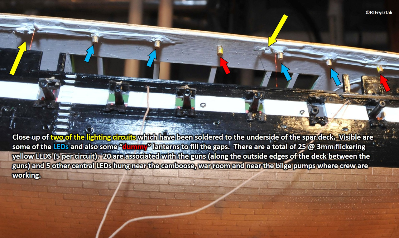
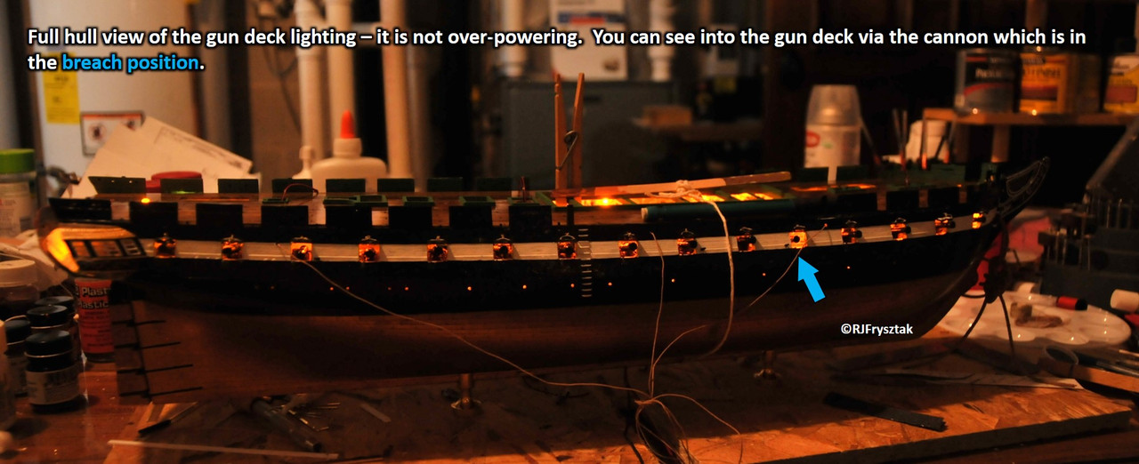
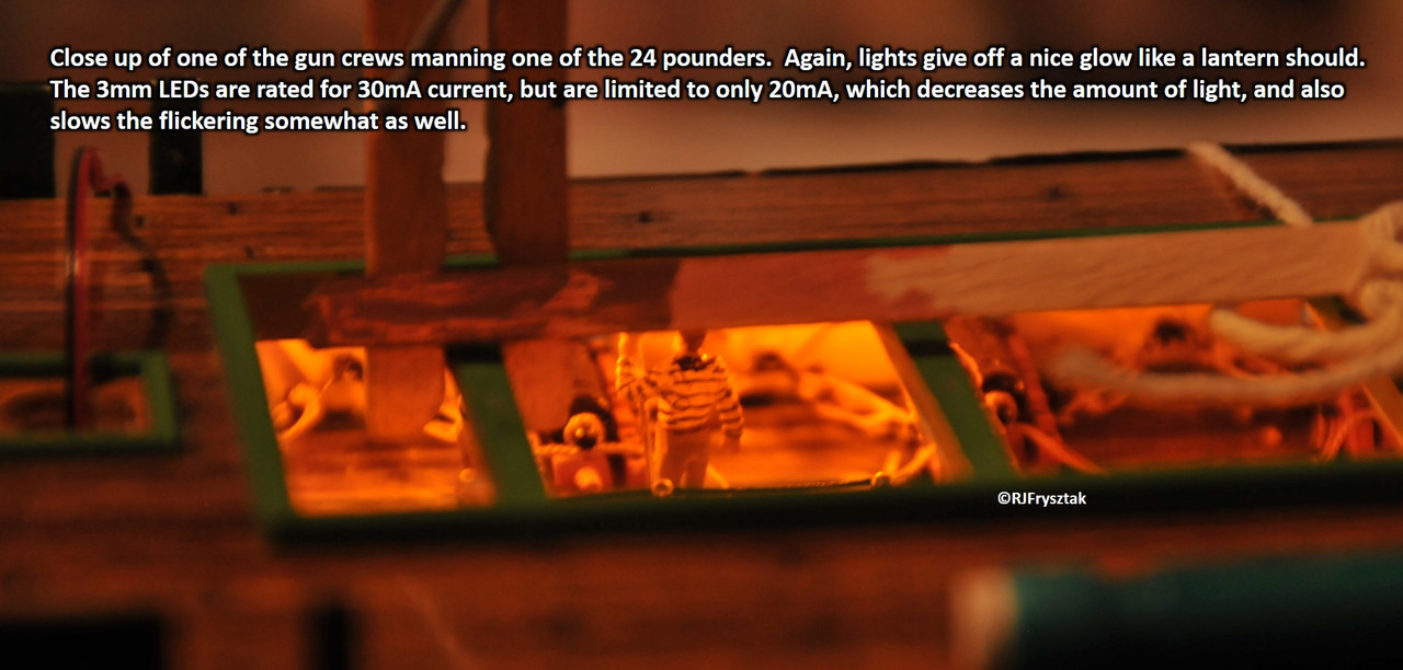
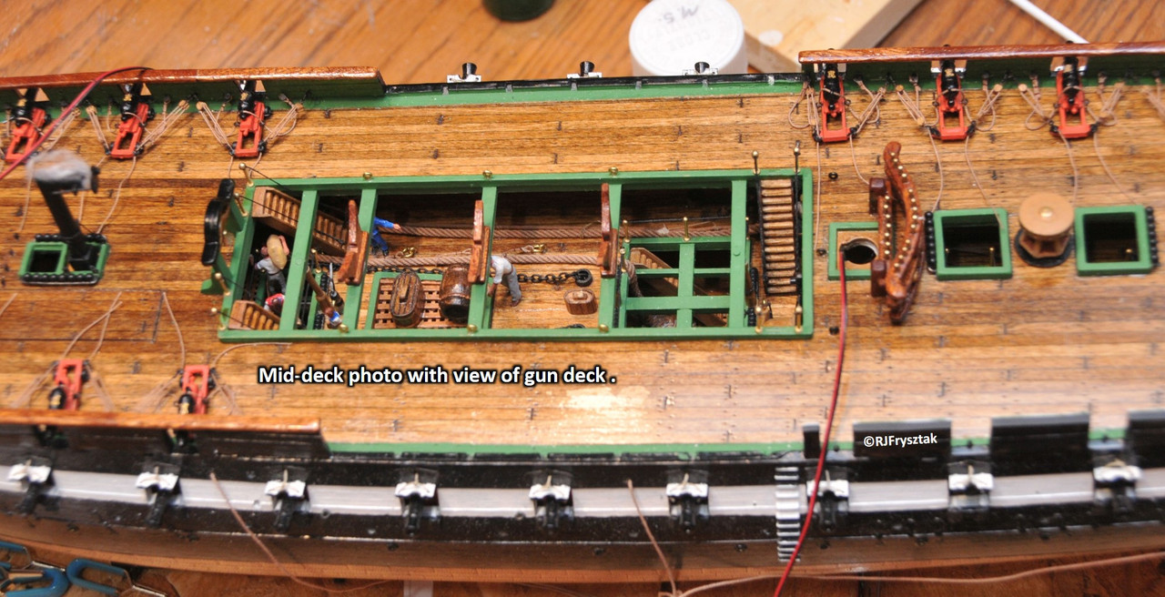
These are just the 3mm water clear LEDs rated for 30mA, and I am only pushing 20mA through them, so it is just a dim yellow glow from each. Mounted them between every other cannon. I also filed each LED flat and painted them to look like brass lanterns using brass enamel paint. This further limits the light. Nothing directly out of the end so it doesn’t create a “hot spot” on the deck. Also hit the clear lens with 400 grit sandpaper to soften the light a bit more. Big deck - almost 24 inches from bow to stern - so the number of LEDs is about right for even lighting of the entire deck - plus a glow coming up through the open hatches and lattice. My wife says it looks fabulous, so I guess it is okay. Pics a bit later (maybe a video).
Bob

Wonderful indeed.
The issue of providing enough light and keeping the light brightness to scale (flickering candles, that provide lots of shadows, NOT a well lit gymnazium) can be challenging I’m sure…not to mention the capturing of light leaks around cracks and joints and preventing light from creating that opaque bleed through the plastic hull/fittings.
You need a tight light box…controlled that is.
Great job for sure.
Rob
Ron,
Thanks for the compliment. I have some experience in this area from lighting my pinball mods.
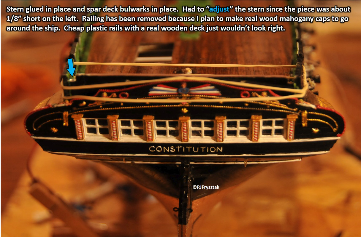
Since I beefed up the walls of the ship, I wasn’t overly concerned about light bleeding through there. Same can be said for the 3 layered deck I built. Hardest part was the stern. The one piece gallery doesn’t fit very tight, and even minor errors with the hull halves can be multiplied back there. I did a LOT of measuring before and after the hull was glued together, to get the deck widths correct so that everything would line up and be be “light tight.” I even added a very flexible extension (.010" styrene painted black) which flared out from the bottom of the gallery and extended into the hull an extra two inches. I also added miniature kickboards around the cabin floors so that nothing could leak through the gaps between the walls and decks. The only area left where light may leak through will be the masts, which I have rings for.
Looks great, Bob! The lighting is wonderful.
Bob, That is fantastic work and a beautiful Replica. Thank you for creating this thread.
And a Happy very-belated Birthday. I should have remembered. Mine is May 7 too.
Jim.
Nino & Steve,
Thanks for the kind words. Adding the lighting is just my way of making things as complicated as possible. Seriously, though, I really wanted this version of the ship to have all the bells and whistles that I couldn’t even have imagined 35 years ago. When I finally get her done, I may go back to some of my old sci fi kits that have been sitting in boxes for years for a change of pace. I still have more boats to build, but going to all wood on the next one. Got a great deal on the Niagara kit, and I have a Sovereign lying around as well. Getting lots of experience on making wooden part with the Connie: masts, spars, railings, fife-rails, etc. will all be wood (mostly because many of my plastic parts are warped or missing pieces).
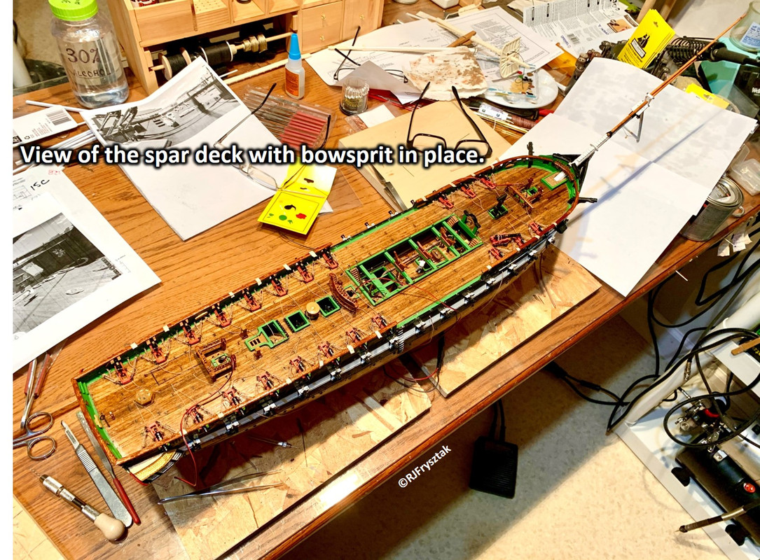
More pics when I get the spar deck completed.
Bob
Bob, not only is your work beautiful, but the electrical you do is unbelieveable.
Thanks Gene. Means a lot to me.
Bob [:)]
Working on the spar deck furniture, like fife rails and pinrails. Started with the fife rails.
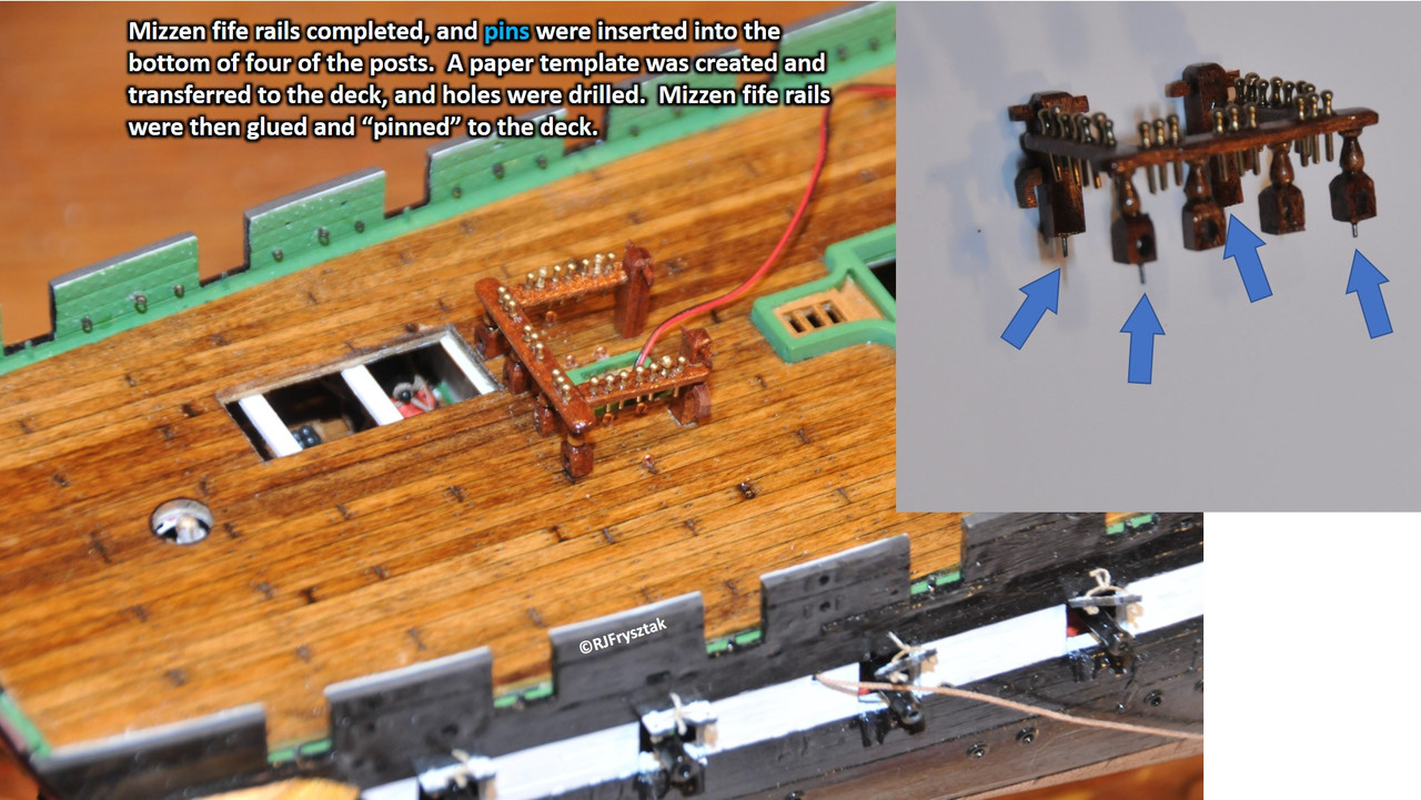
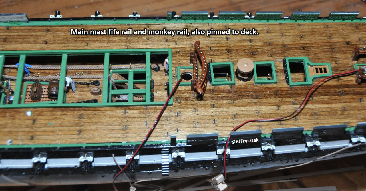
Bob
Just got back from a much deserved vacation (been 3 since we have gone away).
So I thought I would catch you up on progress.
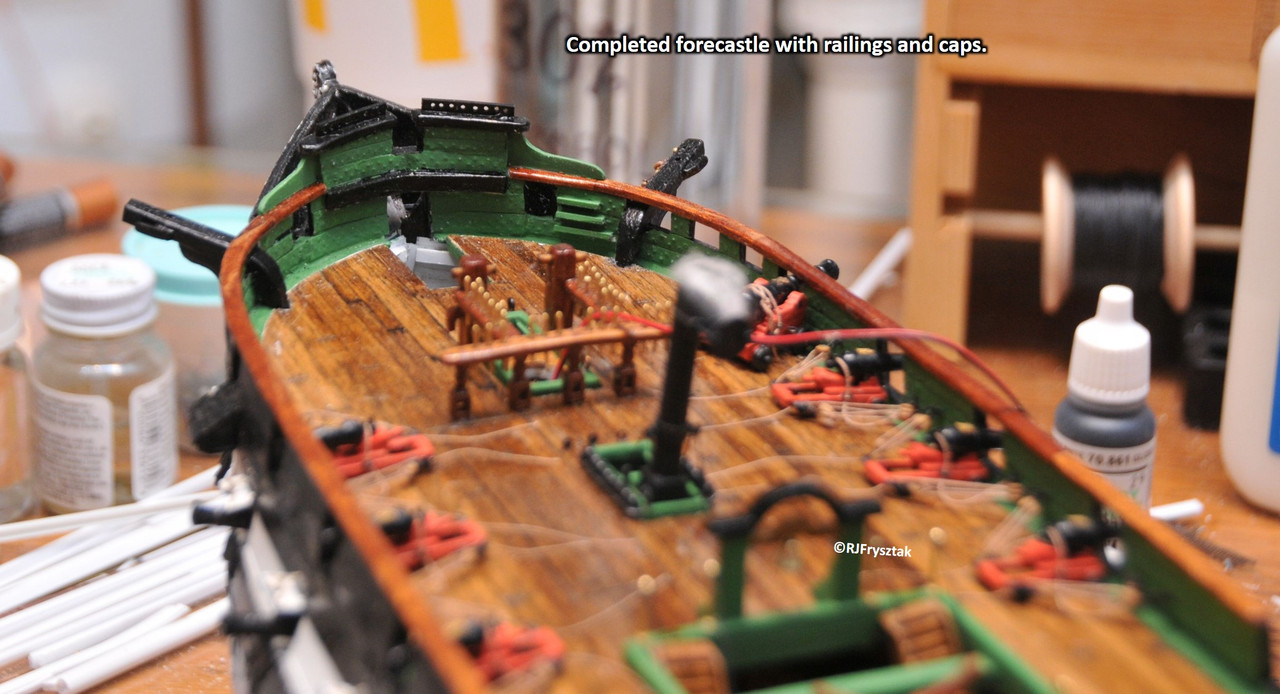
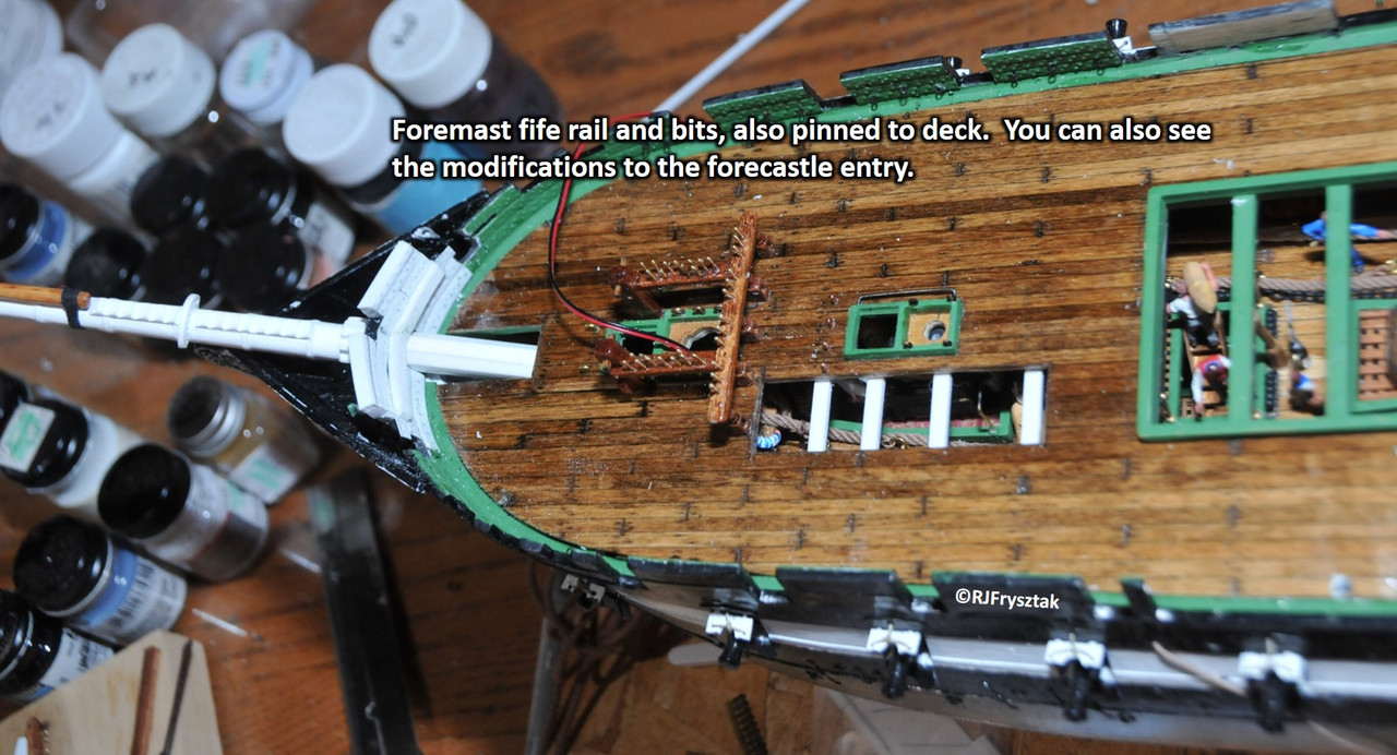
Finished mods to forecastle and added wooden rails and all the fore deck furniture.
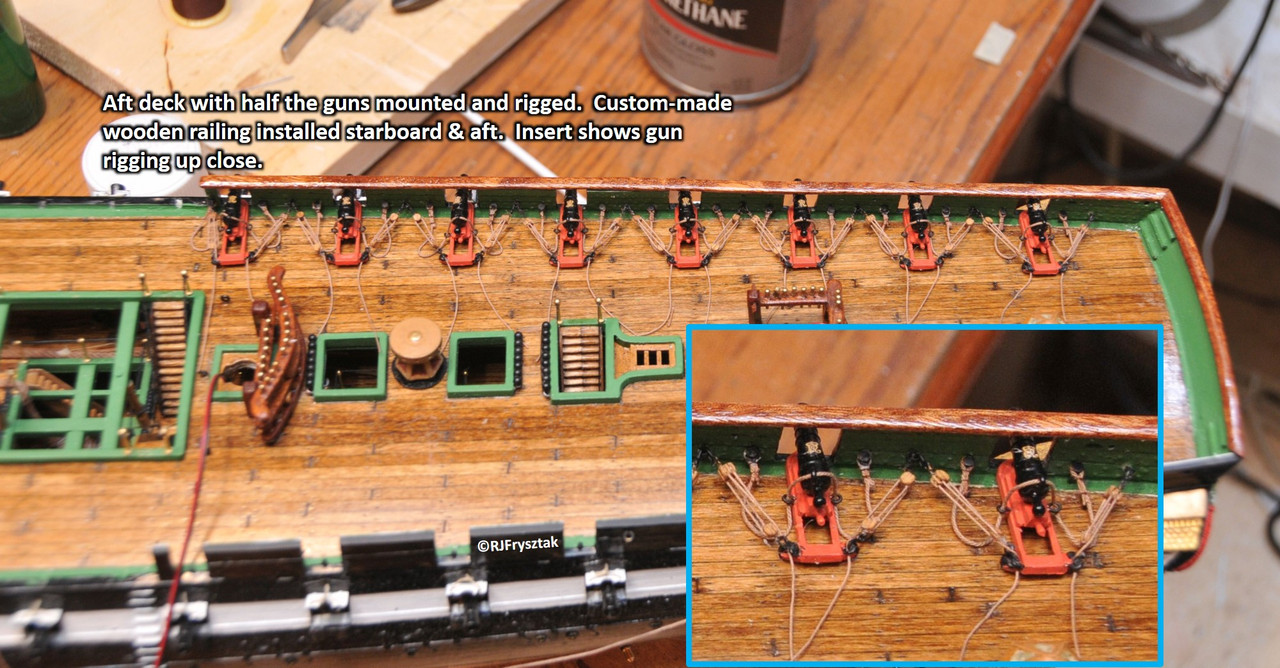
Installed and rigged starboard aft deck caronnades and installed rail.
Need to finish port caronnades and railing, install wheel (still working on this) and the rest of the hardware for rigging the mizzen mast.
Bob
P.S. Went on river cruise through Bordeaux, FR, then spen a week trolling around Tuscany, IT. Had a blast. Waiting for wine to be delivered.
The rumors of my demise are false. Been quite busy with life the past few months. My nephew was married in October, my son got married the week before Thanksgiving (afterwhich we ended up dog-sitting while they were on their honeymoon) and then the holidays arrived (had 26 people over for Thanksgiving, and 24 for Christmas). So now that all the dogs and people have left, I finally got a chance to get to my workroom. I also decided that since all the Christmas boxes were out, I would do a little cleaning and rearranging. Finally made it “MY” space (instead of a space I just worked in. Got all the new toys I got for Christmas in there as well (new airbrush station, mini-lathe and dremel drill press).
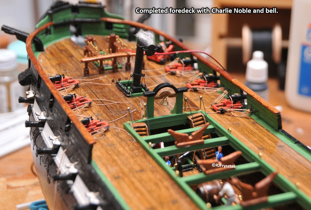
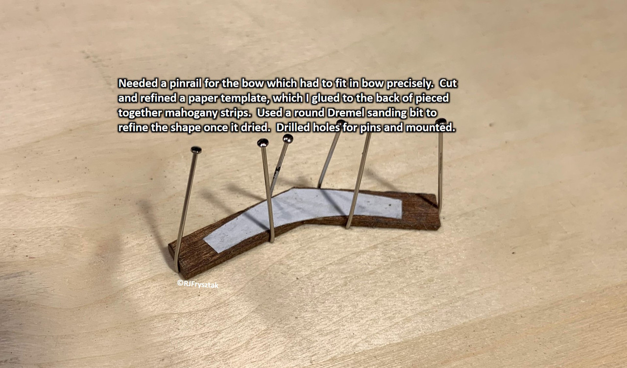
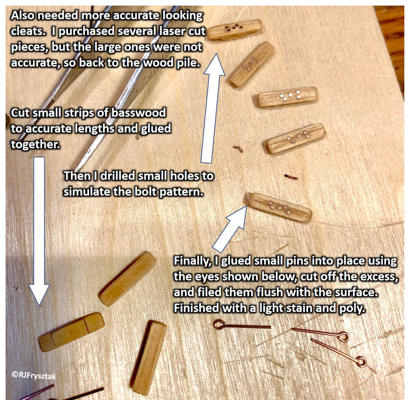
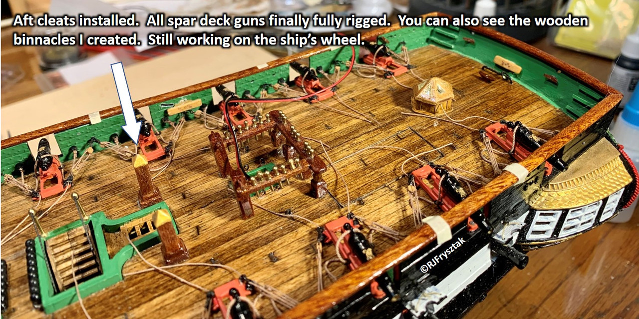
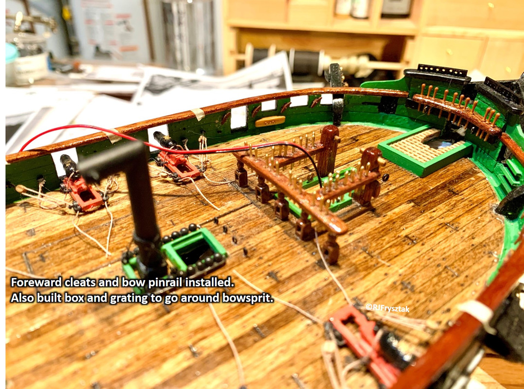
On to the boat! Working on all the remaining spar deck furniture. Built some binnacles since putting those cheap plastic ones on their with all the real wood seemed silly. Finished rigging the last 8 carronades and installed the last piece of mahogany railing. Started working on the cleats and pinrails. Started with the bow rail, since that had to be precisely fitted to the shape of the bow and still have clearance for the bowsprit. Also put a box and grating over the bowsprit since that funky “ladder-like thing” that came with the ship was never really there (just a way to hide the hole in the deck). Got several laser-cut cleats, but the big ones just didn’t look right. So back to the woodpile to make my own. Really wanted the bolts to show, so after making the cleats, I drilled the bolt pattern, pushed through some copper pins, cut off the excess, and then filed them flush with the surface. A bit of light stain and some poly finished them off. Installed them where the museum plans instructed. Installed the laser-cut cleats by pinning them to the walls. Finished up the stern with cleats & rail.
Enjoy!
Bob
Bob,
You’re not just a Pinball Wizard.
“…Finished up the stern with cleats & rail…” Exquisite Work!
Did anyone ever tell you “You’ve got beautiful Cleats”?
I’ve been following. Like you it has been a busy Nov-Dec-Jan. Real glad you have resumed.
Jim.
THANKS NINO !
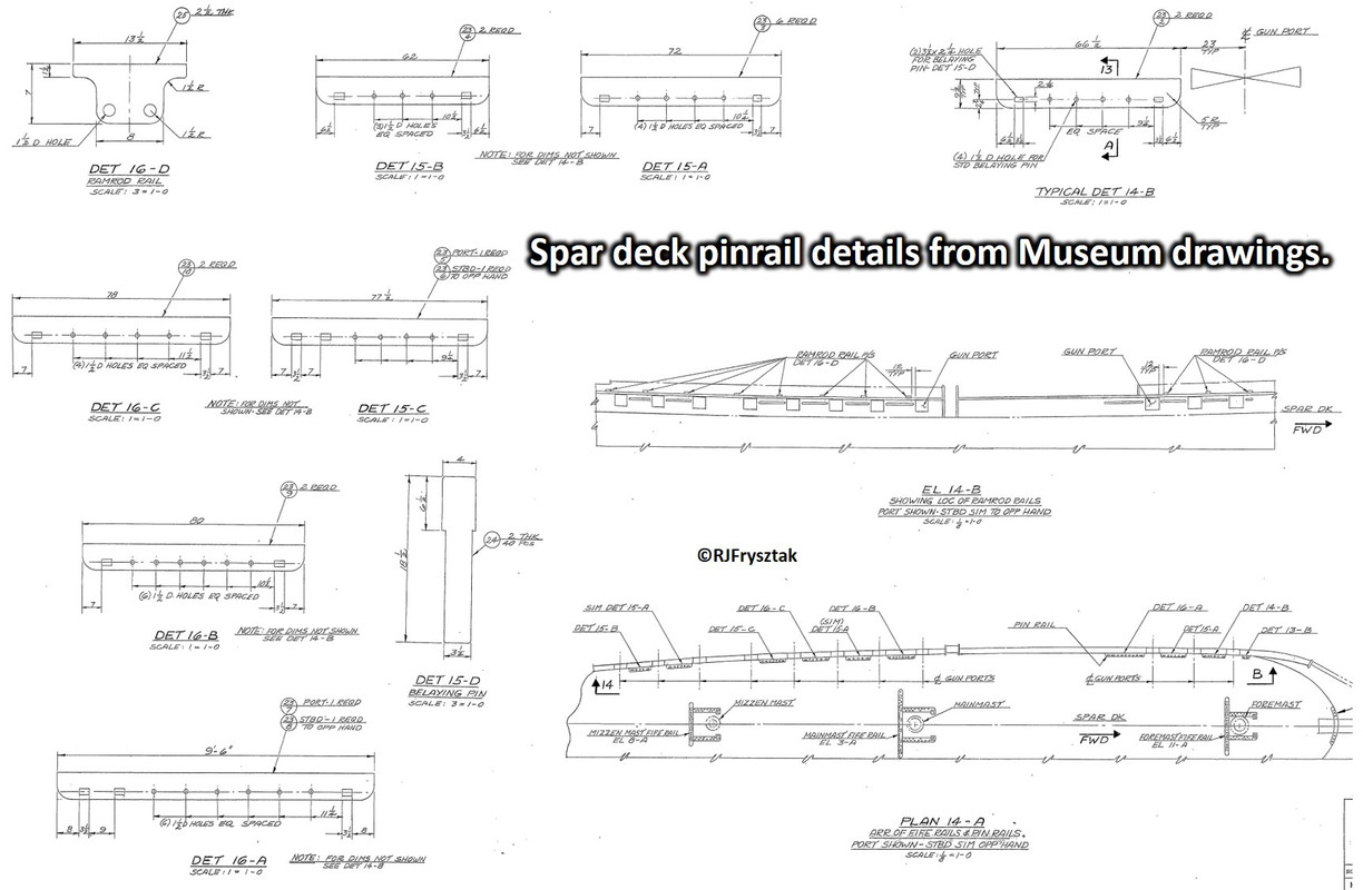
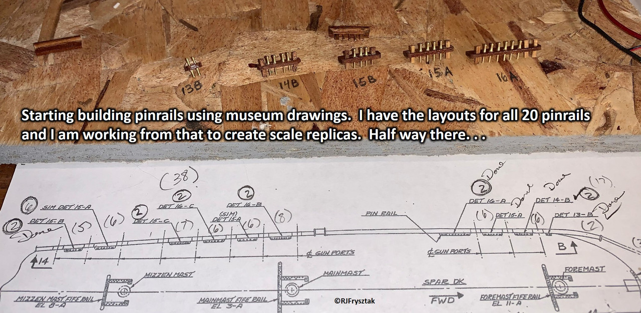
Moving on, I really could not put those frail-looking cheap plastic pinrails on the bulwarks. I also remember all the trouble I had trying to tie off lines to those tiny pins, many of which broke. Even had an entire rail come off half way through rigging. So back to the woodpile we dive!
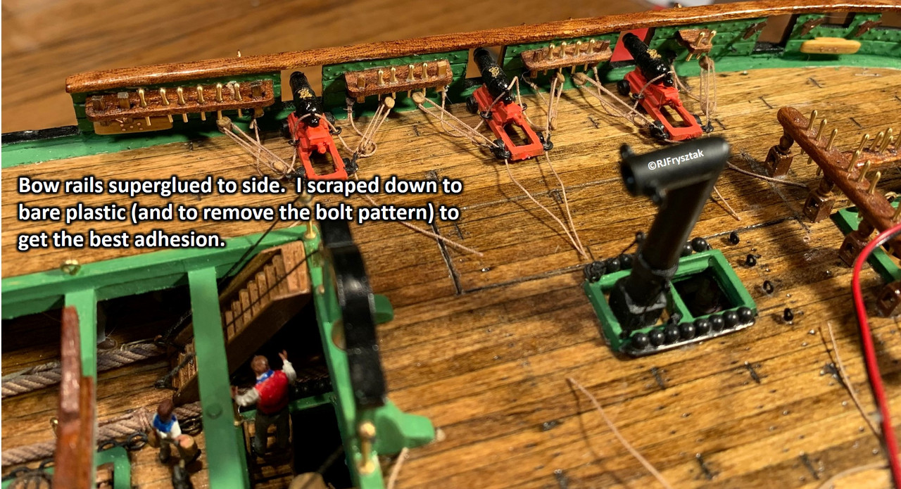
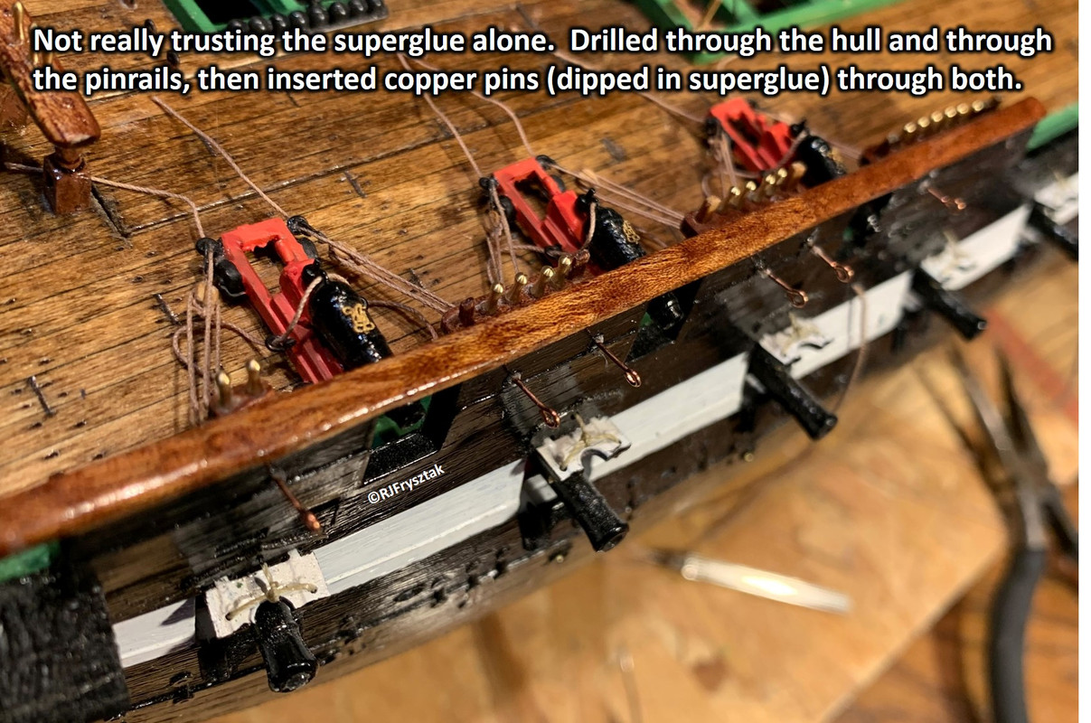
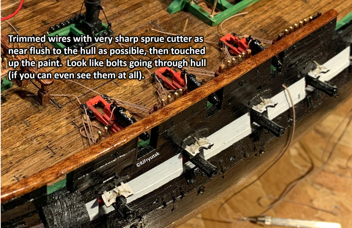
Pulled out some more of the mahogany to match the railings. I glued an extra 1/16" x 1/16" piece to the inside bottom of the rail to give me a larger glue surface. Then using the drawings from the Constitution museum of the rails, I cut the pinrails to scale length, rounded the front edges and drilled all the holes for both the round and square belay pins. Made the square ones from scrap stock, and purchased some of the Model Shipyard brass 9mm pins (will paint them to look like wood later). All belay pins were glued in place, then the bulwarks scraped down to bare plastic (also had to scrape off the bolt pattern added earlier). Mounted with a generous amount of CA. To prevent them from popping off during rigging, I then drilled through the hull and pinrails and installed copper pins. Trimmed flush with hull and painted to blend in. Look like bolt heads, if you can see them at all.
Bob
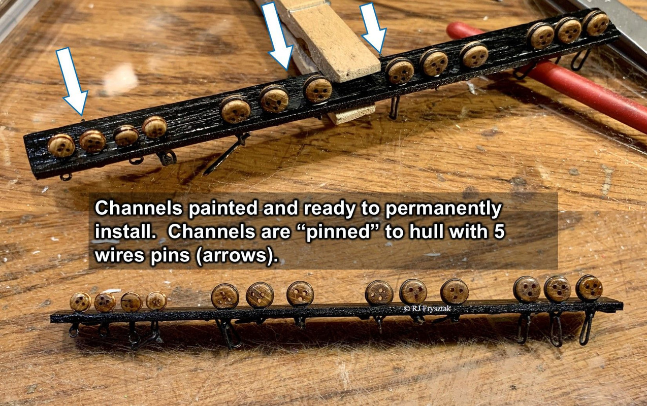
Having completed the pinrails, I have moved on to the channels. Big problem here. Revell’s kit is flat out wrong. Yes, you can use the cheap prefab plastic channels and get away with it. I wanted to go with wood, and realized one important point: Revell did NOT get the gun deck guns and spar deck guns in the right places. What that means is that when you try to figure out where to put the deadeyes and irons, you are left with a VERY limited number of places to comfortably mount them with any kind of even spacing AND having them in the proper alignment to the masts. Using the museum plans as a starting point for the overall size, it is also apparent that the Revell kit took some liberties there also. Anyway, I printed the scale drawings to 1/96 on stiff card stock and cut them out. Glued up several pieces of hardwood to get the width, then traced the patterns and cut out the channels. I also added a thin (1/16x1/16) piece of styrene stock under where the channels would attach to give them something to rest on (and glue to). I also drilled holes in the hull and channels for wire pins to anchor them solidly.
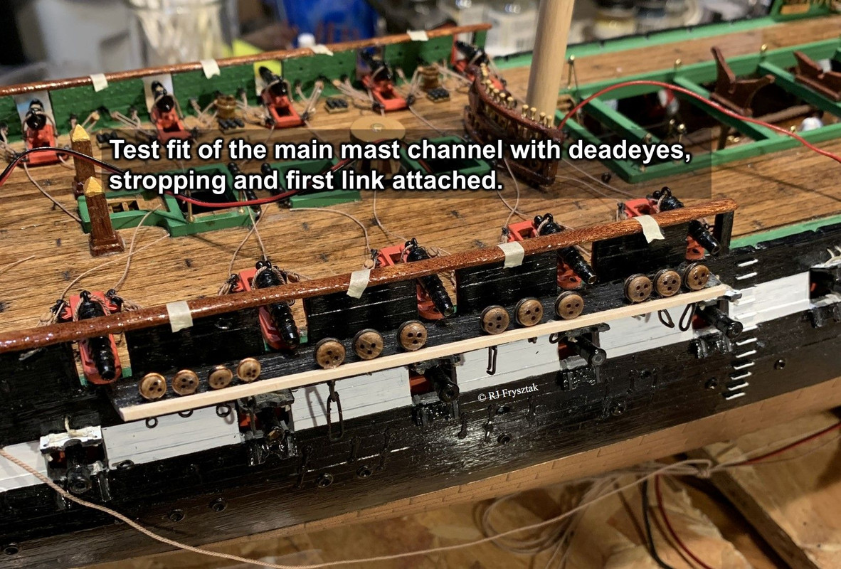
After mounting them temporarily, I put the mast in place and used a string to determine where I could mount the deadeyes. I created a small notch in the edge of the channel, stropped the deadeye, and glued in place. When all the deadeyes were in, I added a wood strip to lock them in. Then painted the channel black. I was able to purchase 5mm iron strops, but made my own for the 3.5 and 2.5mm deadeyes. The first one attached is that for the main mast, shown below.
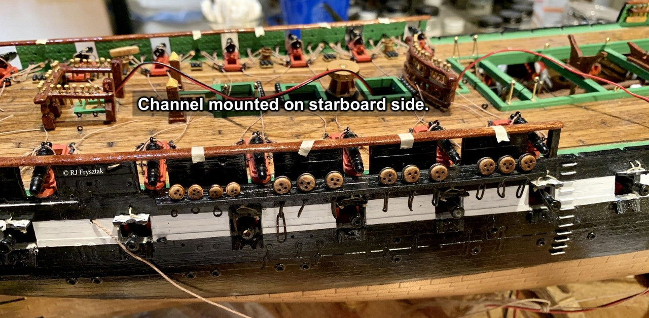
Only 5 more to go!
Bob
Great job Bob…fantastic.
Why not paint the deadeyes…they too needed to be preserved and painting them black would be in keeping with the standard of the day…
Rob
Rob,
I was looking at some of the pictures and paintings and agree with you. Plus it simplifies my painting process, so win-win. Big question: were the ropes used for reeving the deadeyes tarred or not? Current Connie has black (tarred) ropes between the deadeyes, but many of the models I have seen they are tan.
Bob
Bob…good question. The lanyards, as much as some folks want to suggest, are NOT running rigging. Once the shrouds were brought taught…the lanyards were tarred to preserve them. The deadeyes were also painted. Wood and hemp rope were highly suseptible to deterioration. Folks who model the lanyards in tan rope are simply following a false perception…mostly driven by what looks good to them, however it is not accurate.
I trust the nautical engineers and historians who refitted the Connie…their black nylon is representitive of a known practice.
Your model is impressive.
Rob
Thanks Rob! You are the best, and a fountain of nautical knowledge.
Bob