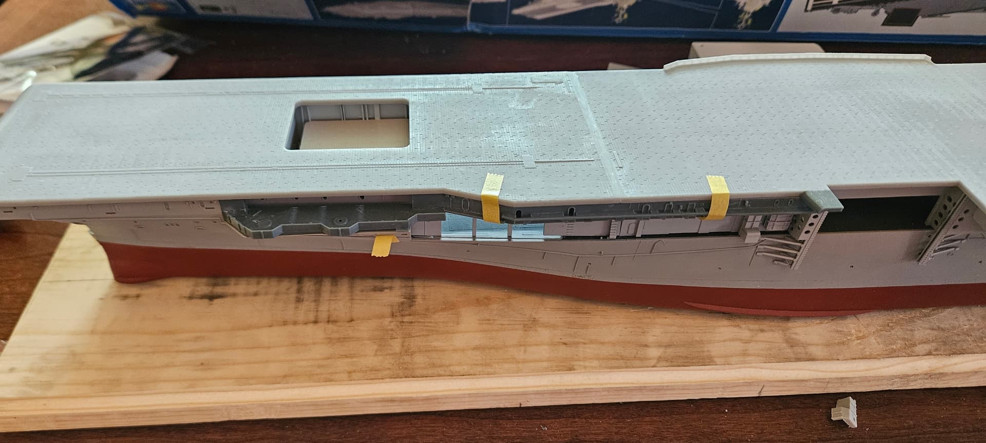
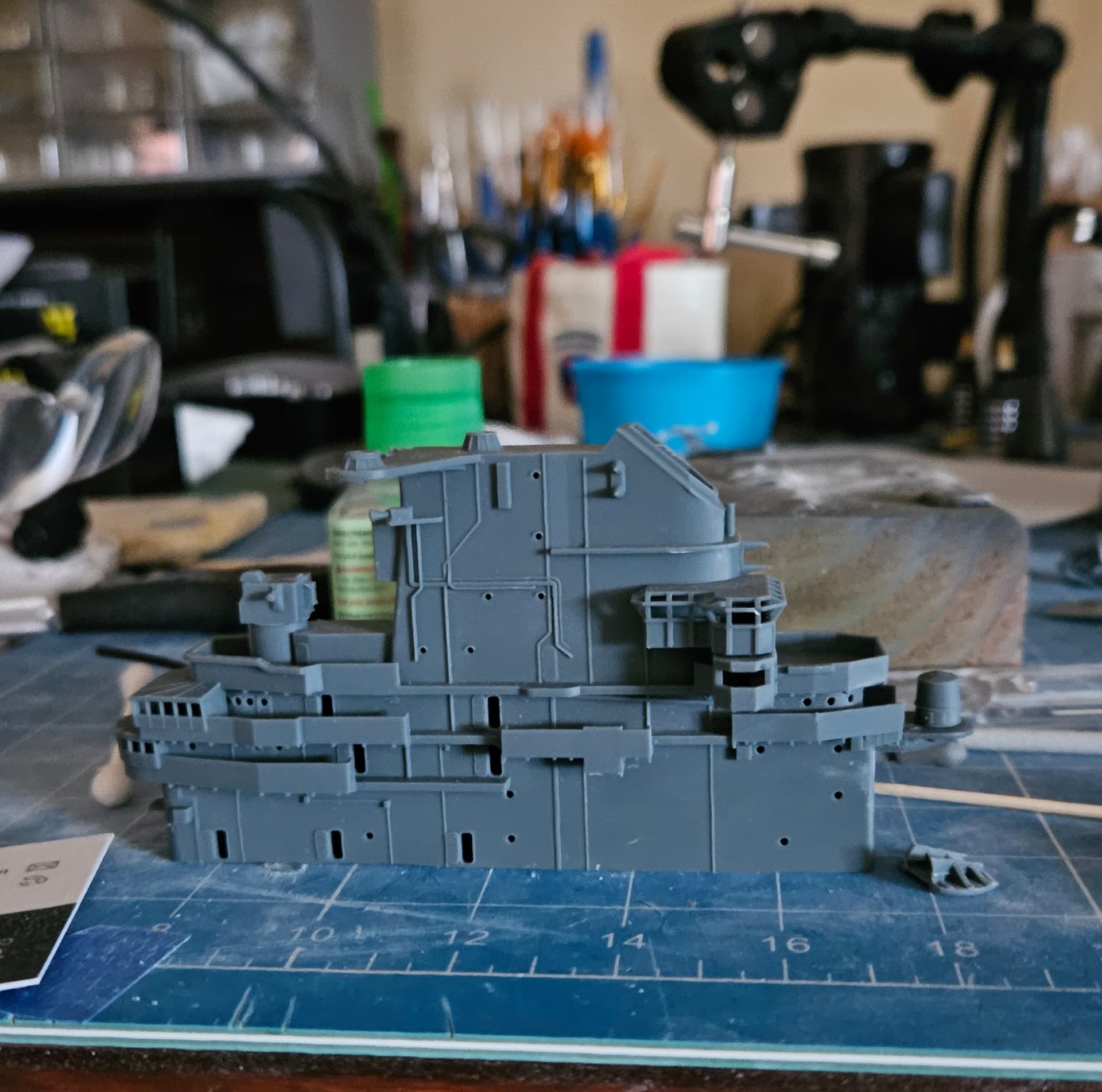
I’ve also been working on the forward port superstructure. The upper portion that fits flush to the flight deck also follows the outline of the flight deck. The slant on the Hornet and Intrepid are different, so I had to redesign that upper portion and print it. Then I was struggling a bit to mate that part to the kit’s gun sponson deck, so I designed and merged the deck with the superstructure part. This is probably the longest part I can print with my 3D printer, and the job took over 16 hours…fortunately, it turned out well and test fitting is satisfactory. There’s a small gap between the gun sponson and the gun sponson deck, but I have printed a shim to insert under the deck and above the sponson to close the gap.

1 Like
Got the new platform test fitted; looking much better, but I think I will add railings to the 3D model, since with the curvature it will be easier to get a nice fit around the radome.
1 Like
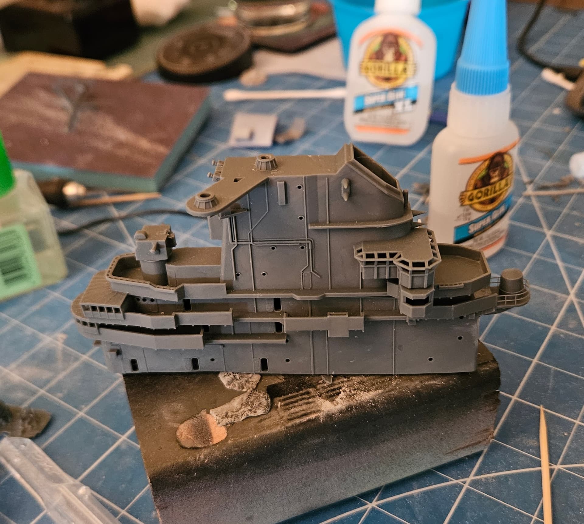
Got the final version of the platform printed and installed today. The railings turned out well, but they are extremely fine and probably just at the limit of what my printer can do.
1 Like
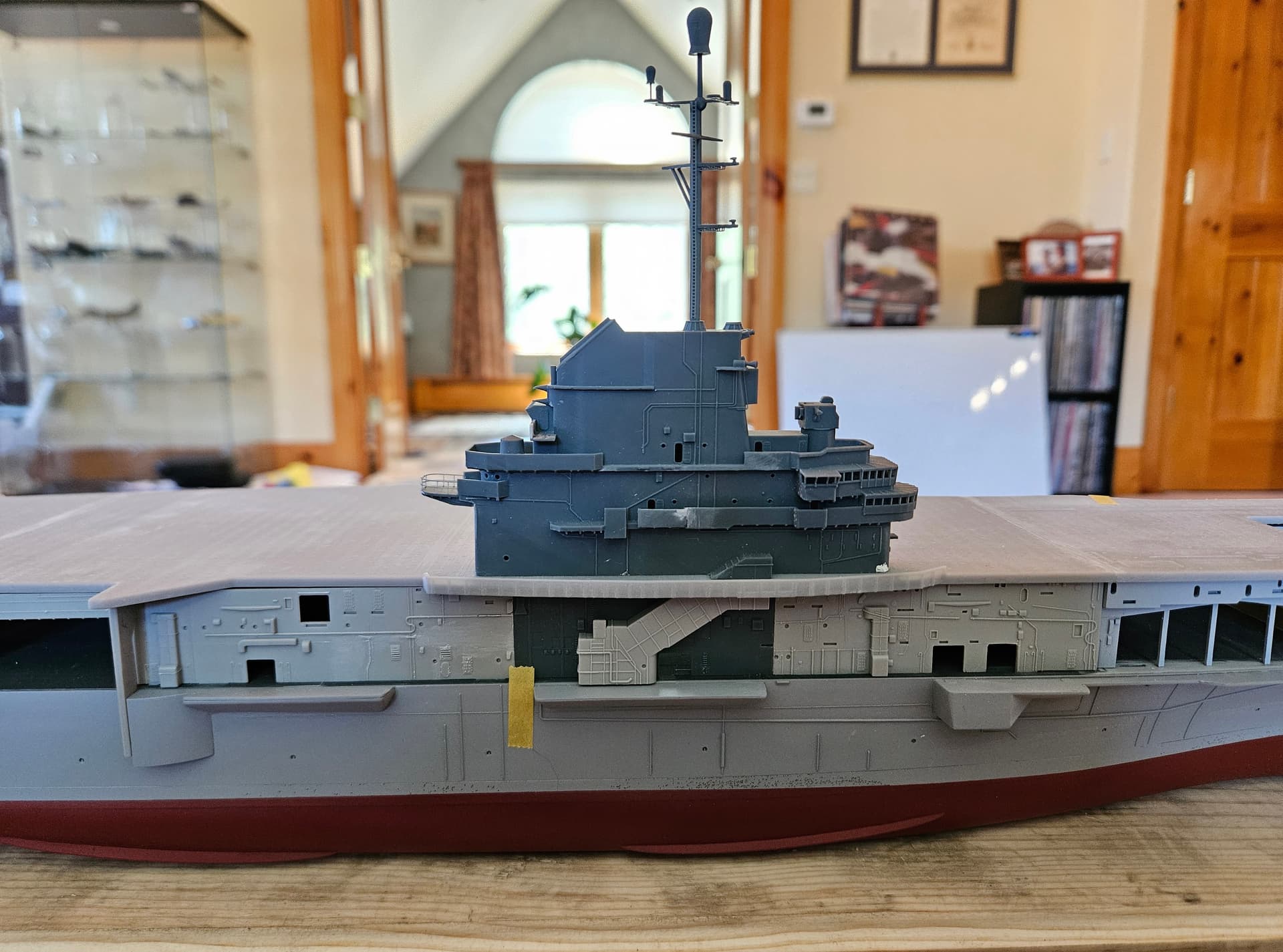
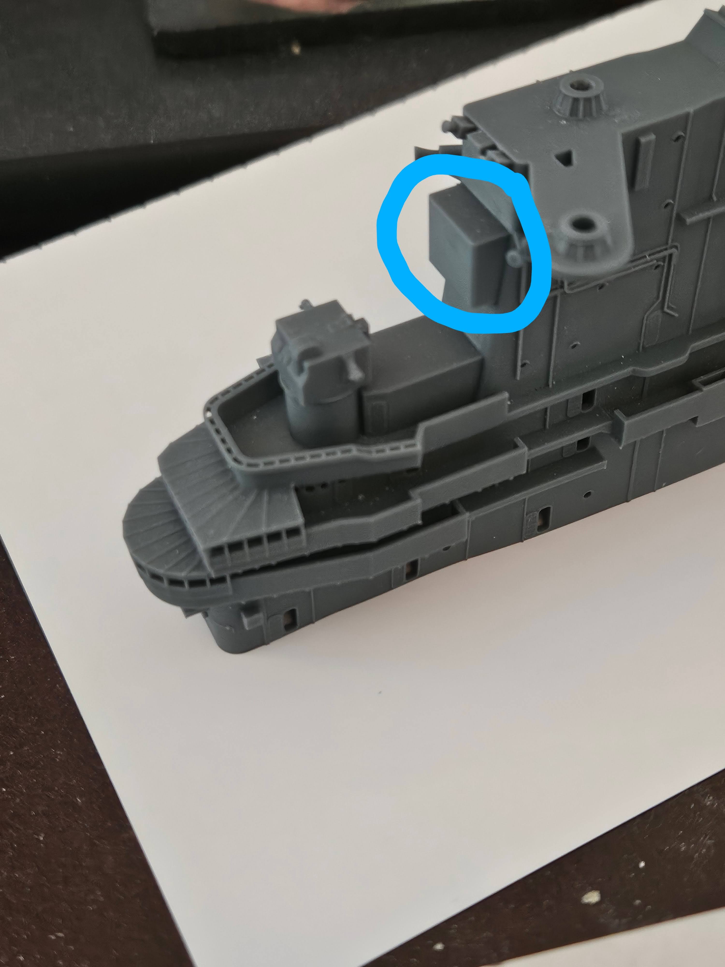
Meanwhile, I just encountered my latest issue. The escalator that carried the pilots to the flight deck has a very prominent enclosure which is part of the superstructure on the starboard side, just below the island. Since the enclosure penetrates the flight deck and is also part of the island, getting the island and superstructure aligned is important, or you will recognize that something is off right away. When I aligned the island on the flight deck with the superstructure dry-fitted below, I realized that the enclosure needs to be about 7.5mm further forward than it was for the Intrepid kit. There’s a lot more detail in this part of the superstructure, so instead of trying to reprint the whole thing, I will first try and get just the section I need printed, and then graft it into the rest of the superstructure. I have designed this section already and am printing as this is being written. I also put a dummy enclosure into my Blender file to ensure the spacing of everything is good, so hopefully we will be in good shape with this print.
Success…the new superstructure component has been grafted in and the escalator enclosure is now where it should be. One thing I learned through trial and error is that if you intend to graft a piece onto kit pieces of the superstructure, install them all first to ensure they remain flush to the hangar deck. I did not do this the first time and the forward most piece ended up pointing up at a slight angle, creating a gap in the join to the deck.
2 Likes
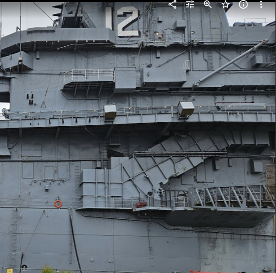
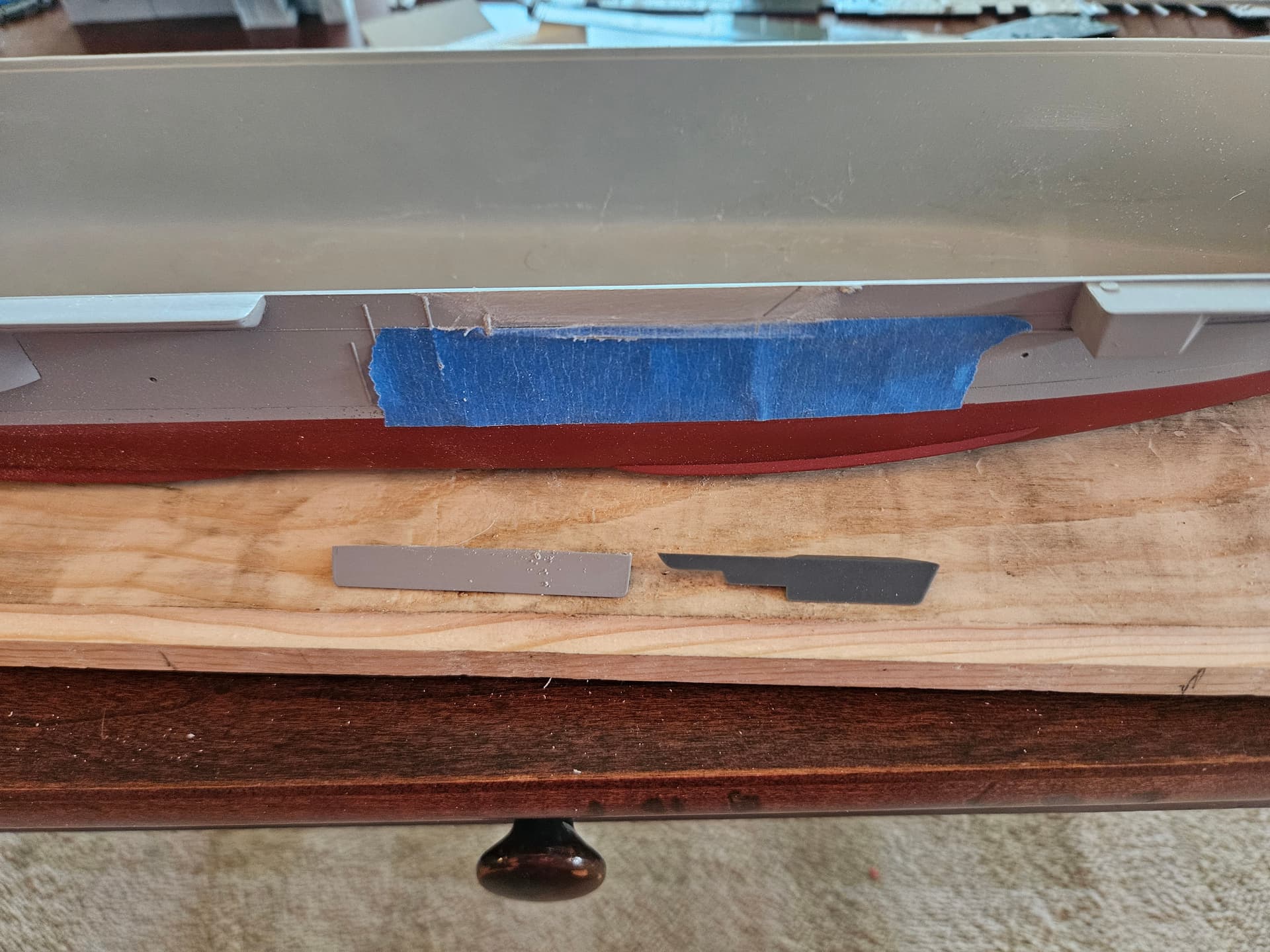
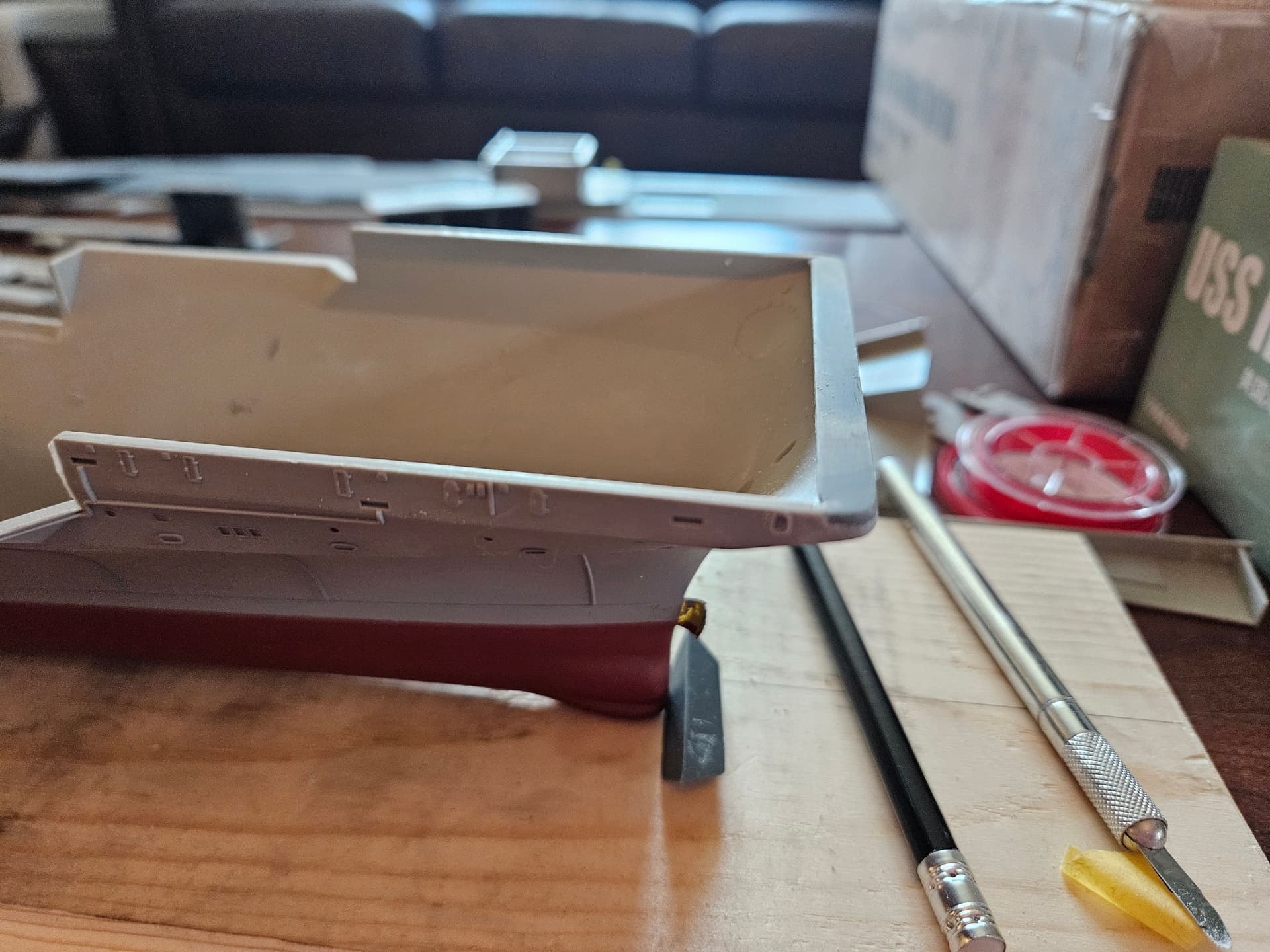
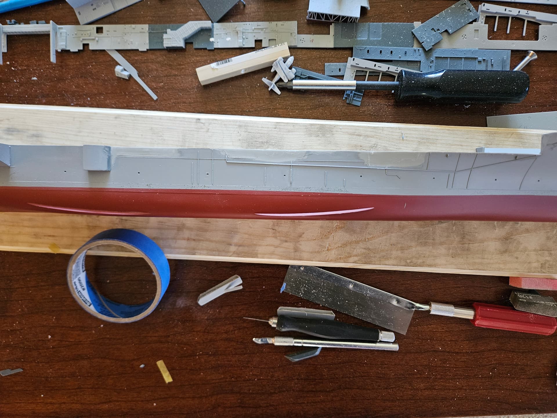
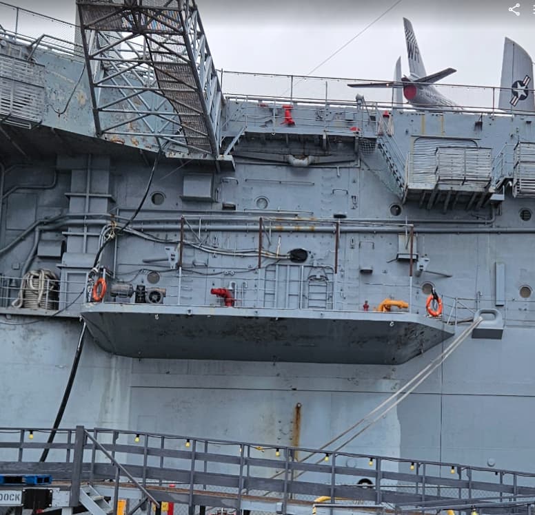
I decided that I needed to think through the assembly process, as I’m almost done with the major design changes to the kit, at least at the superstructure level, so I created this assembly guide to make sure I get things done in (what I hope is) the right order. Since my focus is now on getting the hull sorted before I paint the upper surfaces, today I printed a shim for the forward-most part of the bow. The kit has a slight step-down that helps with aligning the kit’s flight deck. As mine is flush, I needed to fill the gap. Fortunately, I have that shape in my inventory already from the flight deck work, so I cut a thinner slice of that cap and inserted it, fixing it with a combination of epoxy and CA. Also, after further review when I was working on the escalator enclosure, I noticed that the shape of that unrep sponson was quite different than what came in the kit. Having gone this far in the pursuit of accuracy, I designed and printed the sponson in the correct shape from the plans I have for the Hornet, and cross-checked them against my photos. After some very careful work with the razor saw, sanding sponges, and files, I got the scars removed and the new sponson fitted. I might be the only one that notices these small details, but I feel good about getting it right.
Actual sponson on Hornet:
Old sponson on left, new one on right. Scars on hull carefully sanded down and piping detail protected by blue tape. I will be re-priming after all touchup work is done:
Newly fitted sponson:

Spacer fitted and sanded for bow:
1 Like
Stay tuned…I re-checked the remaining sponsons, and they’re all wrong! I will be designing, printing and reinstalling the others as well…watch this space!
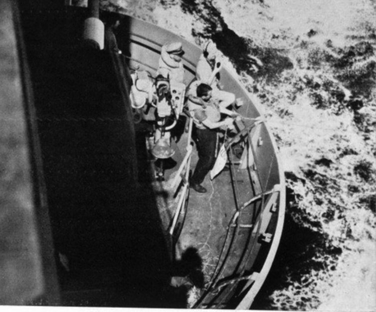
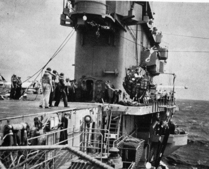
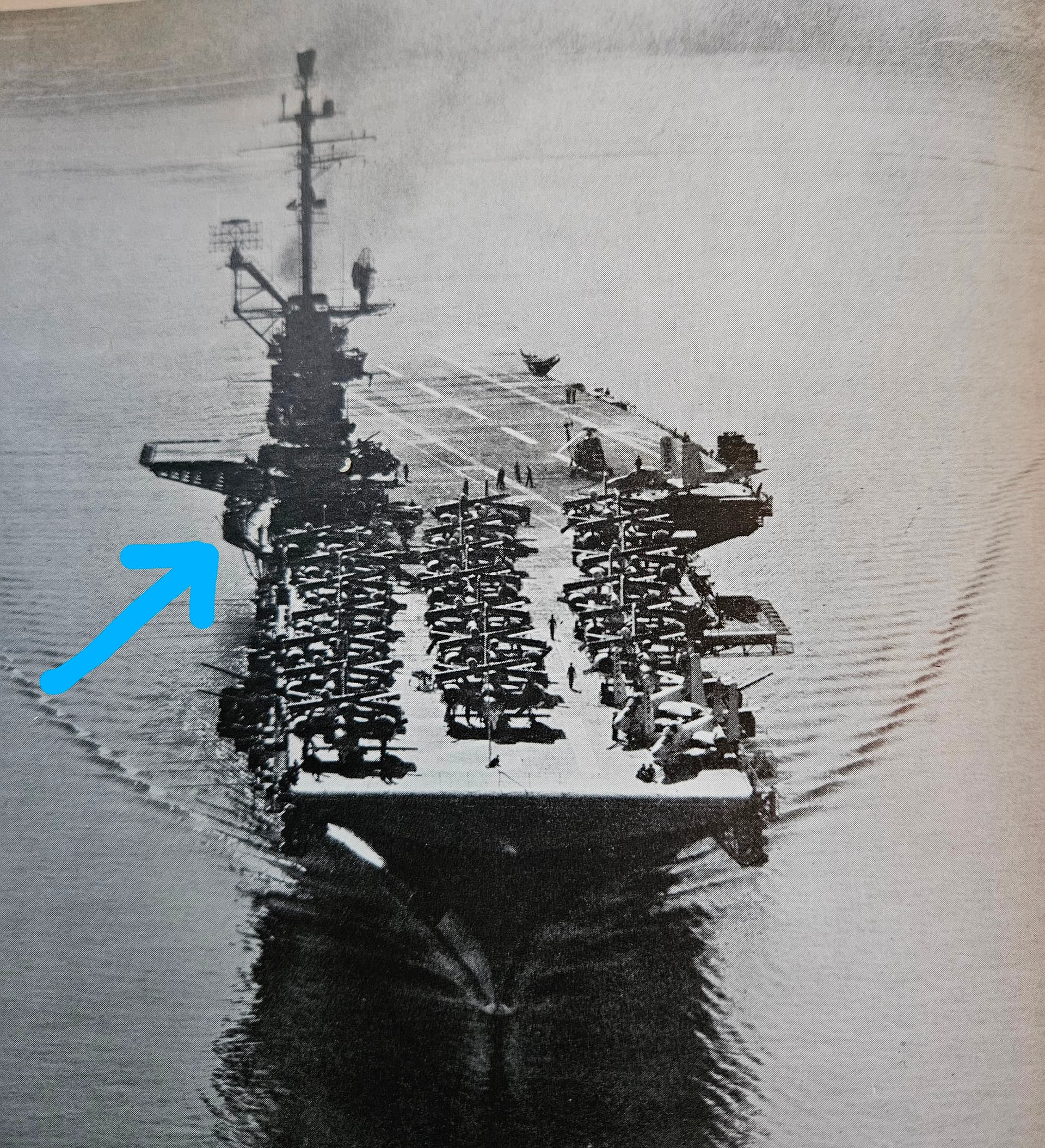
Happy 4th and 250th to everyone! Looks like it was quite a show in NYC today; here in Colorado, we’re celebrating, but cautiously due to the fire danger. So, I’ve been doing more research today, and I learned something important. In my previous post, I mentioned doing the sponsons for the Hornet, as they differed from the Intrepid. Well, after looking at my 1959 cruise book, I noticed something, namely, that there were no visible sponsons on the starboard side, but instead it appeared that there were small platforms to assist with the UNREPs. This got me looking to confirm the layout and I went online to the great navsite.de page to consult the 1958 and 1957 Hornet Cruise Books. Lo and behold, I finally found what I was looking for in this great shot from the 1957 Cruise Book. Thank you, Supply Department. It’s clear in this shot that there were no sponsons at the deck level, but there is in fact a sponson of sorts under the island, just forward of the escalator enclosure. The 1957 cruise book has an awesome UNREP section, and I was able to get pictures of this command and control sponson from all angles. Knowing the rate of change and evolution of the Essex class during this time, just because it was there in 1957 did not mean it would be there in 1959. I did find compelling enough evidence of its presence in 1959 from that cruise book in a bow-on shot. So, I made reasonable guesstimates of the size of the sponson and am doing a test print now. I will also be removing the deck-level sponsons and instead will fit small platforms where the sponsons would be installed later, most likely during the 1961 refit at Puget Sound NSY. I have enjoyed the detective work to get this configuration right. There does not seem to be a definitive source for this configuration, so it’s up to me to create it!
Nice shot of the starboard side, circa 1957. Note no sponson bulges in sight:
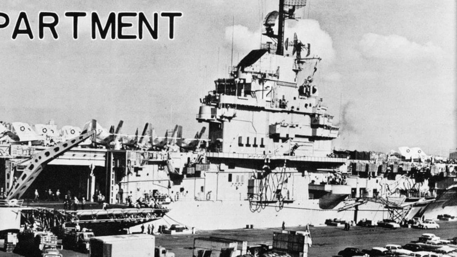
Here’s a great shot from the same cruise book of the UNREP C&C sponson looking aft:
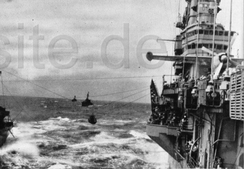
Another shot looking down on the sponson:
And one more looking forward at the sponson:
The piece of evidence that I believe confirms this configuration. Bow shot from the 1959 Cruise Book, which shows almost definitively this C&C sponson:
3 Likes
I am not a huge fan of working with photoetch, so I decided to try and print the elevators with their complete underside structure in place as a single piece. I’ll know in about 7 hours how it went…here’s the design in Blender:
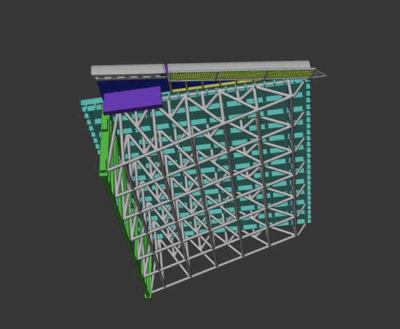
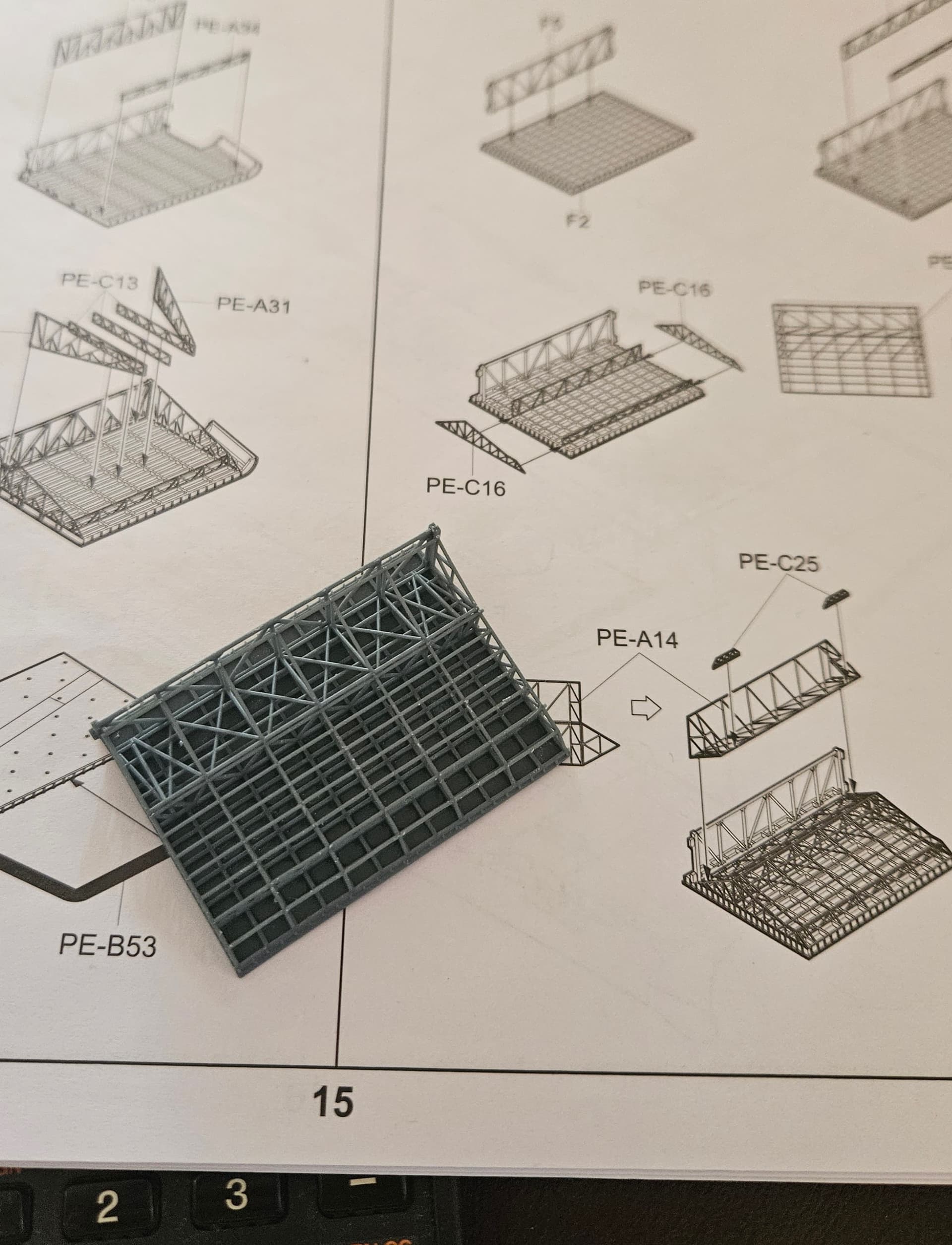
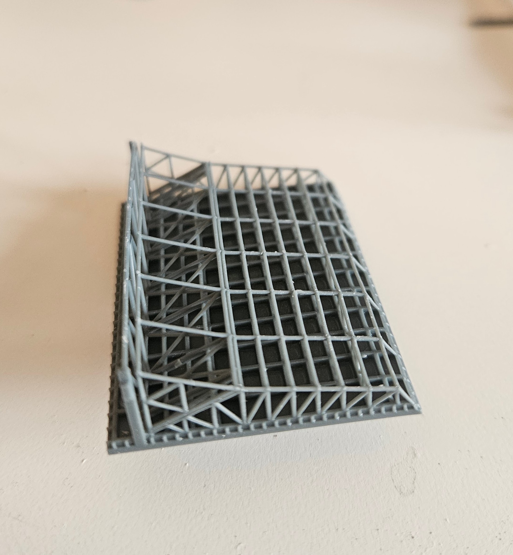
The #3 elevator turned out great, the second time.  I forgot some key supports on the first print, so I corrected and kicked off an overnight run. The results greeted me this morning and I’m very happy with the print. I put the entire elevator in a cage to absorb the peel forces and to protect the fine truss structure, which is only .5mm in diameter. I think it looks far better than PE, since the trusses are actually round as on the original vs. the 2D PE pieces. No fiddling with alignment, super glue and accelerator, either!
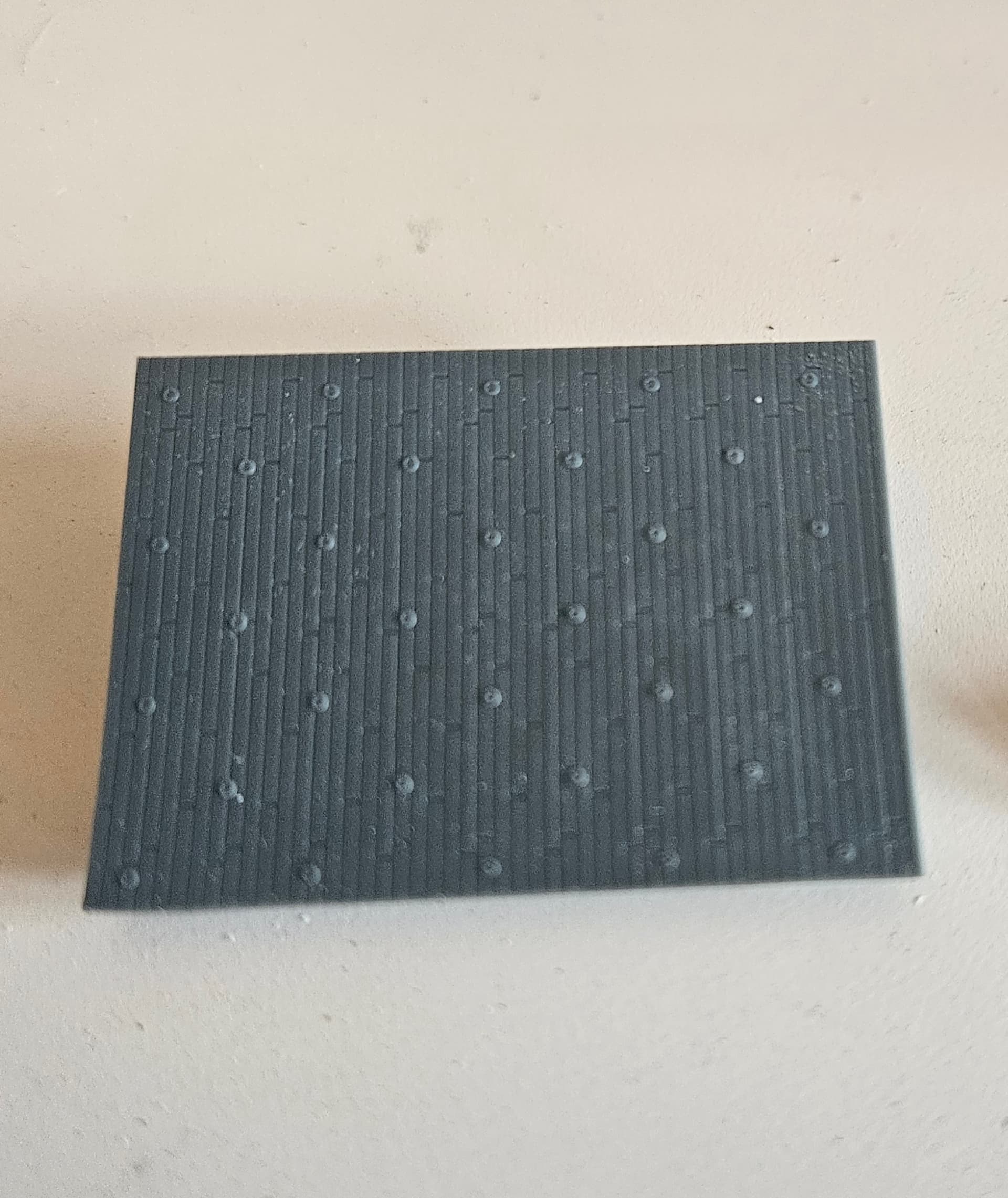
3 Likes
Wow, I just realized I started this thread a year ago. And while I’ve made much progress with research and designing and printing conversion parts, I really have not glued many things together yet! I’m hoping that changes shortly, as I think I have overcome most of the differences identified by my research. I’m now printing the full elevator #2, after which I’ll prime both elevators. I need to remove the remaining sponsons on the starboard side and then print some smaller platforms that seemed to be used for the UNREPs in this era. The UNREP C&C Sponson turned out well and I test fitted it to the superstructure. Since there are no drawings with this sponson, and it no longer exists on the actual ship, I guesstimated the dimensions, but I feel like they are representative enough in 1:350 scale. For those who have read this thread, you probably know that I’d prefer 100% accuracy, but I’ll make do this time! 
Here are some shots of the finished sponson:
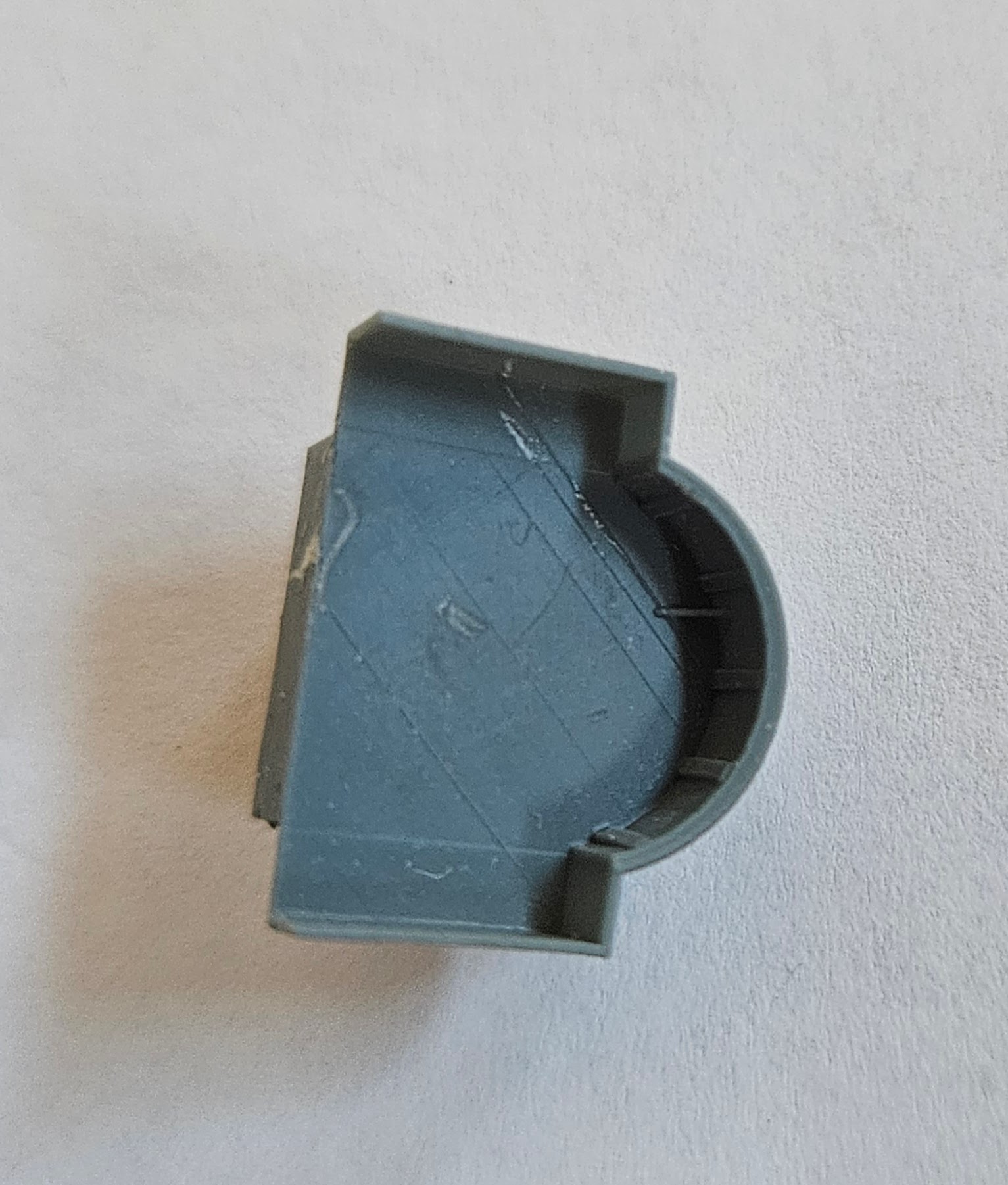
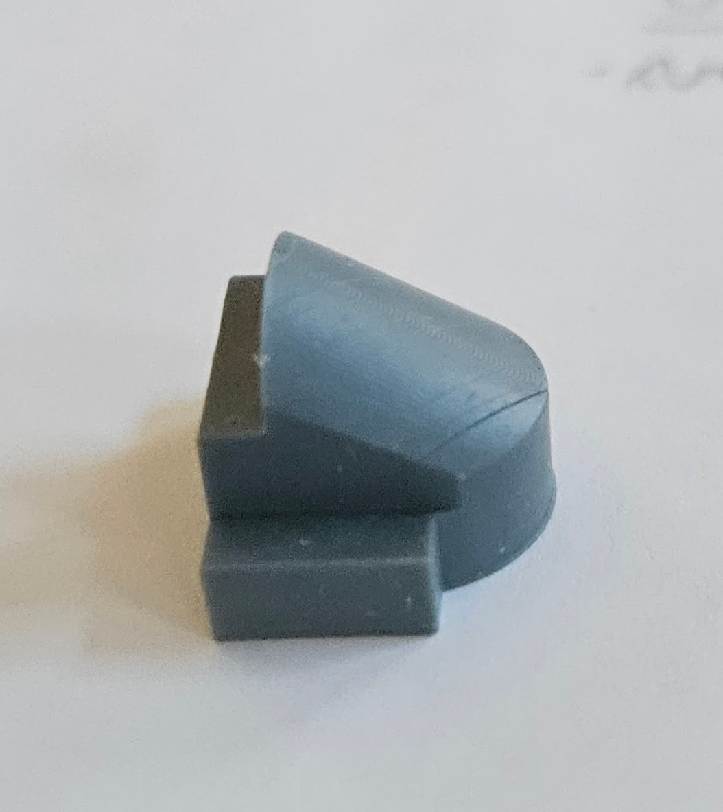
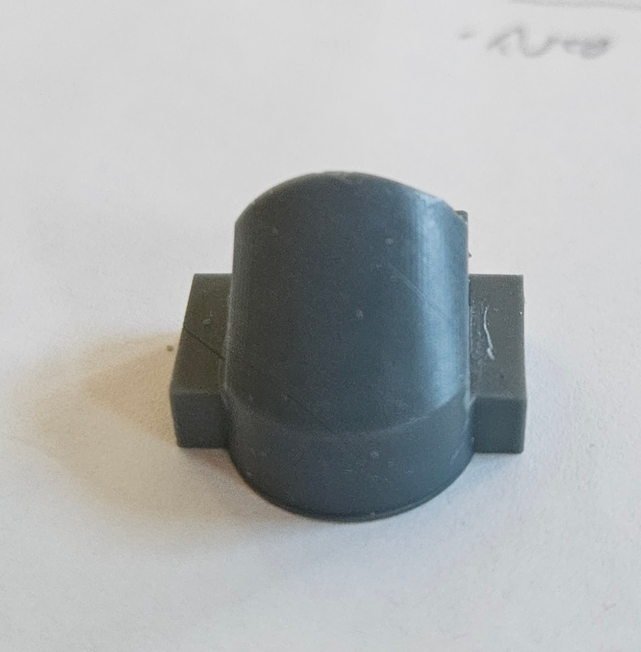
2 Likes
I got the #3 elevator fitted and it looks great. Next up, primer. I also managed to remove all the sponsons. It was not an enjoyable task and I will have to touch up the red hull paint in a number of areas as a result. I will do that, then prime and check the upper surfaces for any defects before installing the smaller platforms.
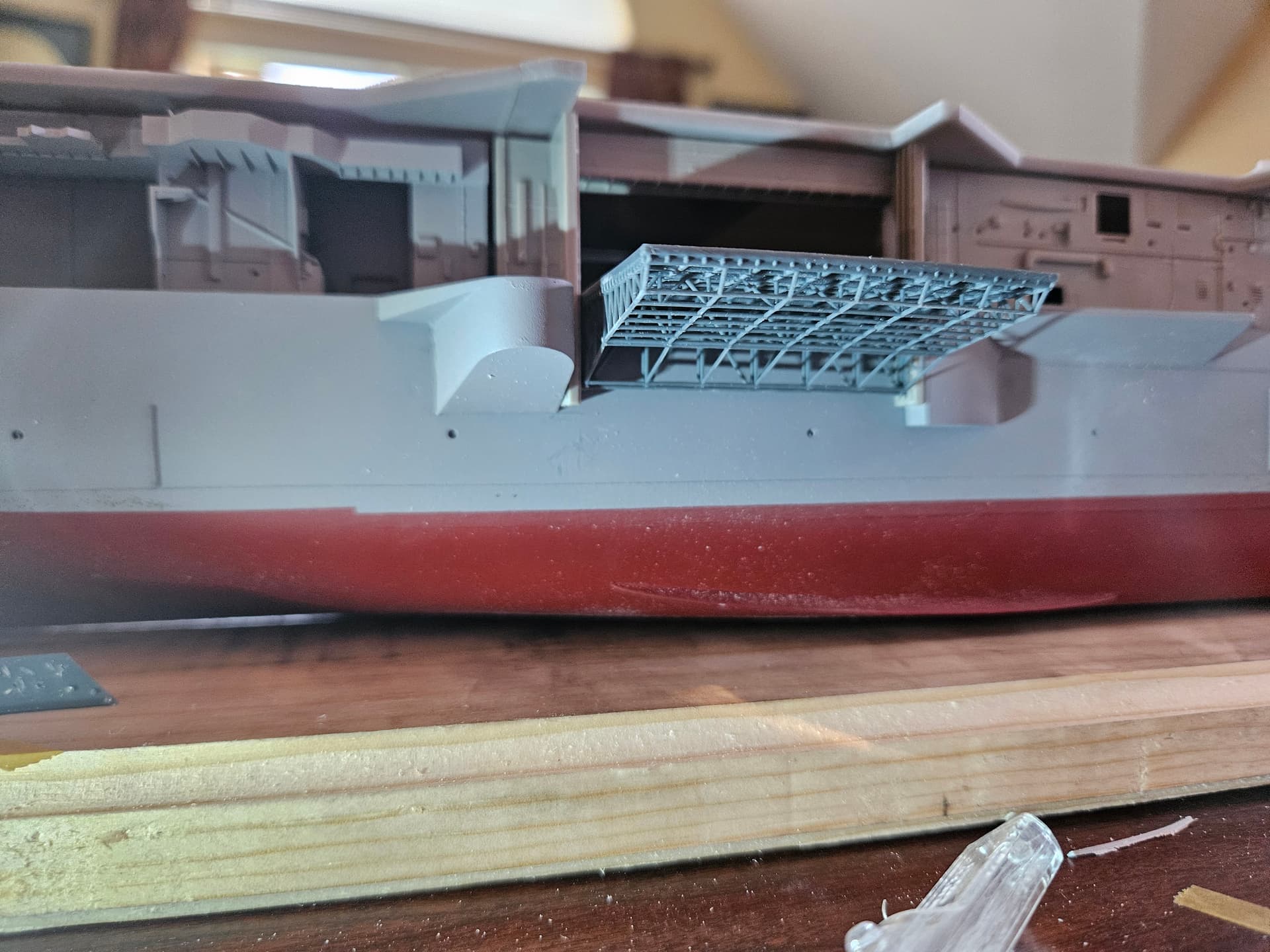
2 Likes
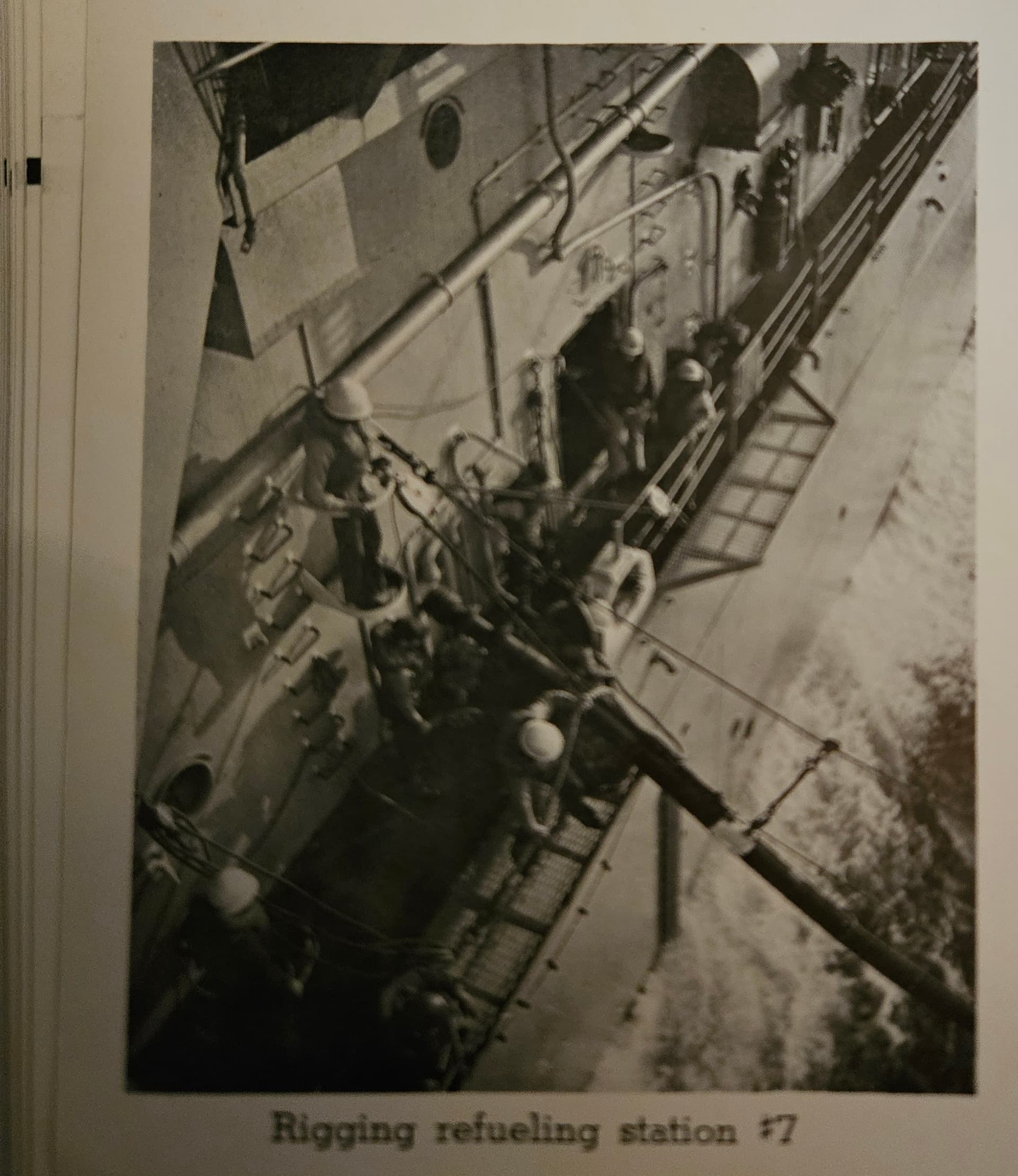
I believe I found the key photo to help me with the UNREP platform design. This is from the 1959 cruise book, so as legit as it gets. The #7 refueling station is just forward of #3 elevator, and these platforms are where the larger sponson is present on the Hornet after the 1962 PSNSY availability. For those really into the details, it looks to me like the chock was moved further forward when the new sponson was installed.
1 Like
incomplete set of drawings CVS-12 USS Hornet Booklet of General Plans (19XX) USA - CVS-12 USS Hornet Booklet of General Plans (19XX) : Bureau of Construction & Repair, Navy Department, Washington DC : Free Download, Borrow, and Streaming : Internet Archive
Thanks! I have these plans and they are for the Hornet post PSNSY overhaul, which occurred after the 1959 cruise. These are excellent references that I have used for many of the components that did not change (or noticeably change). For anyone building the Apollo 11 recovery configuration, these are essential and the gold standard. I do in fact use these daily to check dimensions, etc. I think when I’m done, I’ll produce a document to summarize this 1959 configuration and how it differs from before/after.
So, a few updates to share. I researched the UNREP sponsons to the best of my ability for the 1959 configuration. It is very clear that there are no real ‘bulges’–those came later in what I think was the 1962 overhaul at Puget Sound NSY. Therefore, my photos from the Hornet itself are not super helpful for this, so I once again turned to the cruise book from 1959 and from 1960. These confirmed general size/shape/locaton, so I designed and printed what I think are decent representations of these sponsons.
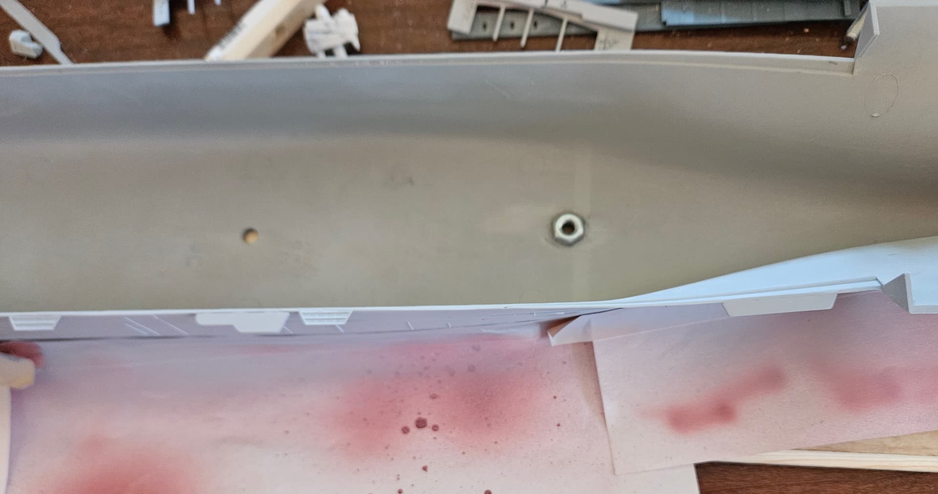
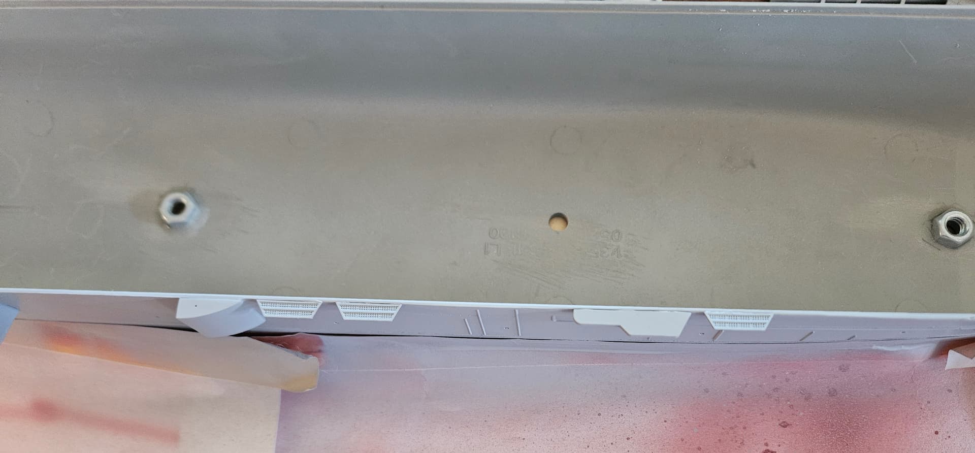
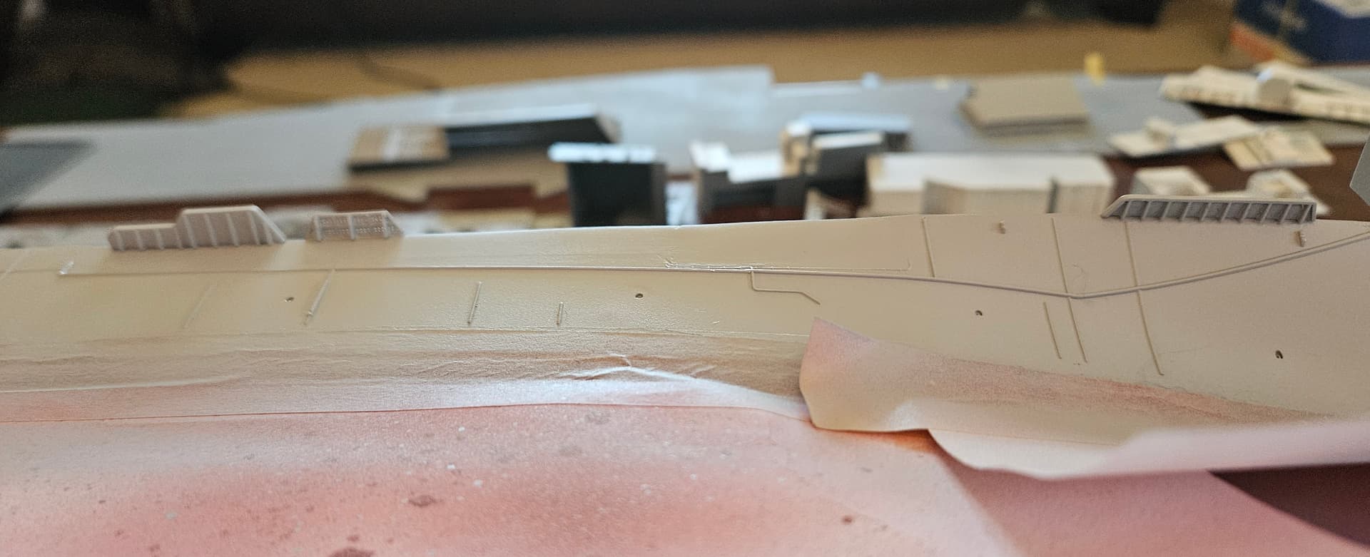
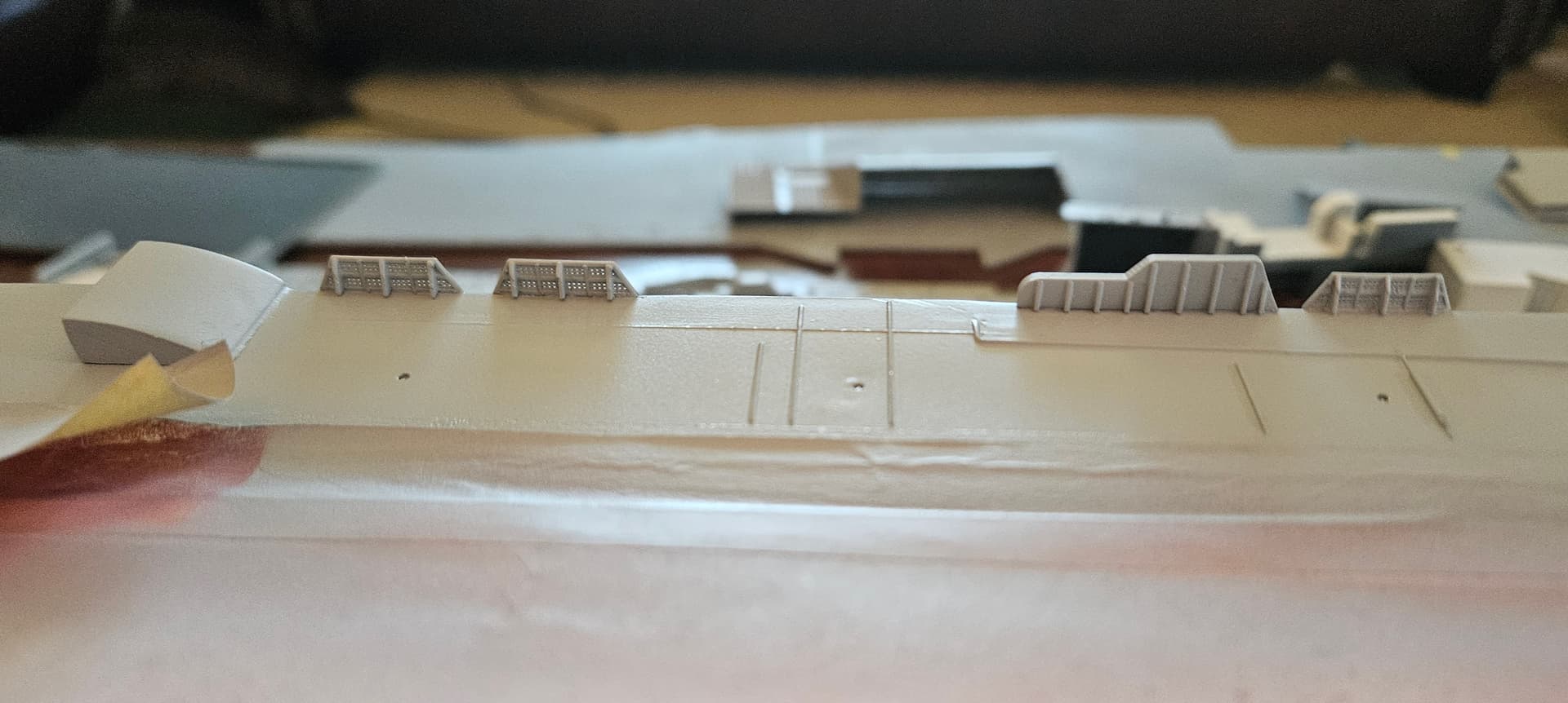
2 Likes
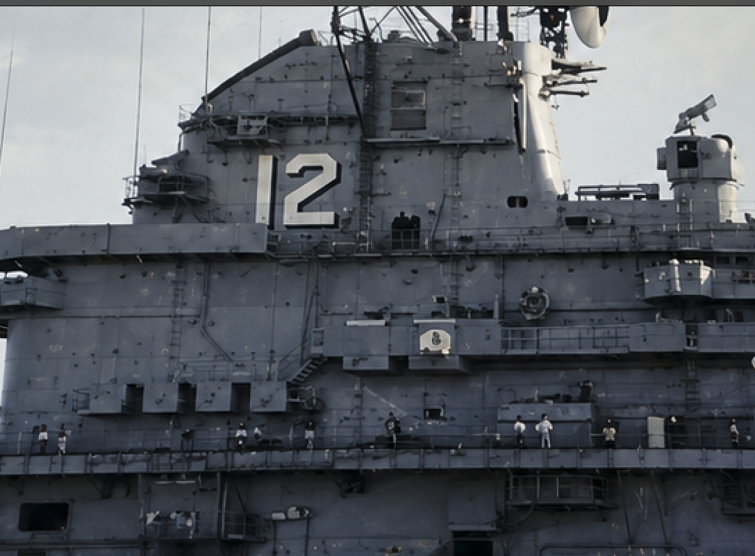
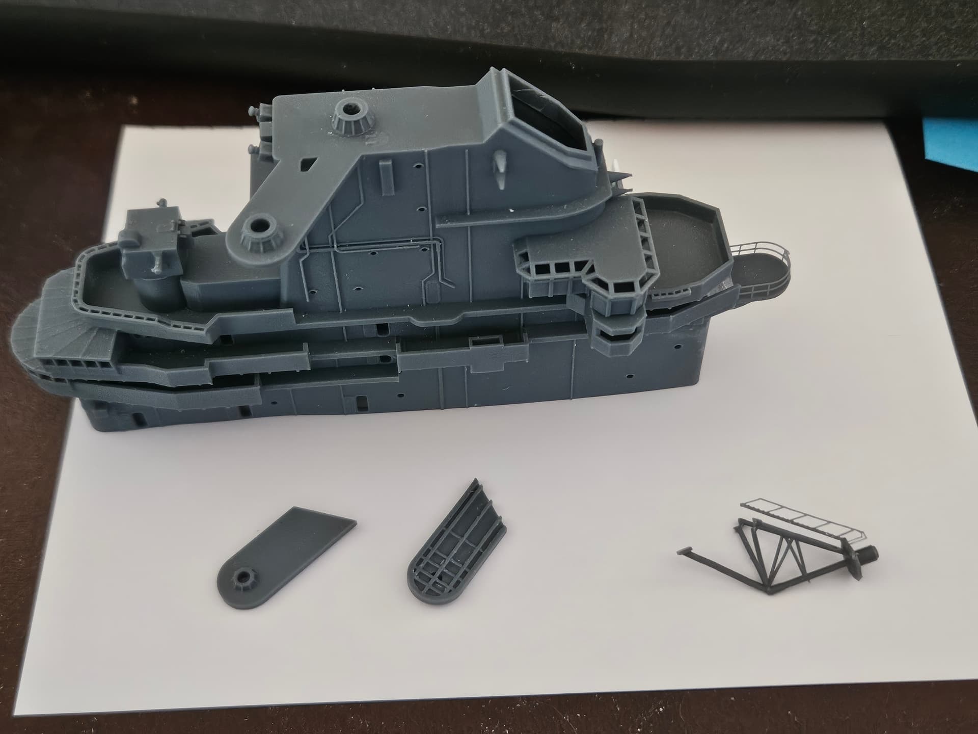
Also, while starting to do more research on the island itself, I discovered a pretty major discrepancy between the Model Monkey Hornet island and how the island was configured in 1959. The Model Monkey island is for the Apollo 11 recovery era–1969–and it turns out there were some noticeable changes there, besides the SPN-6 being replaced by the SPN-35. And though I was able to make that change, there is a considerably more tricky difference on the forward portion of the tallest section of the island–namely, a large rectangular box that sits on that face for the 1969 version, but is not present in 1959. Given the prominence of this piece and the trickiness of trying to remove the box, I looked at the other Model Monkey offerings and determined that the USS Yorktown island for 1955-1960 is, as far as I can tell, a very accurate rendering for the Hornet in 1959, which makes sense. And, bonus, it comes with the SPN-6 already integrated, though it is missing the platform for the SPS-8 height finding radar that is present on the Hornet island. Not to worry, I designed and printed my own platform, along with the mast for the SPS-29 radar on the starboard side of the island. The kit has this in PE, but it will look 2D on the ship, so I opted for printing it as well. It’s a bit delicate, but I feel I should be able to get it in place without too much fiddling. I tried to print the railing around the radar antenna platform, but it was a bit too fine for my printer to replicate.
Good shot of the island from 1959:
The Model Monkey 1969 Island:
My platforms alongside the 1969 Hornet Island:
2 Likes
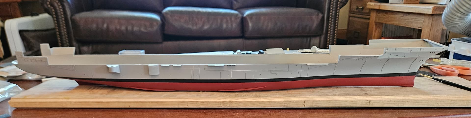
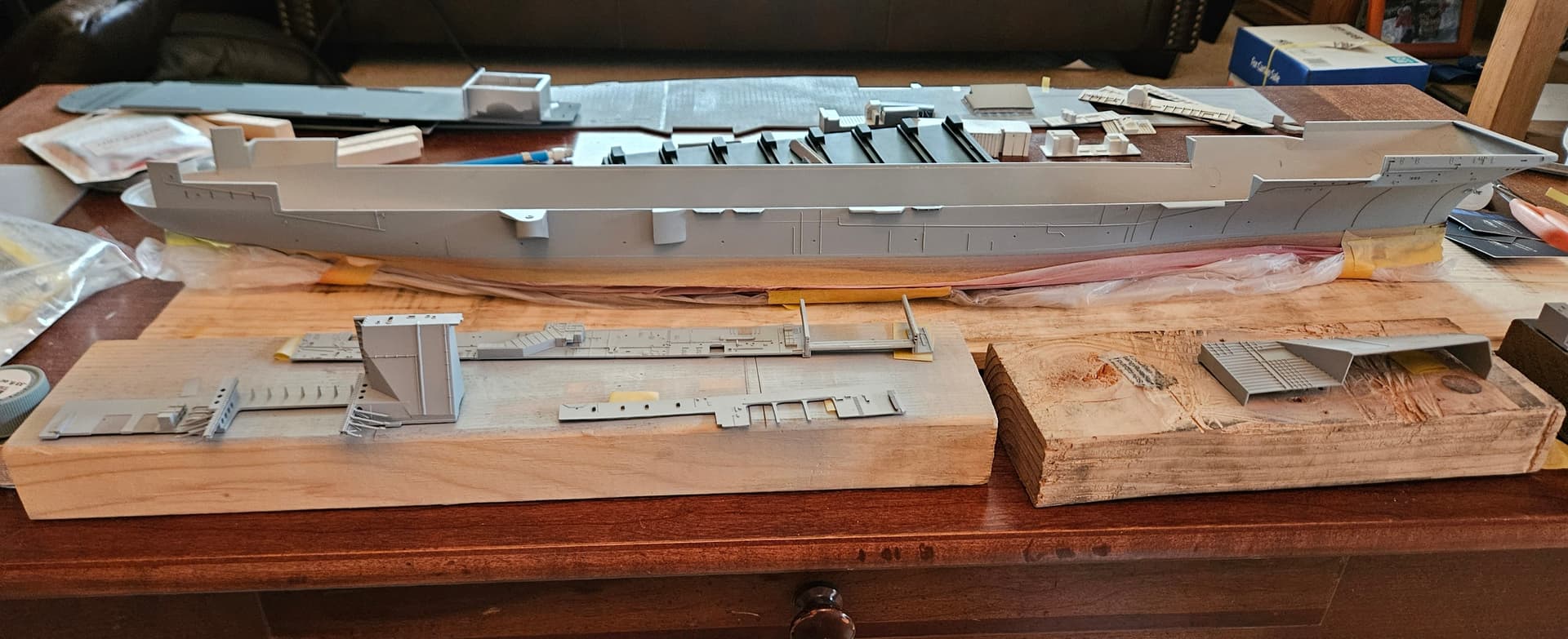
I’m getting closer to gluing parts! Today, I painted the upper hull and most of the superstructure parts. I prefer Light Ghost Gray, as I feel that the Haze Gray paints are missing some of the blue tint that I believe the eye visually registers when you see these ships in person. Years ago, I built a model of my first ship, USS Chandler (DDG-996), while I was still aboard serving as the ASW Officer. I used light ghost gray then and I felt it best represented the ship I was serving on every day, so I’m sticking with it. I do have the Colourcoats Haze Gray in my paint locker, and I’ll probably use it on another ship at some point, but I’m pretty happy with this color combo for the Hornet. It’s very, very close to the Tamiya spray can gray primer I used for the base coat. Hopefully, tomorrow I can reveal the boot topping, which has been hiding under the Tamiya tape for many, many months!
1 Like
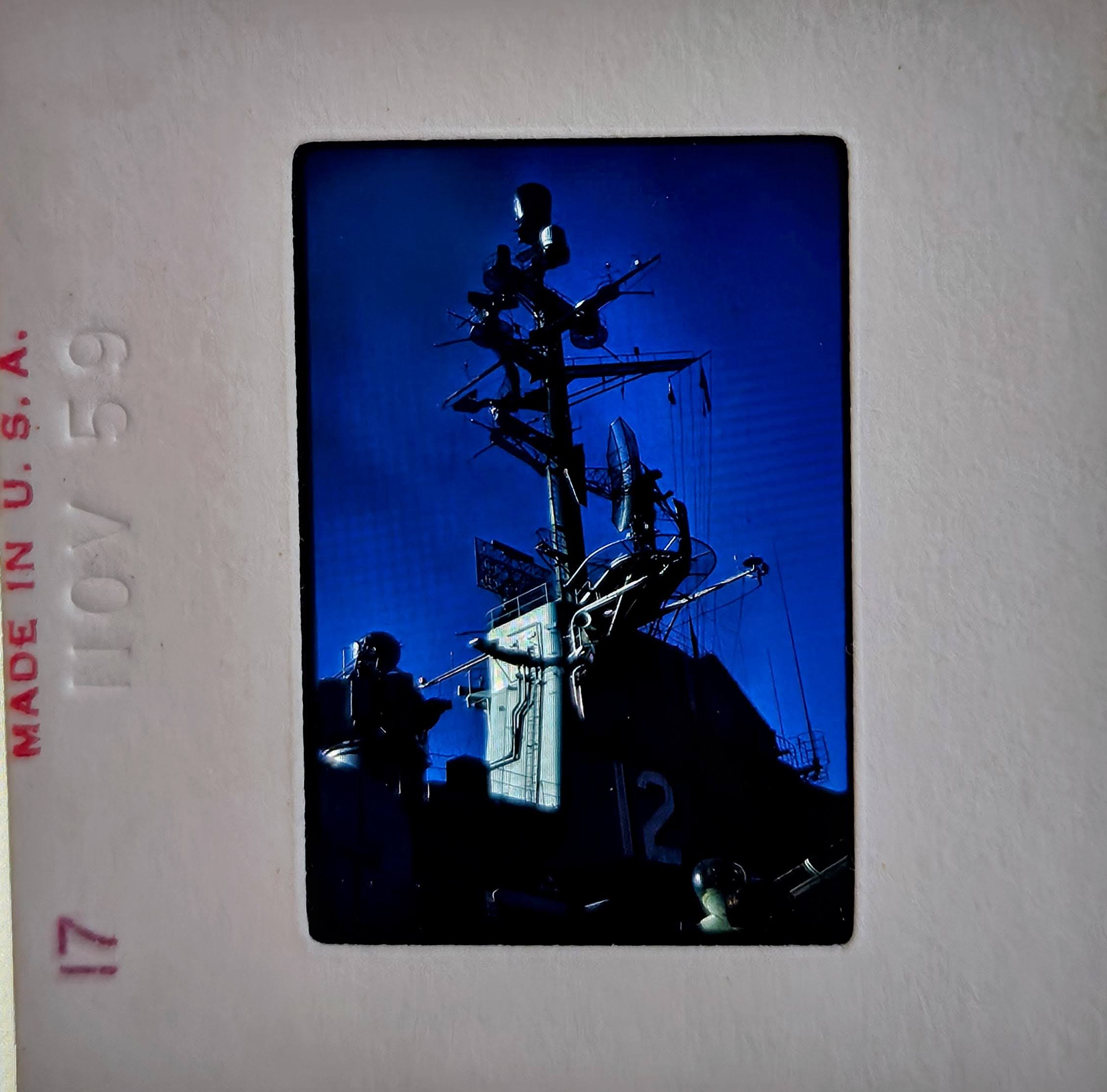
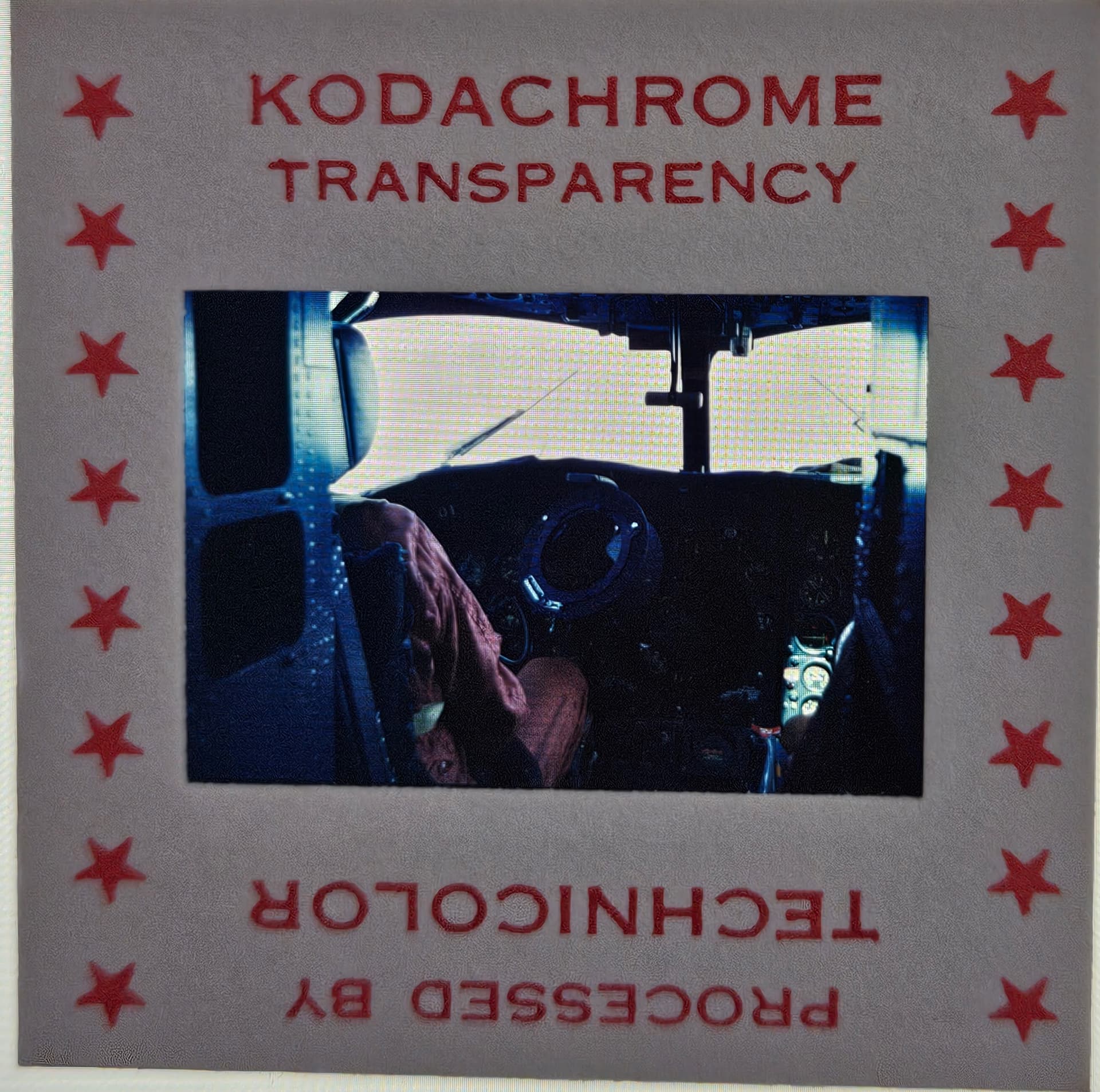
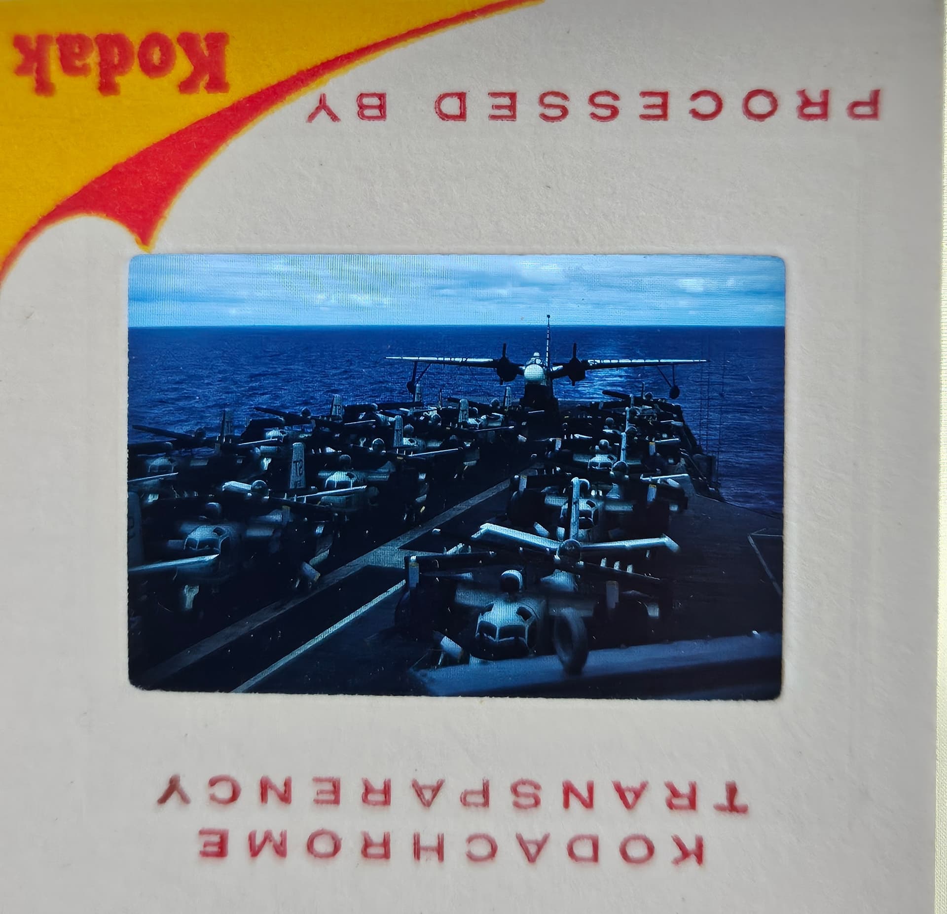
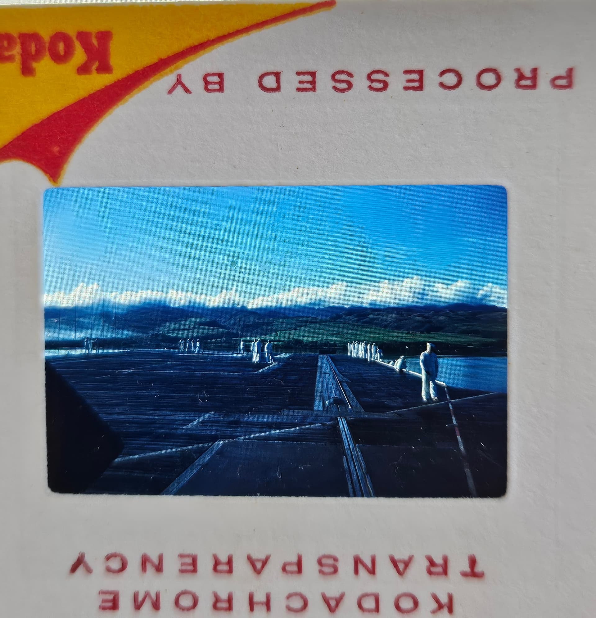
Also, I was cleaning up yesterday and found some old slides in a box. They were dated 1959 and when I held them up to the light, I realized they were photos my dad took on Hornet in 1959! There is an amazing one of the island and mast, some good flight deck ones, and an in-air shot from the S2F. The most unusual shot is looking aft on the flight deck, where there’s a P5M Marlin seaplane at the aft end…I may have to include this in the build!
1 Like