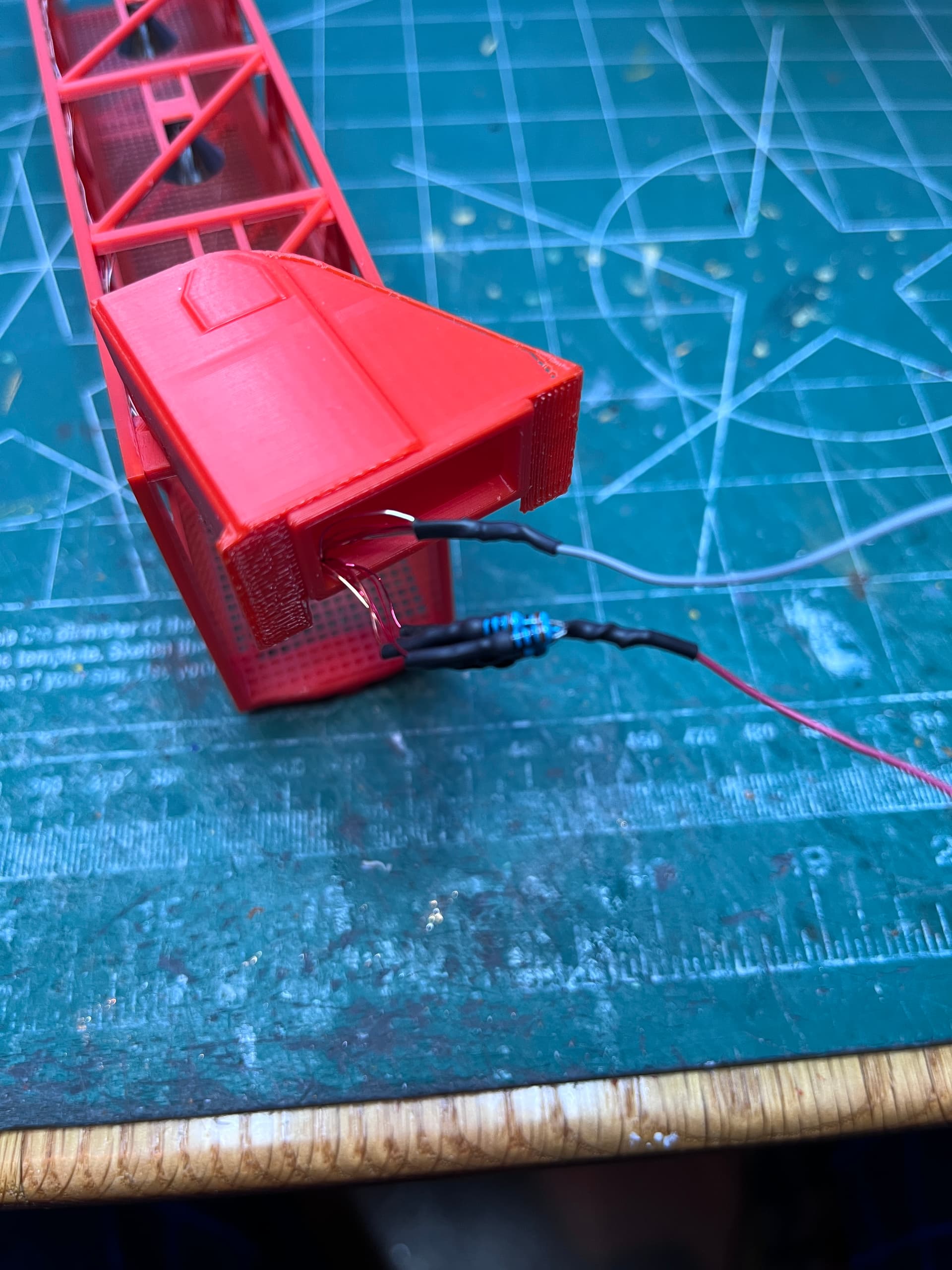
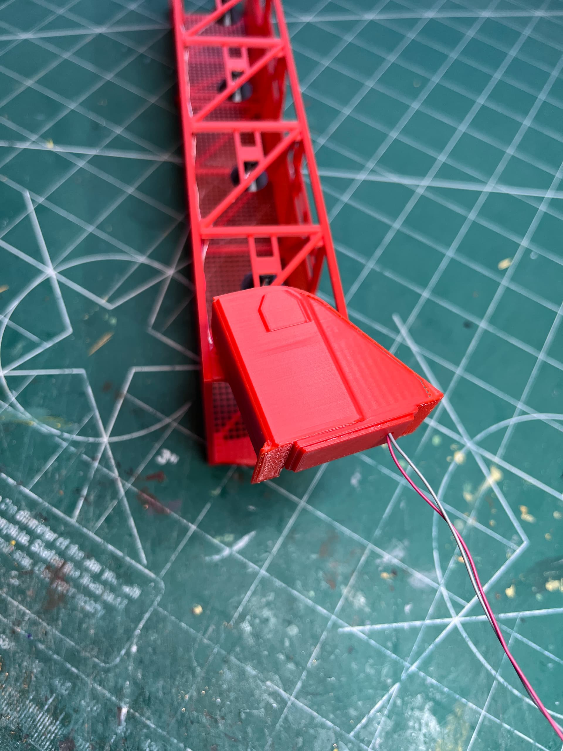
The resistors are soldered on and tested. And here is the completed swing arm upper hinge.
3 Likes
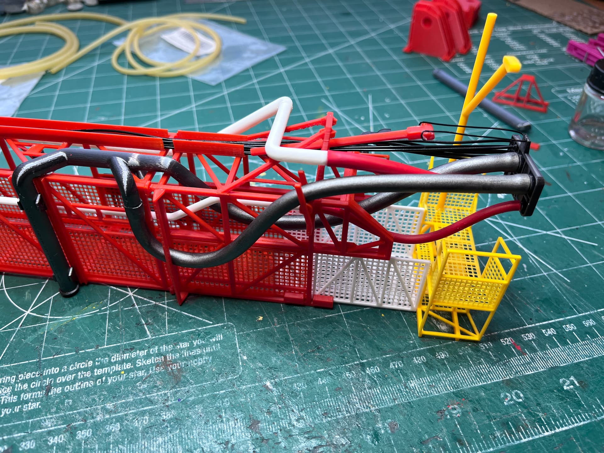
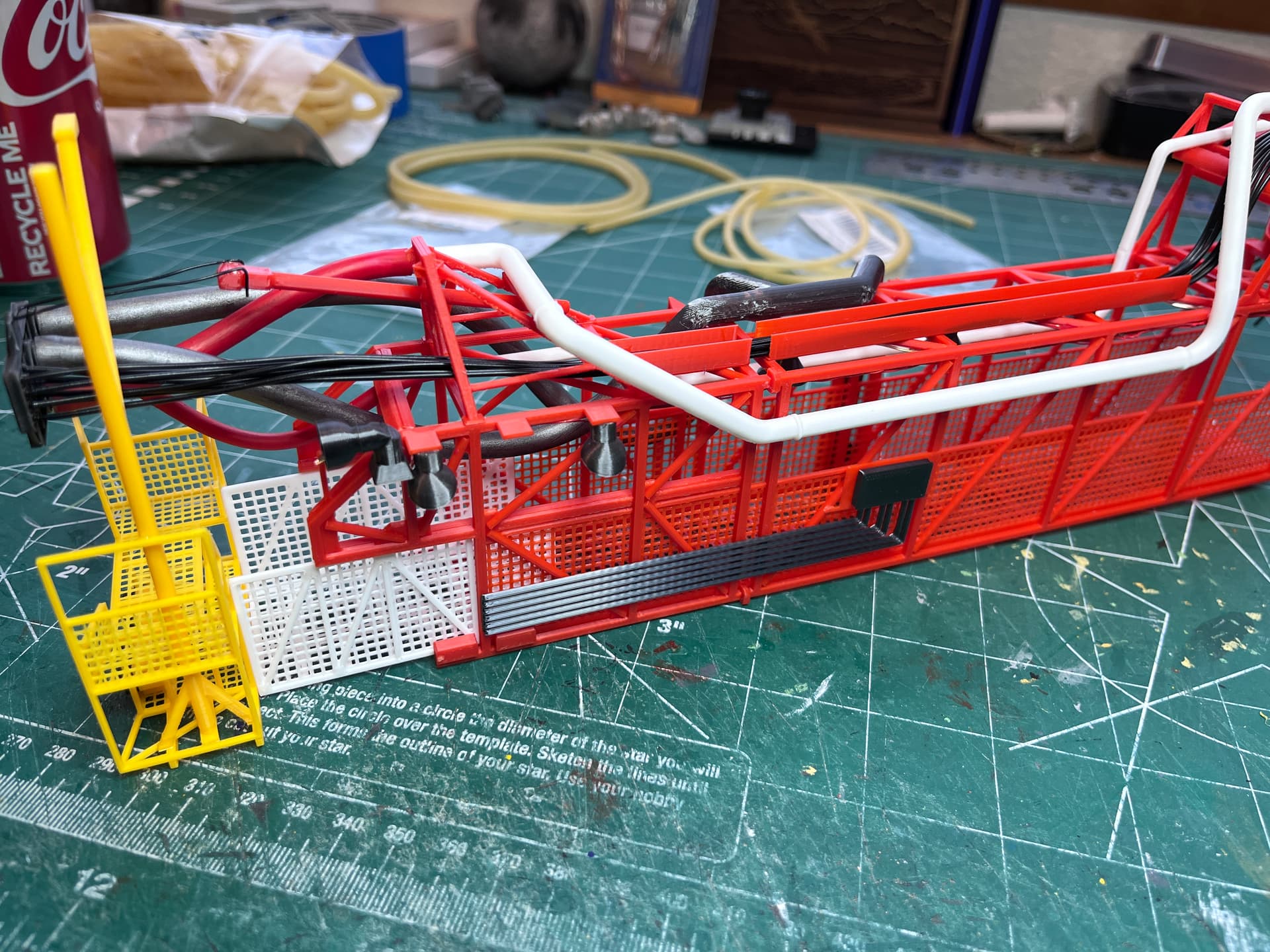
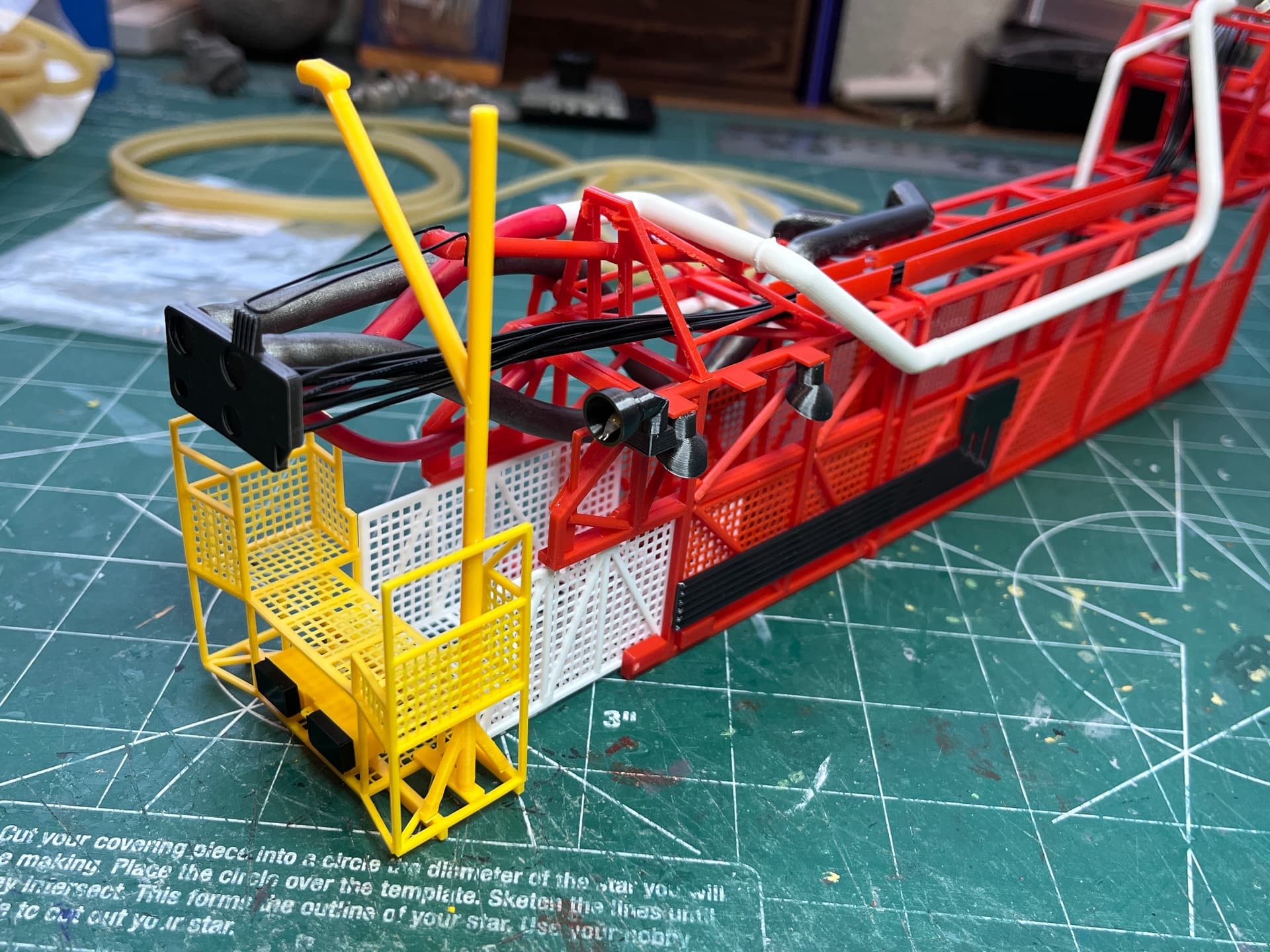
Working the pipes for SA5. Going to use three sizes of latex rubber tubing; 1/4", 1/8" & 1/16". This swing arm has three sizes, the LH2, E4 and a cable pipe. The pipes are sized as close as possible to the correct size. If the pipe is larger than the available tubing, the tubing will be stretched to fit the pipe size and then taper down a bit. Here are the Fusion 360 assemblies of the three pipes. The rubber tubing is not shown. There will also be wire used as well.
2 Likes
Pipes are on, flexible latex tubing is painted and on. The end is almost complete. There are few more small parts to add but for the most part it is complete.
5 Likes
My goodness, where have you gathered all that knowledge? From technical books, or did you work for NASA? It seems you are so well informed that you could even build your own real launch tower and space program. It is amazing what you are doing here. My eyes always pop up in utter disbelief of what I am just seeing and I guess that this is still nothing yet and that much more is about to pop up from every corner, any angle and any little crack in those structures. What are you? An architect, an engineer by profession, a mechanic or what else? I am simply sitting here being flabbergasted by all that.
I have seen many scale reproduction of that launch tower, being them in simple cardboard, polystyrene, resin or even in photo-etched material, but never, and I repeat, never have I seen this kind of accuracy and attention to detail, and I mean, every tiny little one.
When finished this should receive a special prize, not just for the skill in modeling, but also for your dedication and commitment to such a great documentative and historic recreation of something that many years ago represented a pivotal moment in human lives all over the world.
I don’t know what to add to this anymore, but will religiously continue to be stupefied by your very ingenuous and highly original creation.
Man, how I wished I had your skills and your know-how… but above all, your patience.
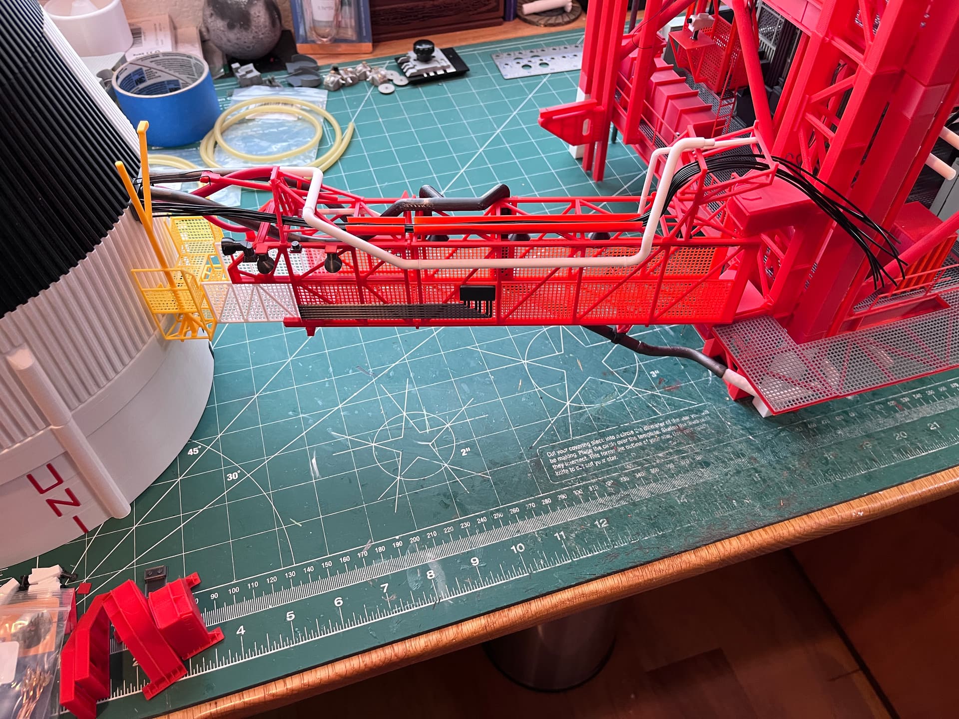
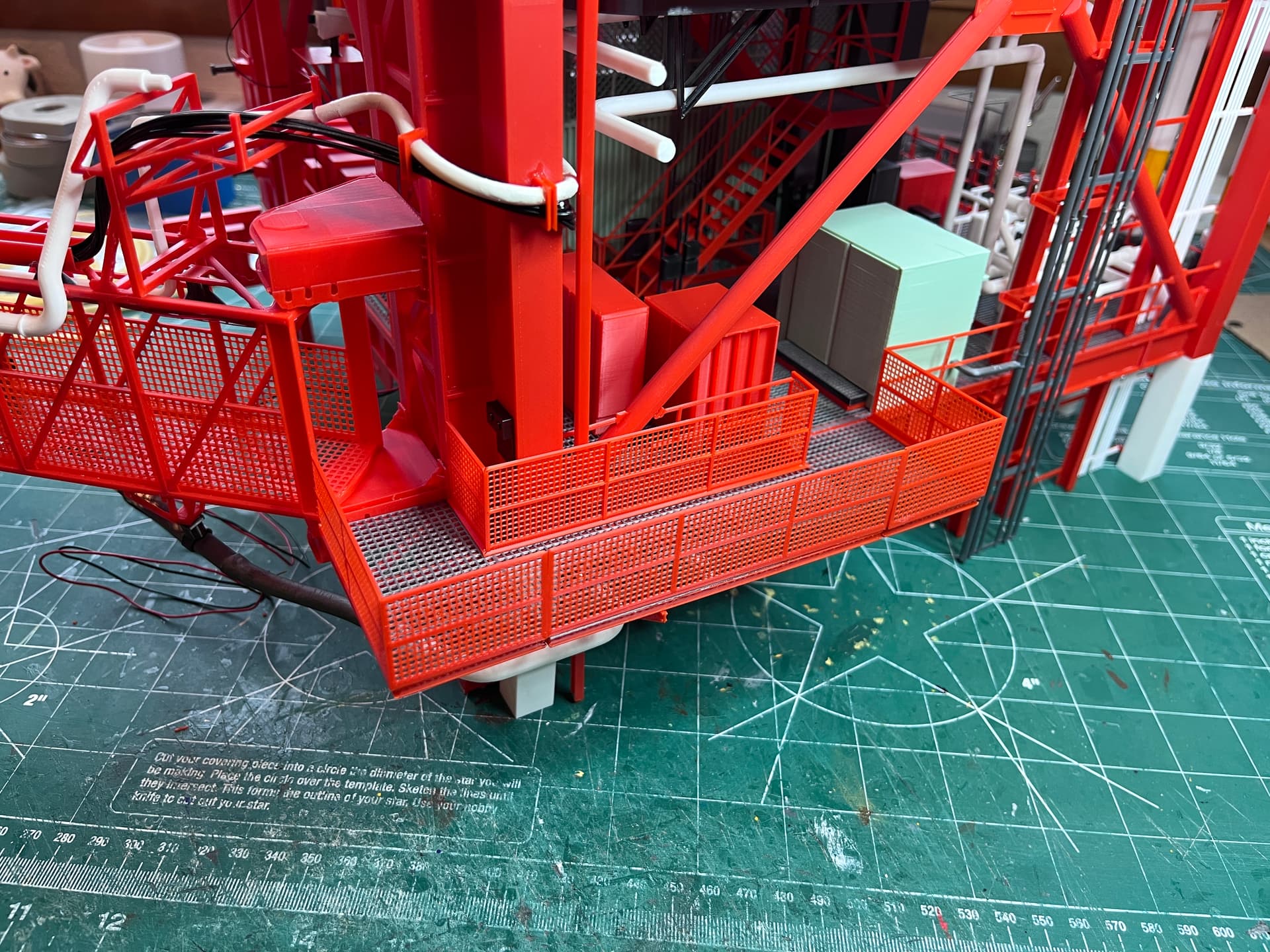
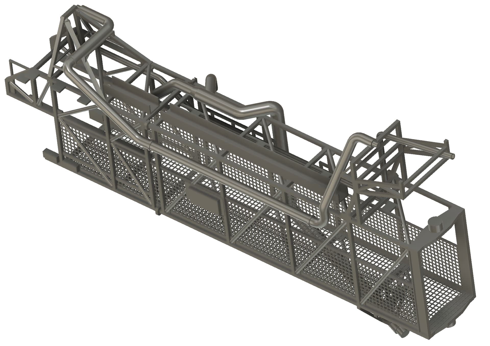
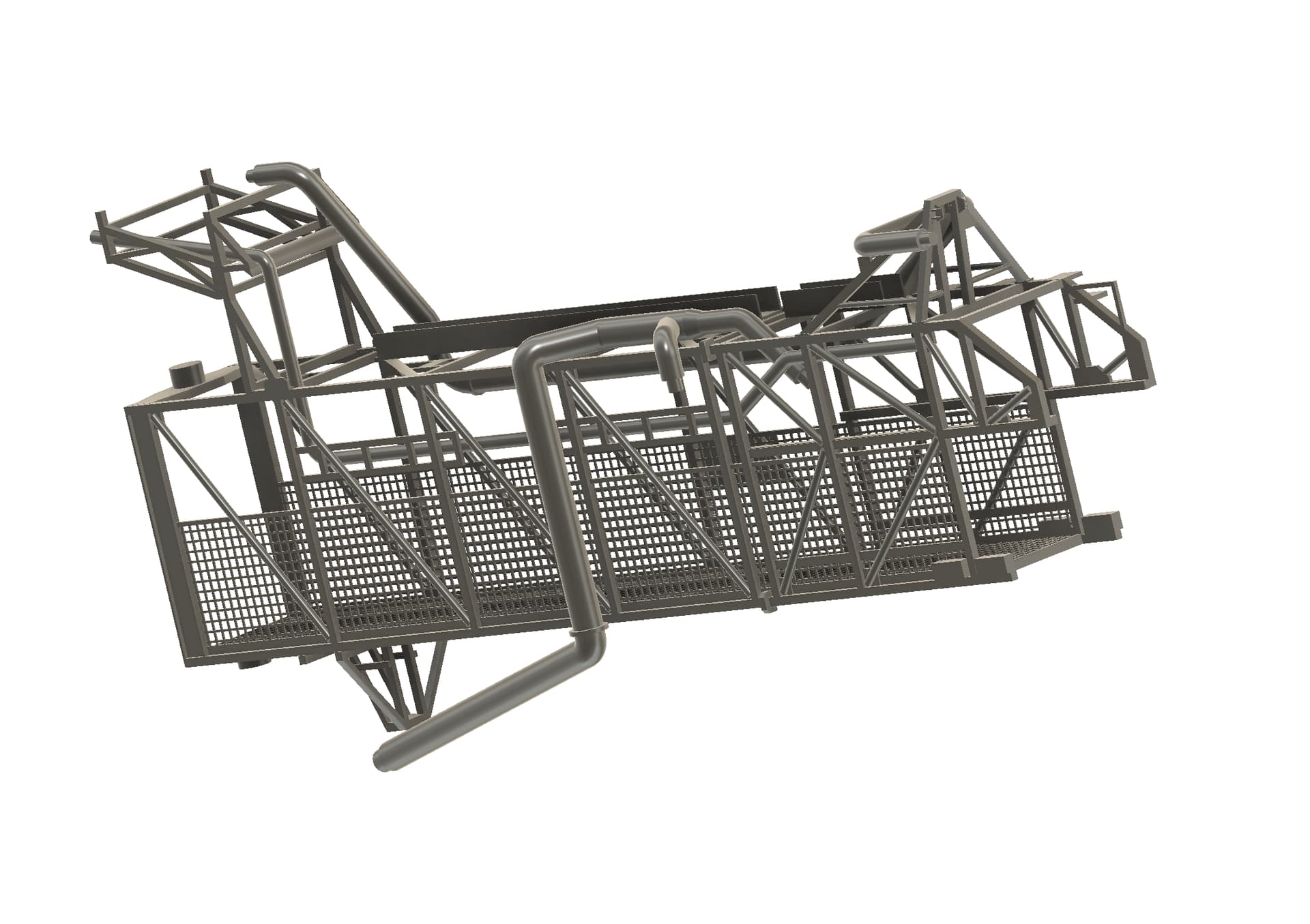
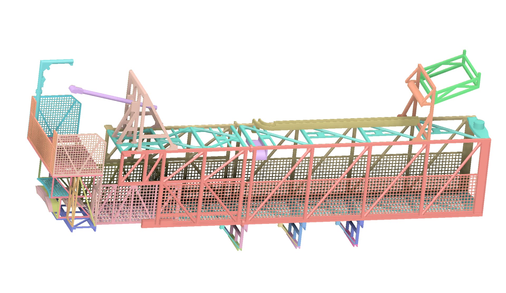
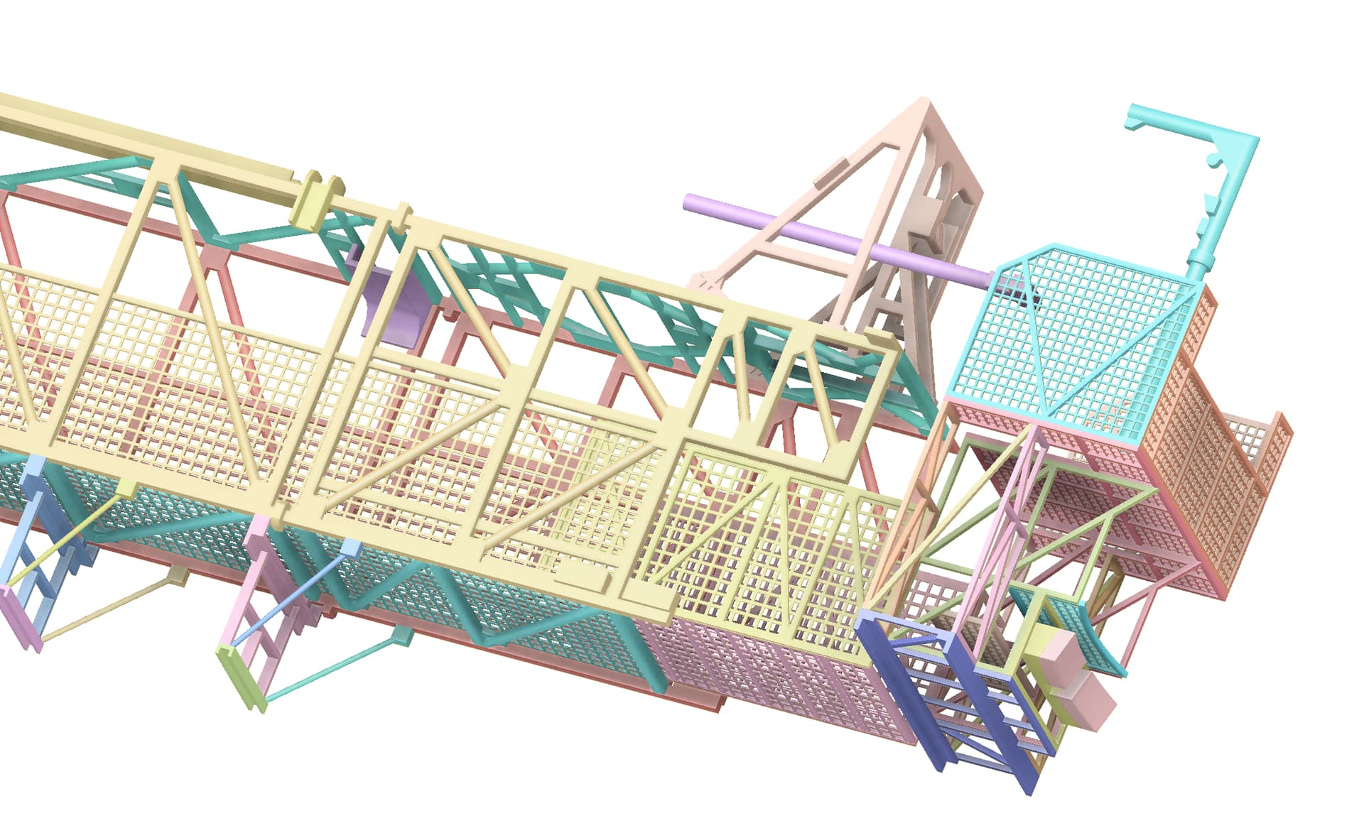
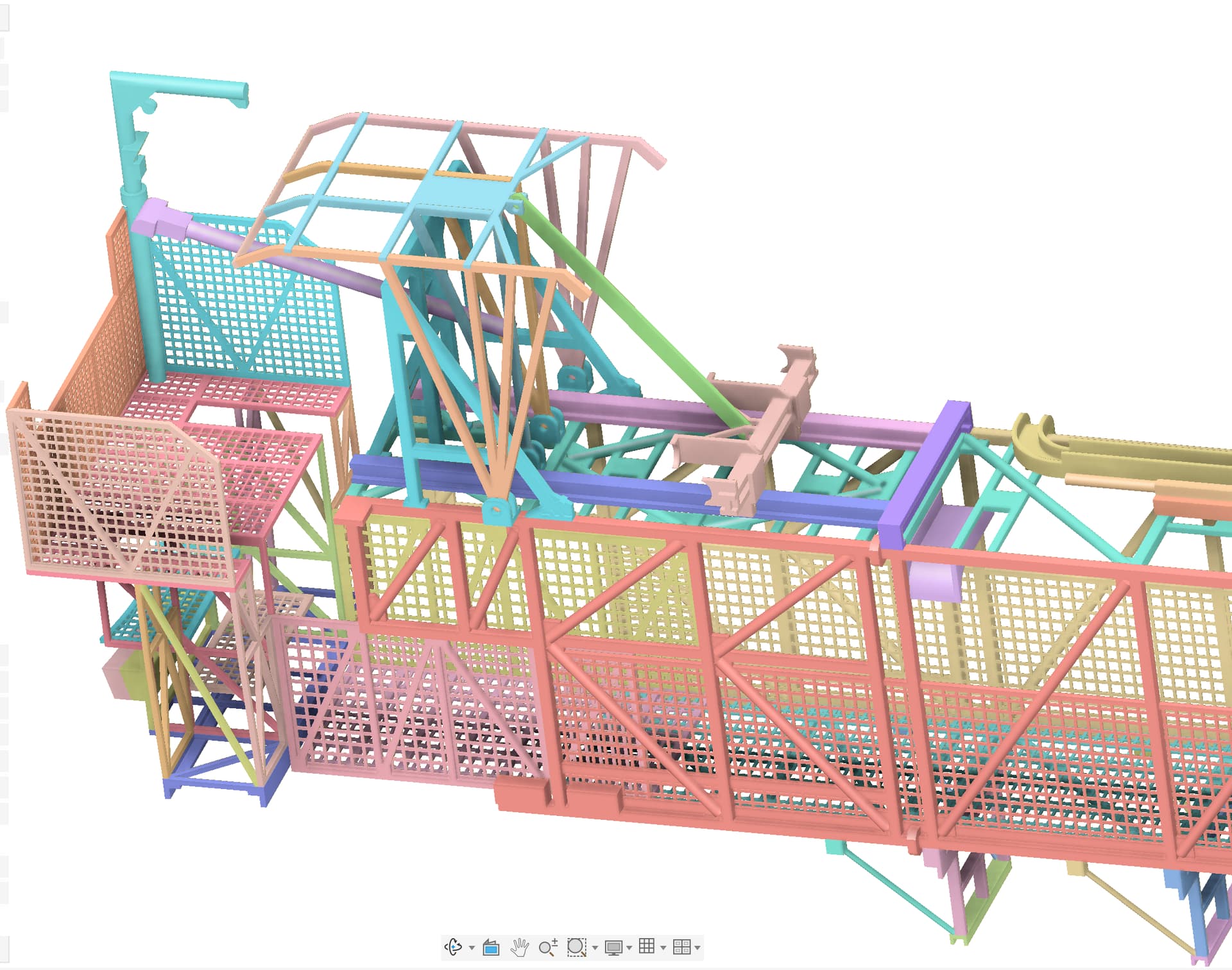
Been working on Swing Arm 6. Most of the arms share the same main section (first and second elements) that extends out towards the rocket. The business end of each arm is very different, both the cage structures that extend out to meet the rocket and the interface retract mechanisms. The whole purpose of this model is to make the swing arms functional. This arm’s retract mechanism is going to be a challenge. Most of the arm parts are designed except for the retract mechanism. Here is an assembly of the parts designed so far from two different angles. It consists of 44 parts so far.
1 Like
The retract mechanism initial design is complete. Now I need to start printing parts and designing the pipes and where the flexible parts will go so the retract mechanism will function.
2 Likes
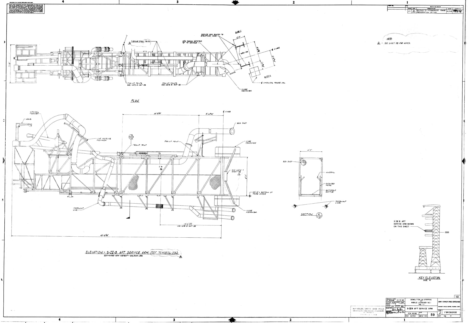
Before starting the print process I remembered there are other diagrams of the swing arms created by the company that was demolishing the LUTs. Actually part of the LUT towers were reused for the shuttle launch complexes. These diagrams are out on the LUT Group site thanks to Tim Maw. When checking the lengths versus my parts I realized I was about 15mm short for SA6. This is because SA6 attaches towards the top of the third stage where the rocket is narrowing down.
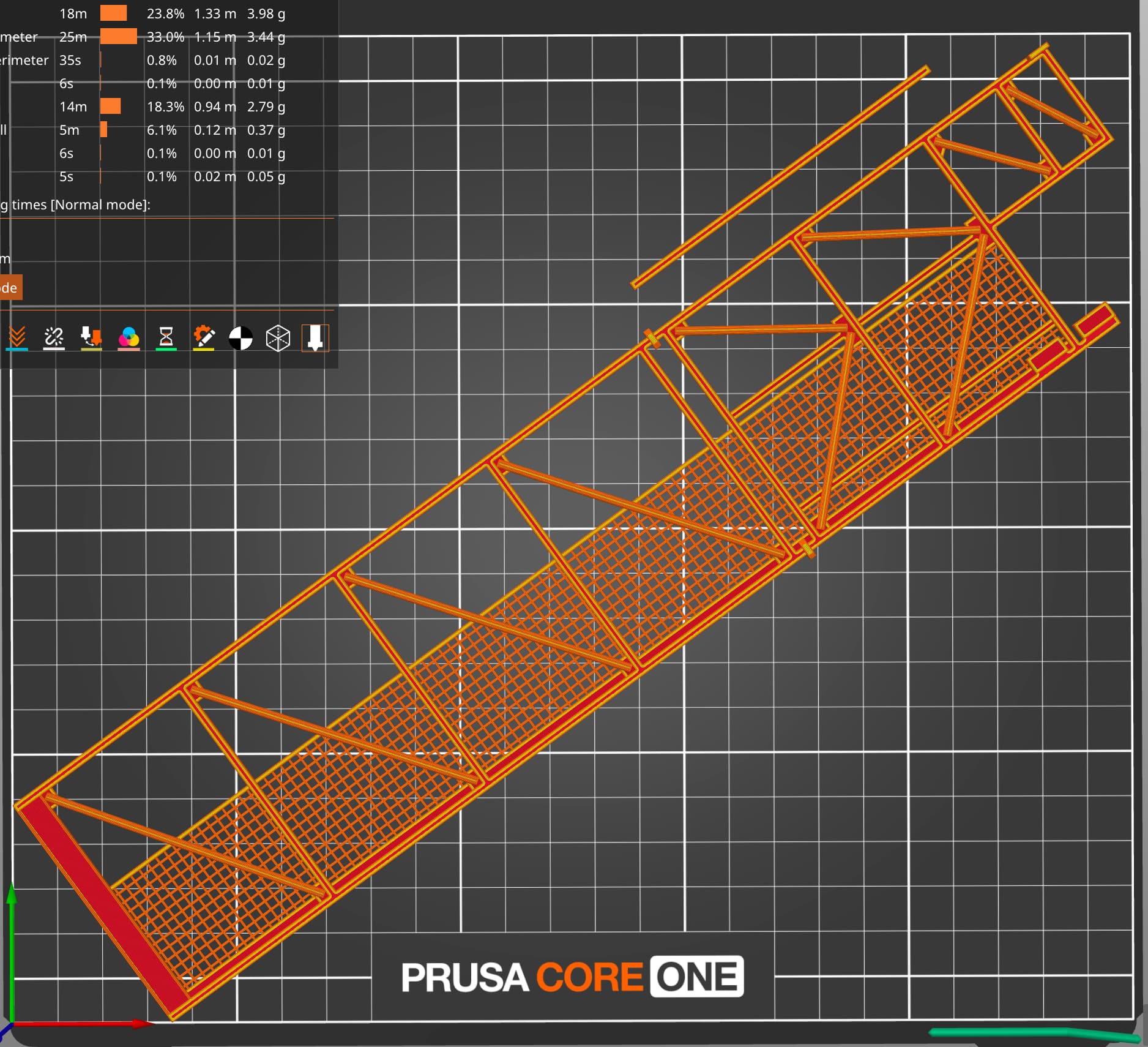
After extending the second element I am ready to print. These sides were just barely able to fit on the print plate. This also tells me when I get to SA7 a complete side will not fit and I will have to section up those parts, probably between the first and second elements.
2 Likes
Had to realign the SA5 small top pipe. These don’t work unless they are aligned with the center pivot point.

2 Likes
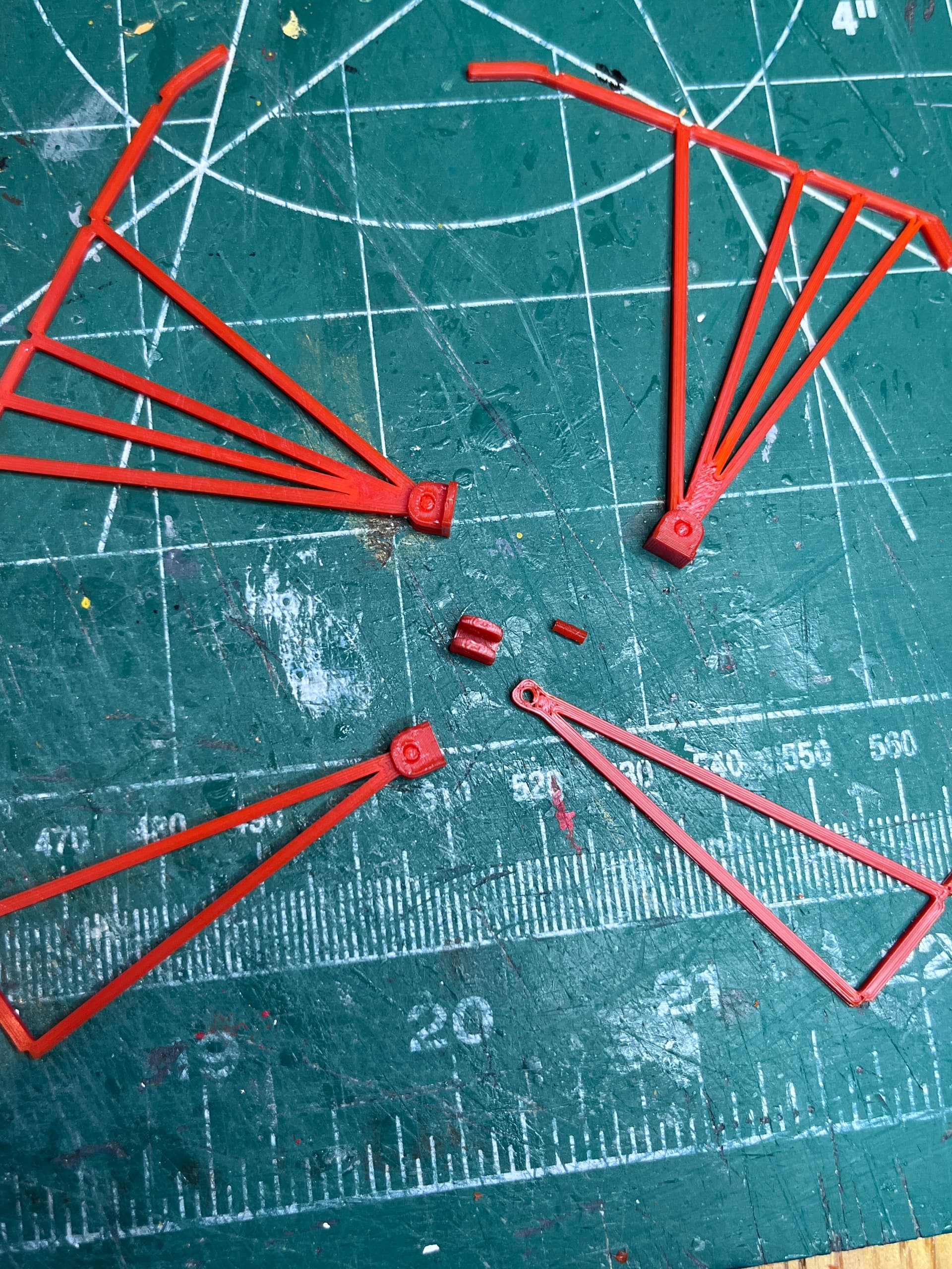
The SA6 retractable fueling mechanism is complete. This is the reason I wanted to make a portion of the tower at a larger scale, so I could get the detail in these mechanisms and get them to function. The movable part is attached with four hinges. The pins are small but they fit tight without glue.
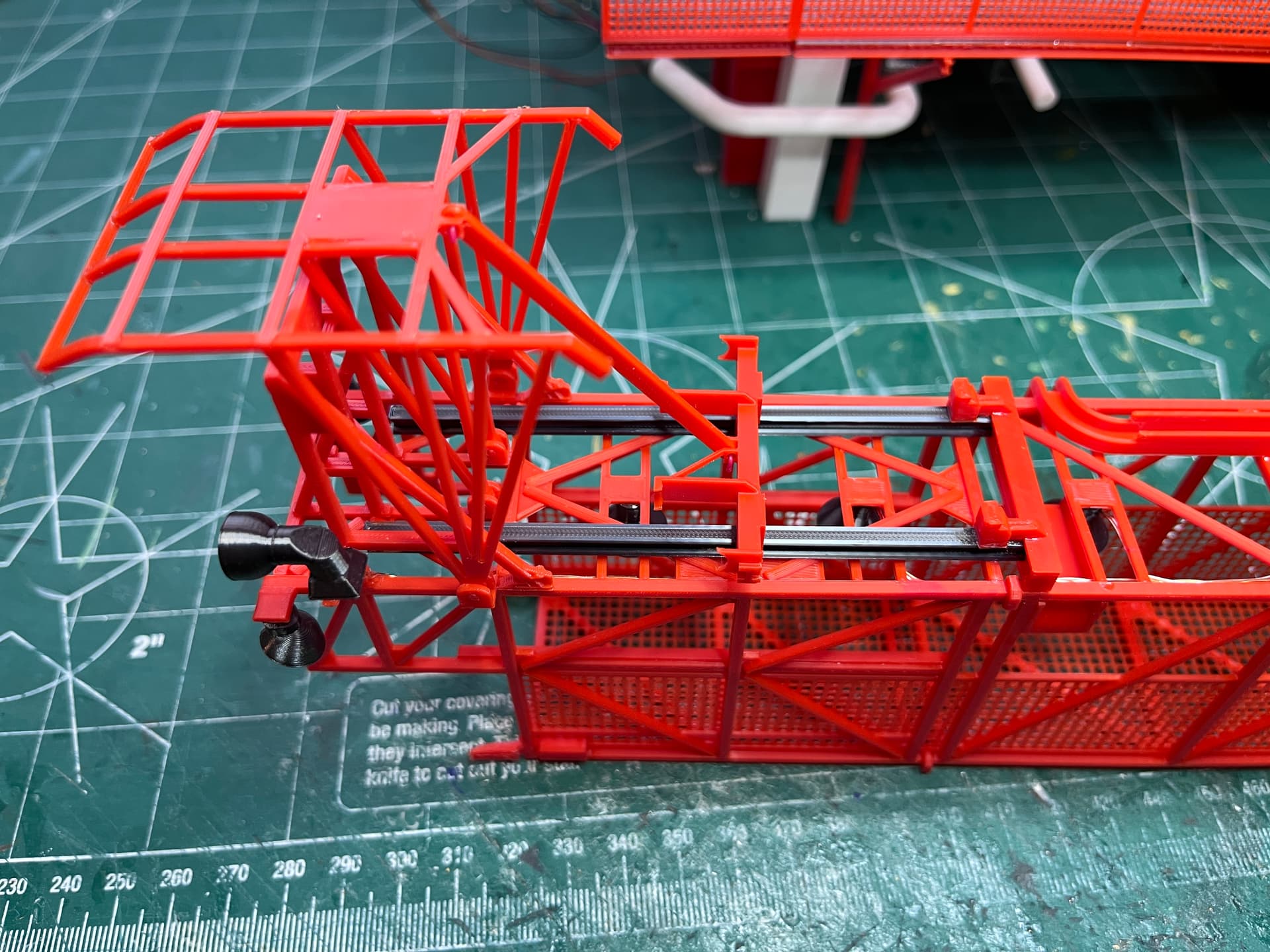
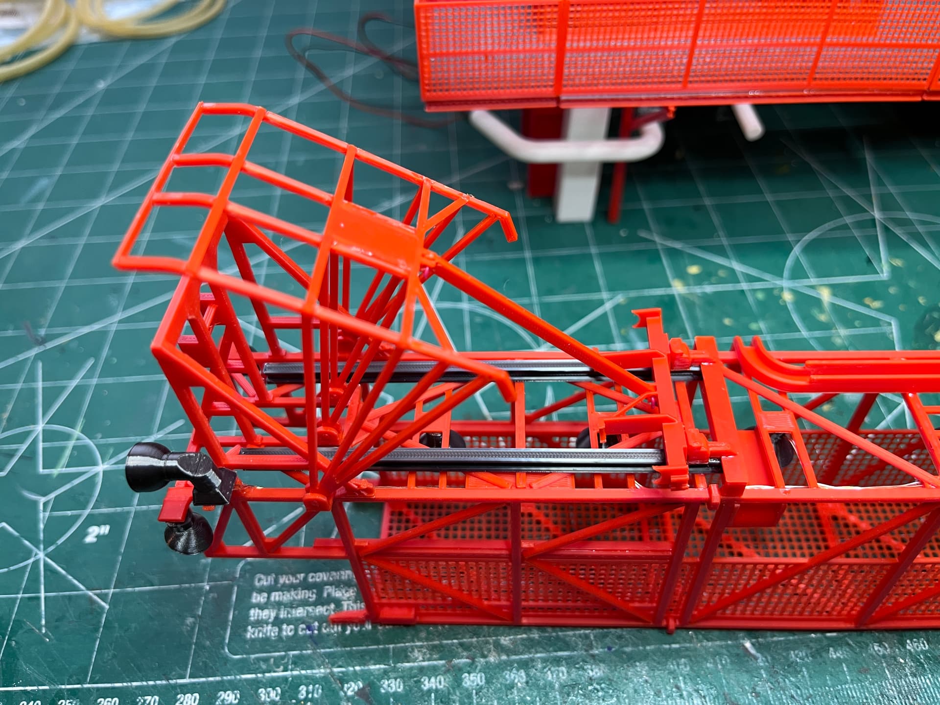
4 Likes
The amount of detail is remarkable. Only ship builders come close with the rigging! Seeing this makes me wish I had a good 3D printer.
Gary
Thanks. I am pushing the FDM printer to its limits. For really fine detail I use a resin printer but the colors are so limited.
Here are the next parts I’m working on, the large pipes; LOX, LH2 and E3. Getting everything lined up before printing parts. I may have to add some rail sliders on the other ends of the LOX & LH2 pipes to keep them from lifting up when the flexible hoses are added.

2 Likes
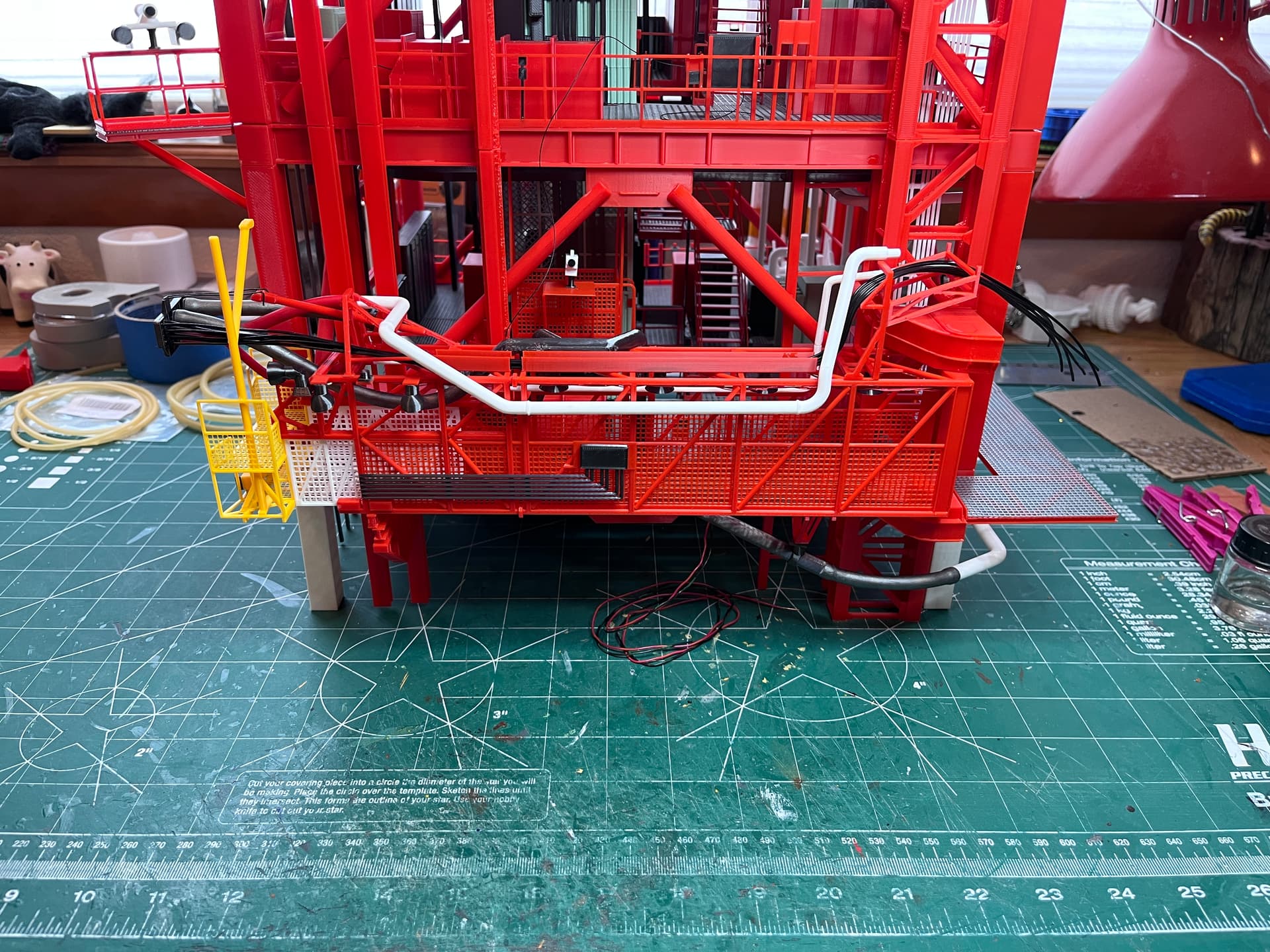
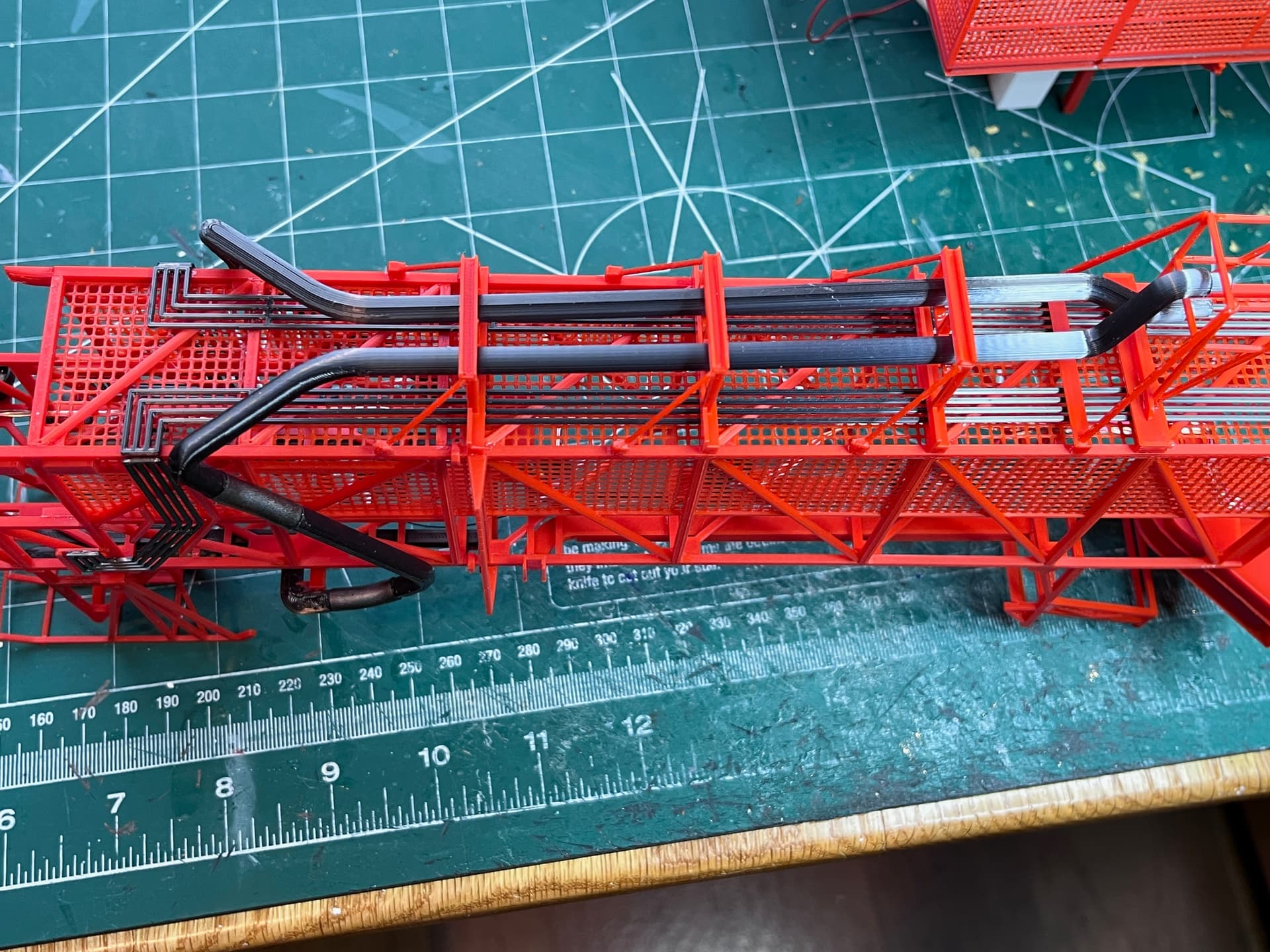
The LOX/LH2 pipes are in place. Before that there are other pipes underneath that were added. The pipes start underneath, go up the sides and end up on top. They slide along with the retract mechanism, parallel to the rails. To make them more stable I added a pair of front rail guides that are gray. You can see them when the mechanism is retracted. Here are pictures of the left side with the mechanism extended and then retracted. To keep it retracted I wedged a pair of tweezers in. It is not completely retracted in this picture.
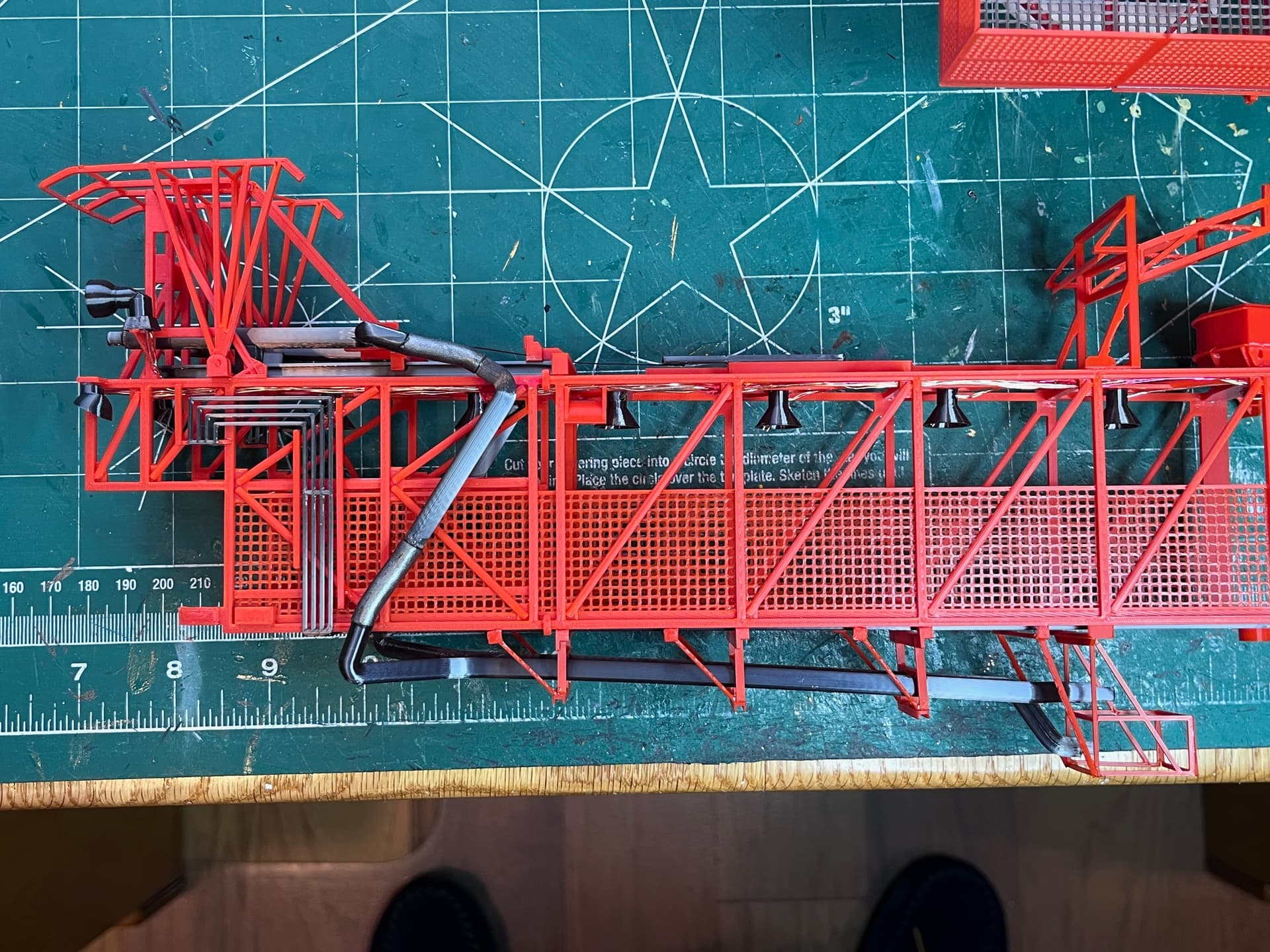
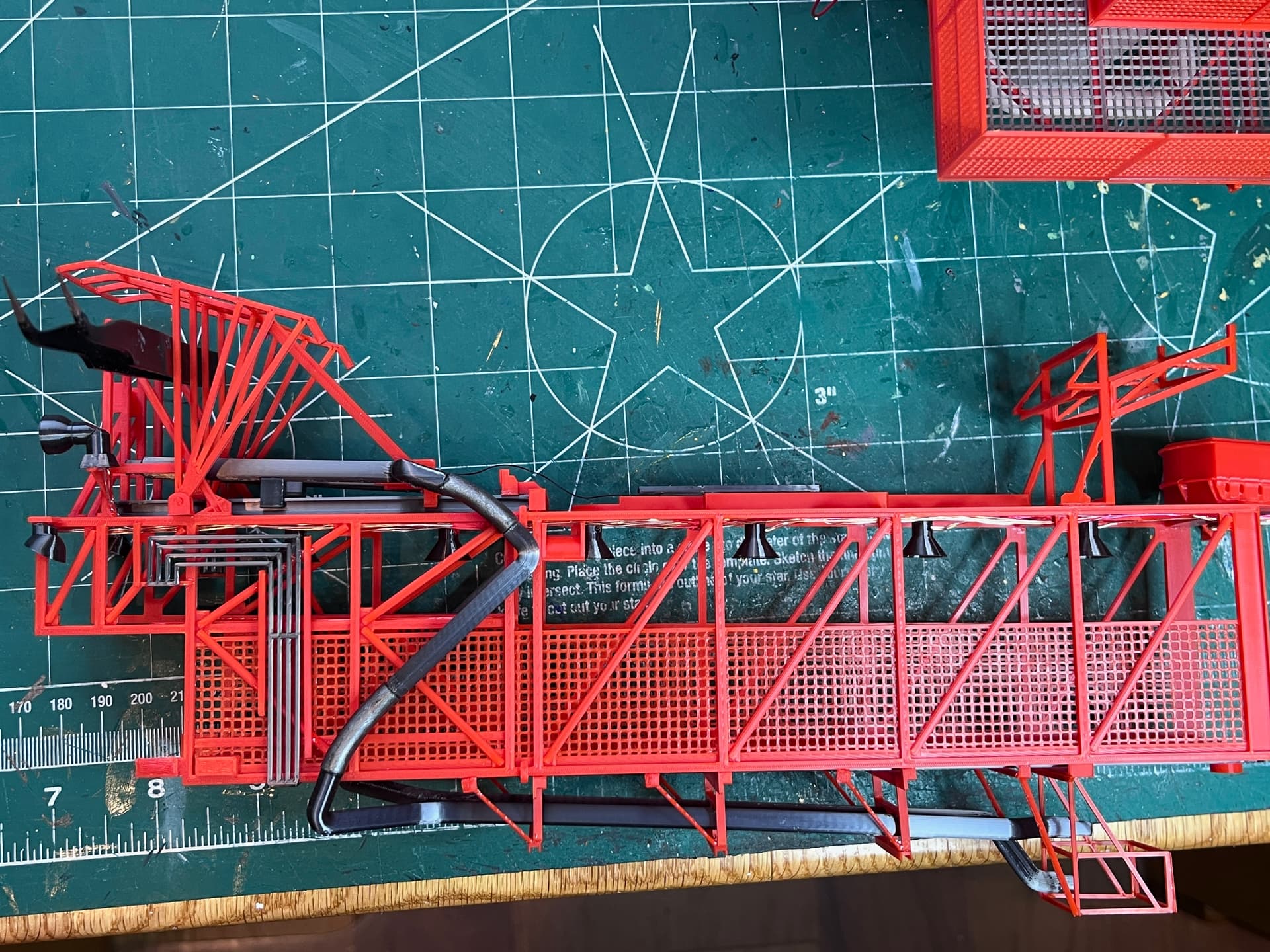
Here is a picture of the pipes from the bottom. Next up I need to add the environmental pipe which runs along the top, inside the walkway before moving to the outside.
3 Likes
To design these parts I am following the work of others, both the MicroArtwork and the work on TurboSquid. They agree for the most part. For the SA6 umbilical connector, the connector plate was not jiving with the Saturn V model I am using. This is the only connector that does not agree so I did some research. Here is the printed model.
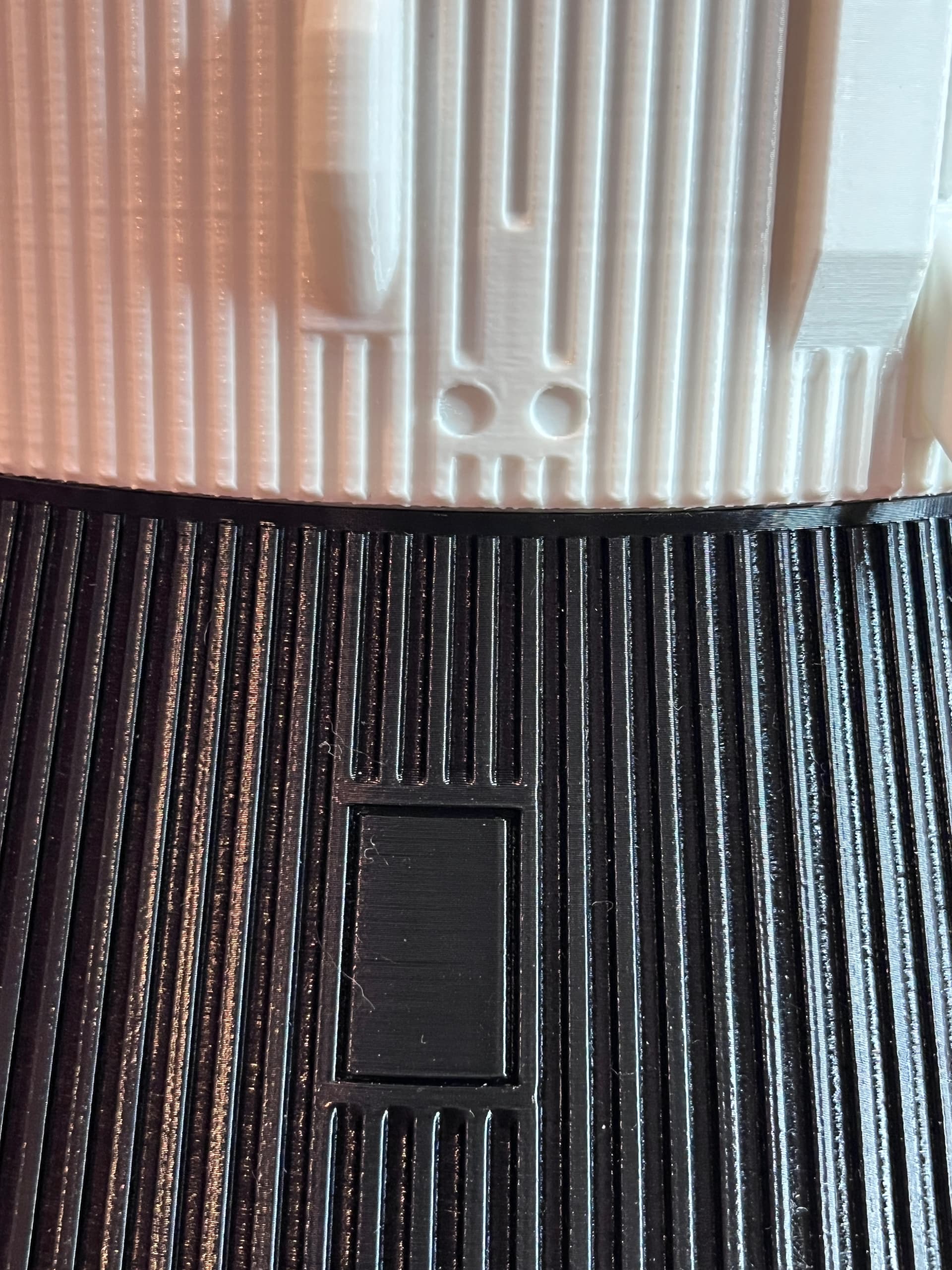
The two lower connectors seem too close together. Here is a drawing of the connector plate I found in a NASA document. It shows separation between the two lower connectors and all the electrical and pneumatic lines between them.
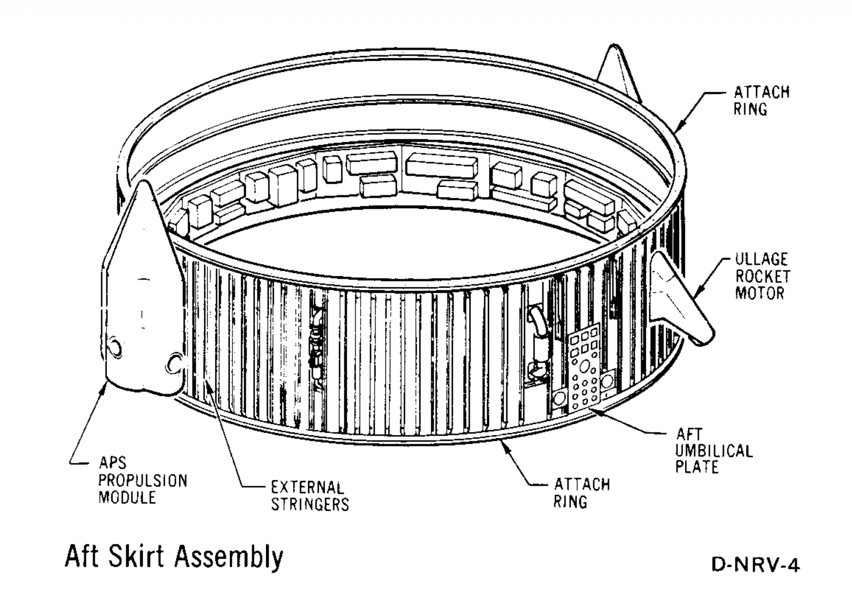
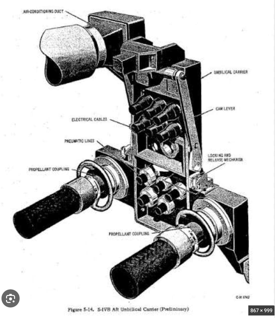
This agrees with the umbilical connector plate. I am not going to go back and reprint the Saturn V model. Most people won’t notice this error, but I am trying to be as accurate as possible.
3 Likes
Your attention to detail is astounding!
The business end of SA6 is complete. With the walkway held in place, here it is with the umbilical extended along with the working platform.
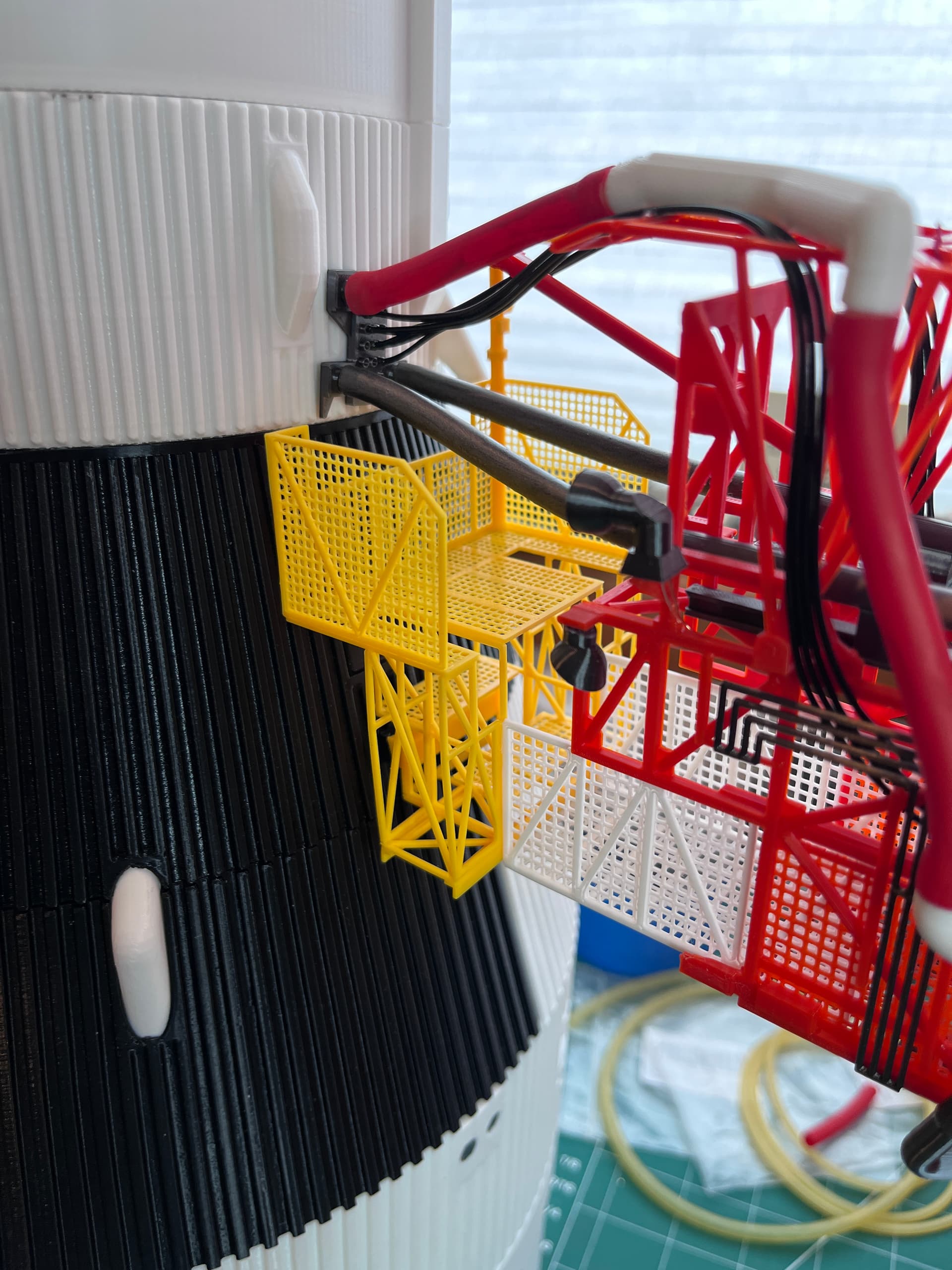
And here it is with the platform retracted.

The umbilical wants to stay extended. Here it is off model with the umbilical retracted, being held in place with a clothes pin.

2 Likes
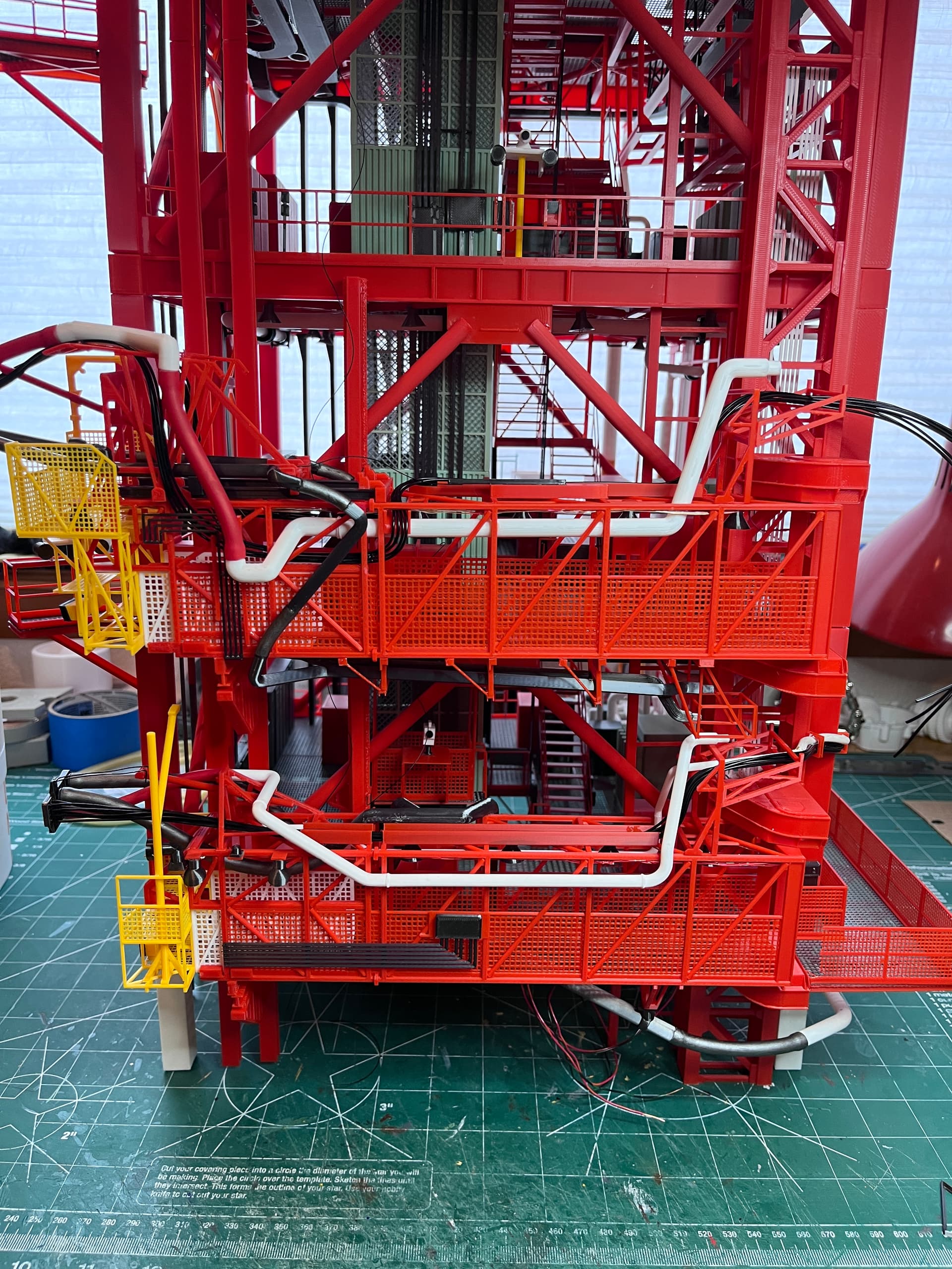
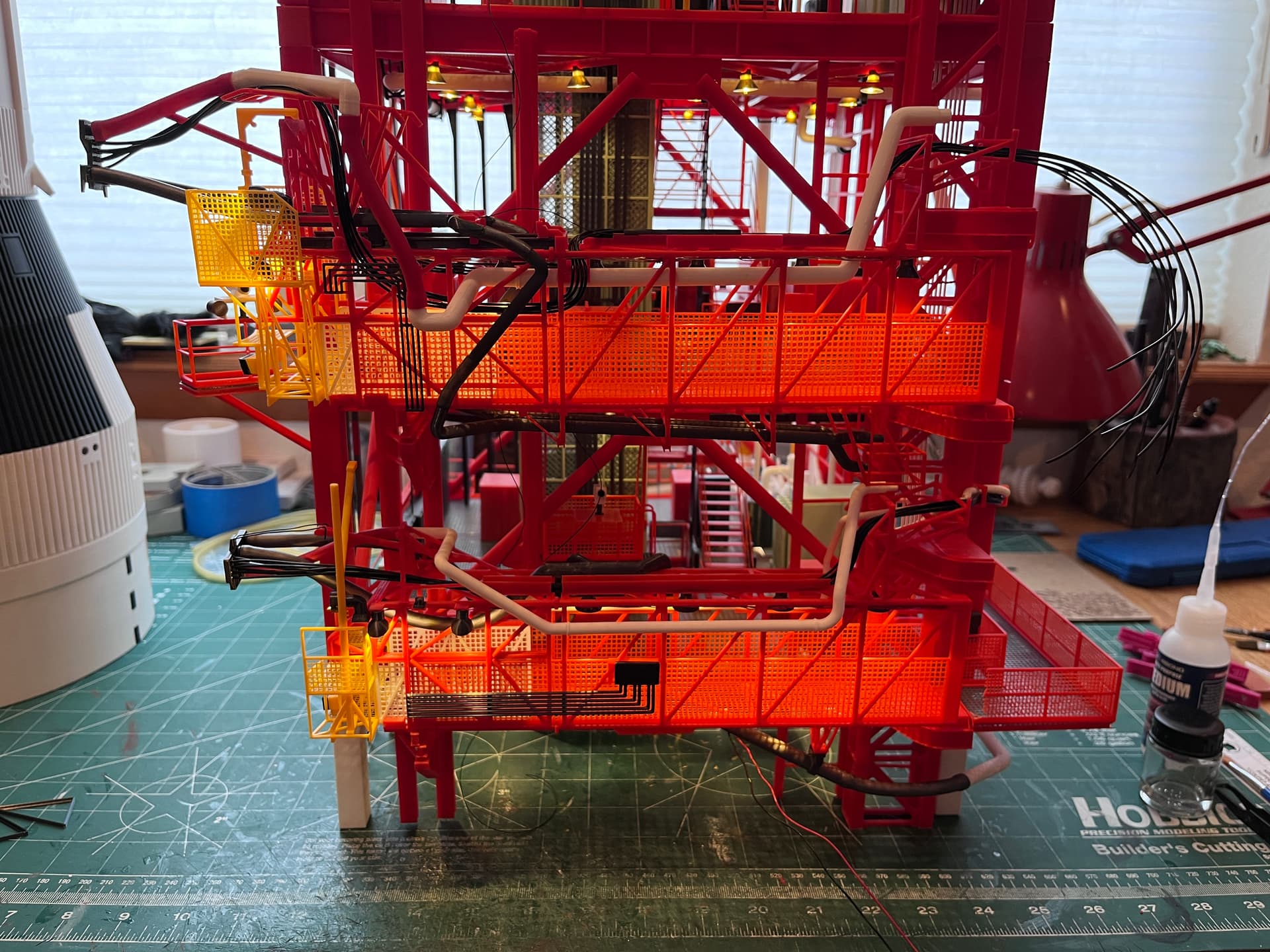
Love It! Love It! Love It!
Haven’t checked in on this in a bit. It’s looking amazing. Cool to see it plumbed to the ship.
1 Like