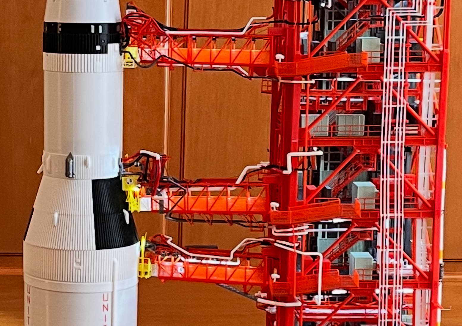
When modeling the Apollo LUT I was frustrated in trying to get enough detail in the swing arms at a scale of 1/60. Scale is the enemy of detail. At a scale of 1/60 the LUT model is over 7 feet tall. I knew I wanted to go back and model at least one of the swing arms at a larger scale to show the detail in these important parts. What modelers do, say with wooden ships, is to model a cross section at a larger scale so you can see more detail. This got me thinking. What if I sliced the LUT, not vertical, but horizontal to include a swing arm or two?
I’m thinking a cross section that includes two or three floors, one or two swing arms and include a cross section of the Saturn V. But what section is the most interesting? Most people would gravitate towards a section that includes the capsule and swing arm #9. To completely model that arm you would need to include swing arm #8 since it is so close below and the DRRS arm. You would need to go up to level 360 to include the cables and supports for swing arm #9 and the DRRS. Swing arm #8 and #9 are probably the least interesting as is the equipment on those levels. This is not what I am looking to model.
Another candidate might be swing arms #2, #3 and #4. They are very interesting swing arms. You could slice from level 110 through 170. The downside I see is at these levels the slice of the Saturn V is not very interesting.
A third candidate would include swing arms #5, #6 and #7. This section would include three very interesting swing arms, very jam packed floor levels and would include the entire third stage of the Saturn V. It would also be interesting to slice the Saturn V in half horizontally so you can see the engines and tank internals. This would include levels 190 through 270.
I believe the third candidate is the way to go. But at what scale? This cross section at the current 1/60 scale would produce a model that is 12” (305mm) x 21” (533mm) x 17” (432mm) tall. If I go with a scale of 1/30 (twice as big) that would produce a model that is 24” x 42” x 34” tall. I usually say go big or go home. This model should be sized to be a table top model. A 1/40 scale (1.5x larger) would produce a model that is 18” x 31.5” x 25.5” tall. This is a good balance of showing more detail and being a table top model.
Most of the required parts are already created. This model would simply involve scaling up existing part and slicing the Saturn V parts in half. Here is an overview of the major changed. Most new parts would be concentrated in the swing arms and elevator shaft, making them higher fidelity and more accurate along with adding other doo-dads that were too small to add before.
The swing arms should fully retract.
The swing arm retract mechanisms at the Saturn V end should be functional.
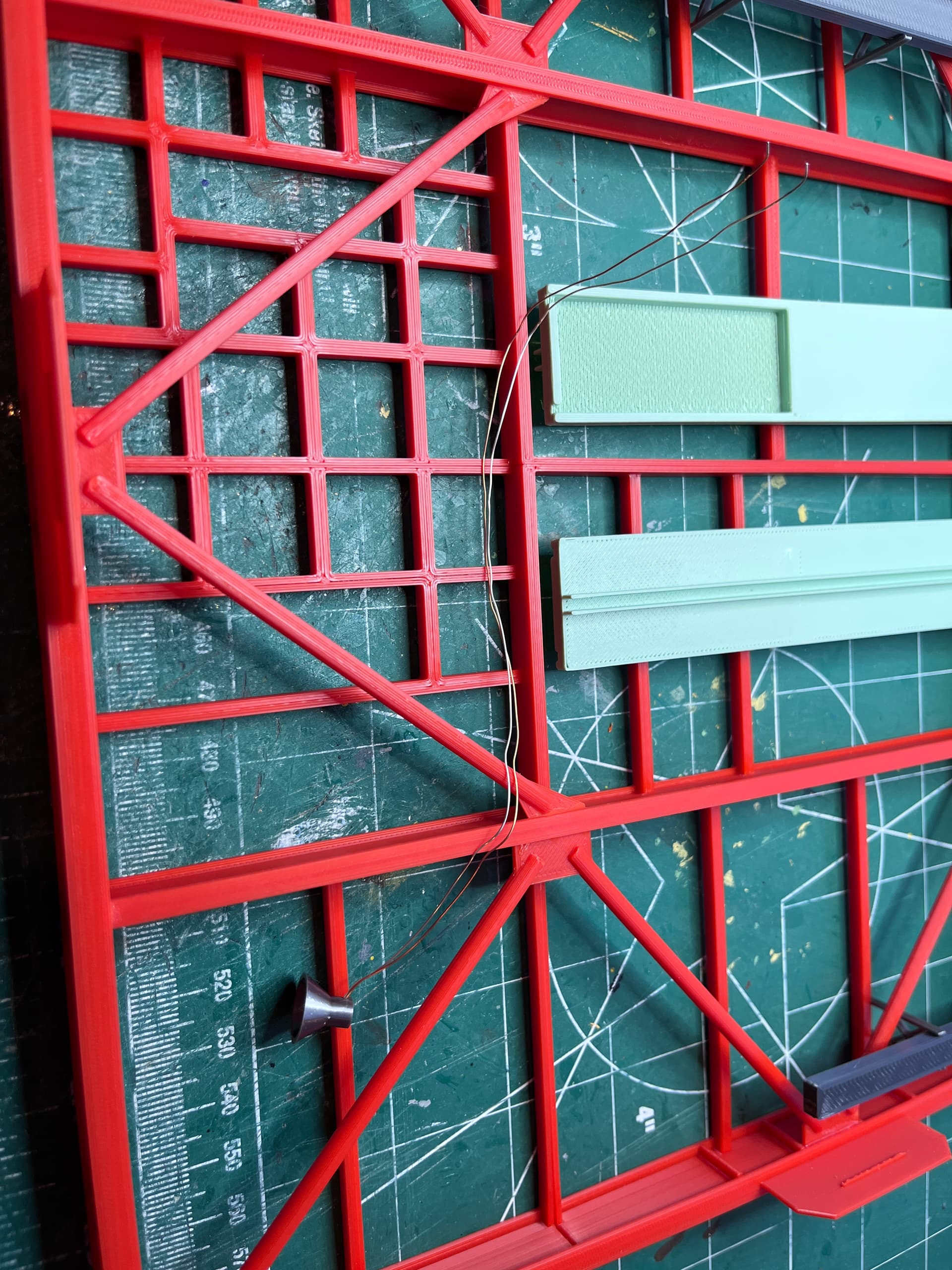
The model should be lit. This requires a remake of the light hoods.
Only two wires are required and can be run up one of the 12” braces, the ones near the swing arms. This part is already created at the top level.
Make the elevator interior accurate and include the elevator cars.
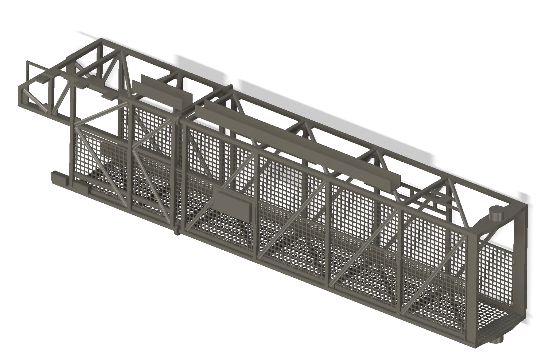
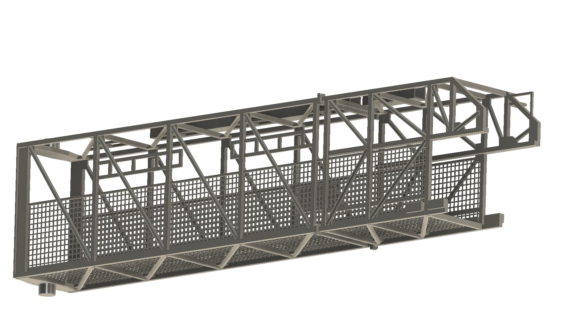
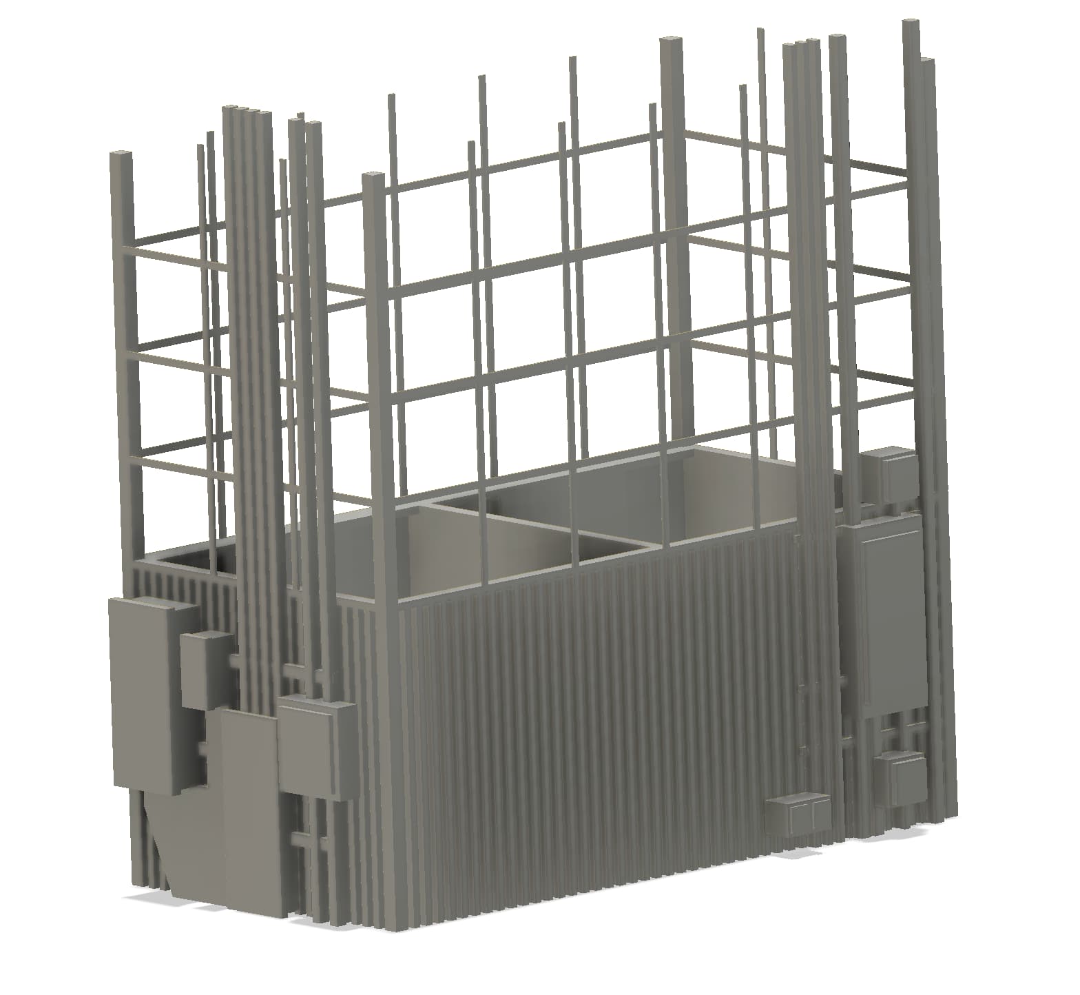
Make upper portion of elevator cage more accurate.
Floor grating to be finer, using 0.25mm nozzle.
Rework support and locking columns since there will be no removable sections.
The model needs to be firmly attached to a wooden base, probably a 3/4” or 1/2” piece of plywood. The light wires need to go through this base to a box that contains a switch and a power connector. This box should contain a label. The label should say something like “Apollo LUT - Cross section”.
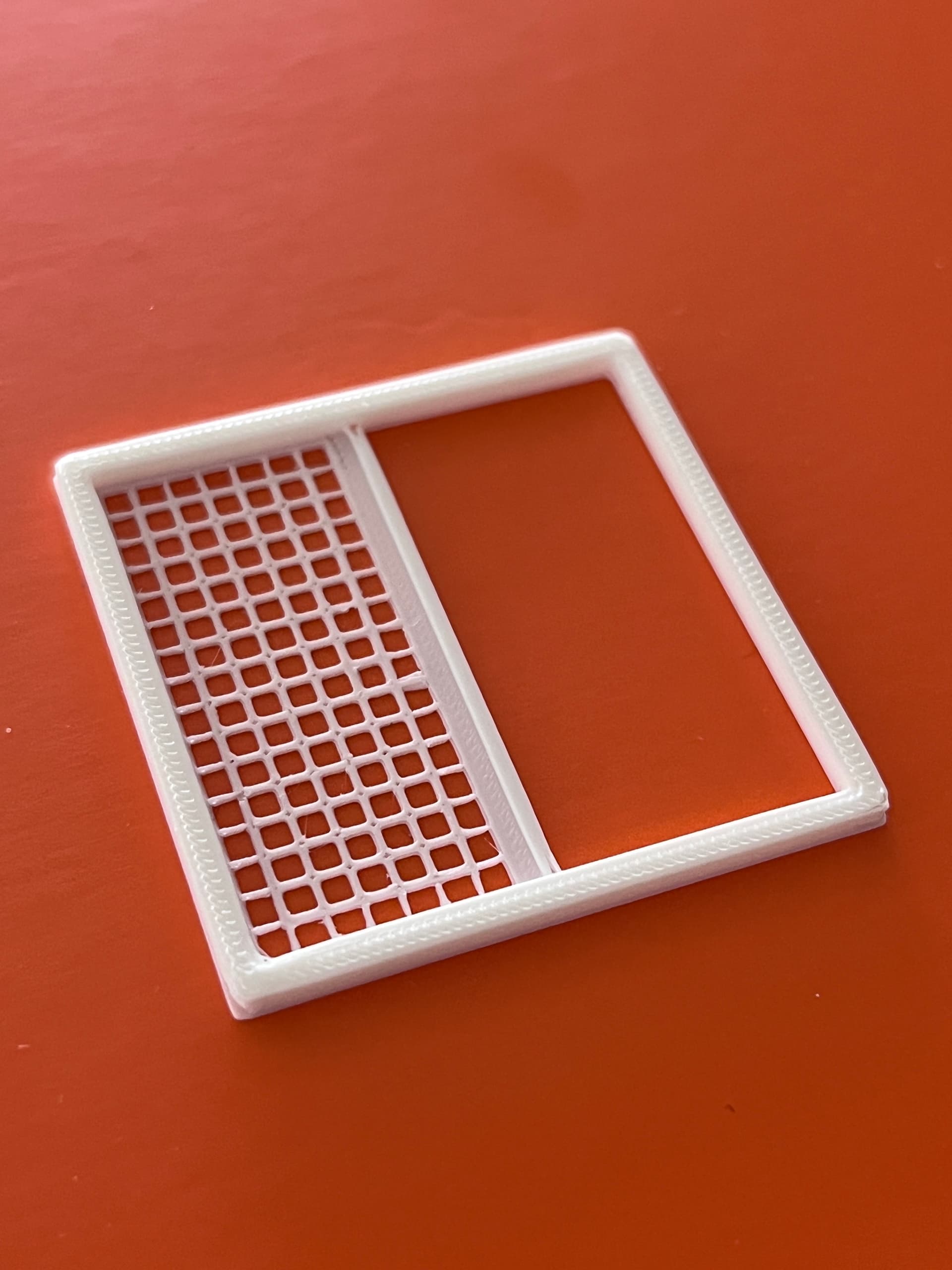
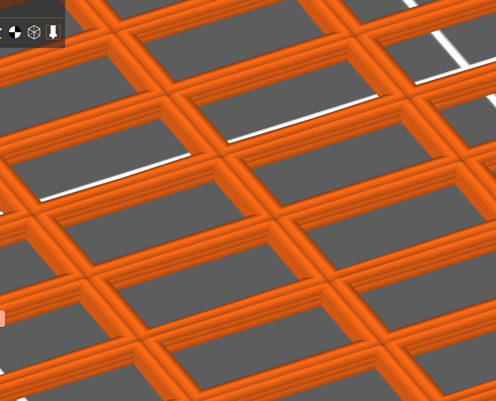
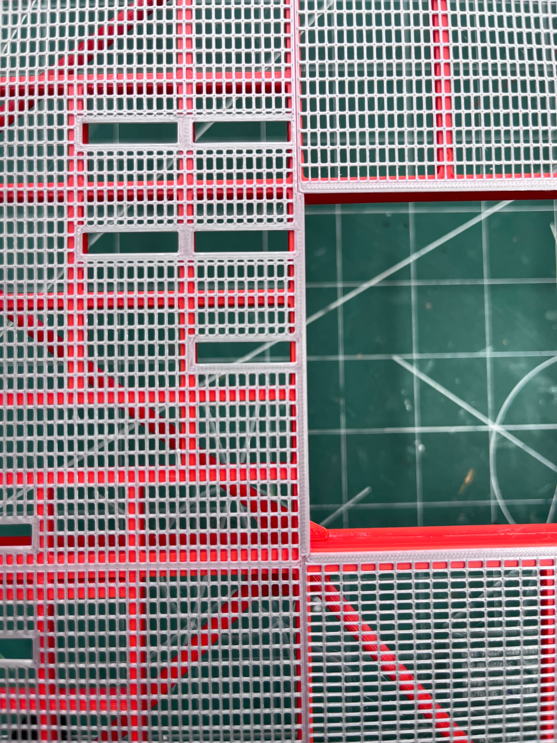
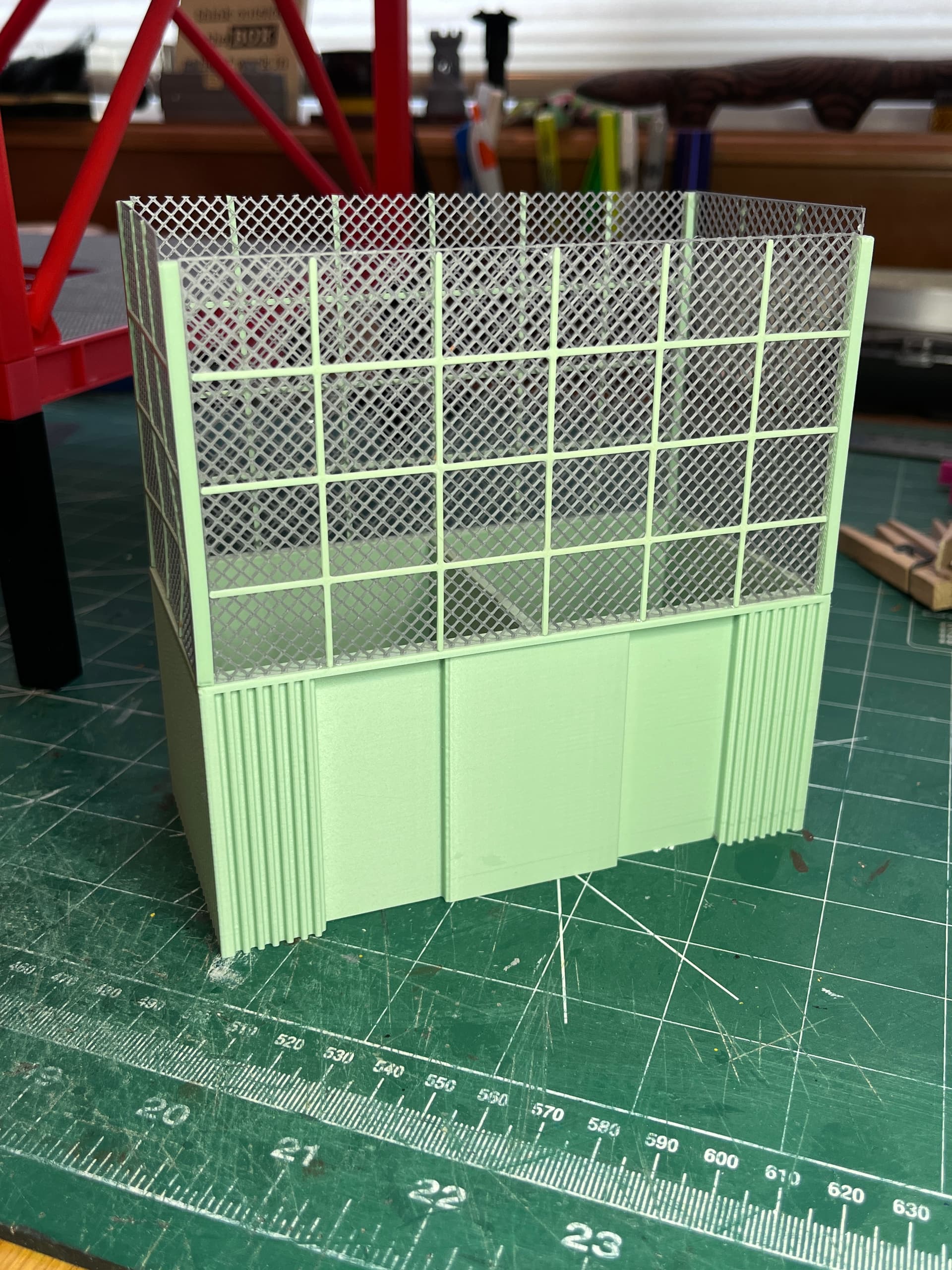
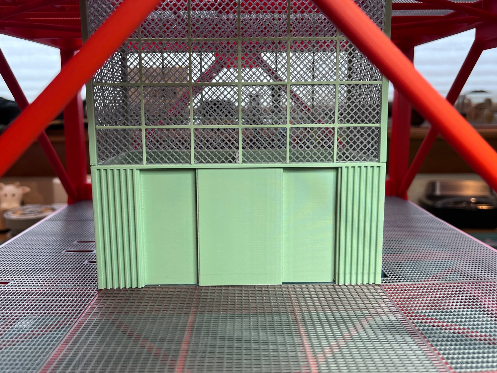
Armed with better printers and a 0.25mm nozzle plus the larger scale I will be able to get much better detail. Here is a test panel to see how much better I can make the side panels of the swing arms. This test panel has a 2x2mm square border. The mesh is 0.4mm dividers that are 0.25mm thick (2 layers). I expect most of the swing arms to printed with a smaller nozzle.
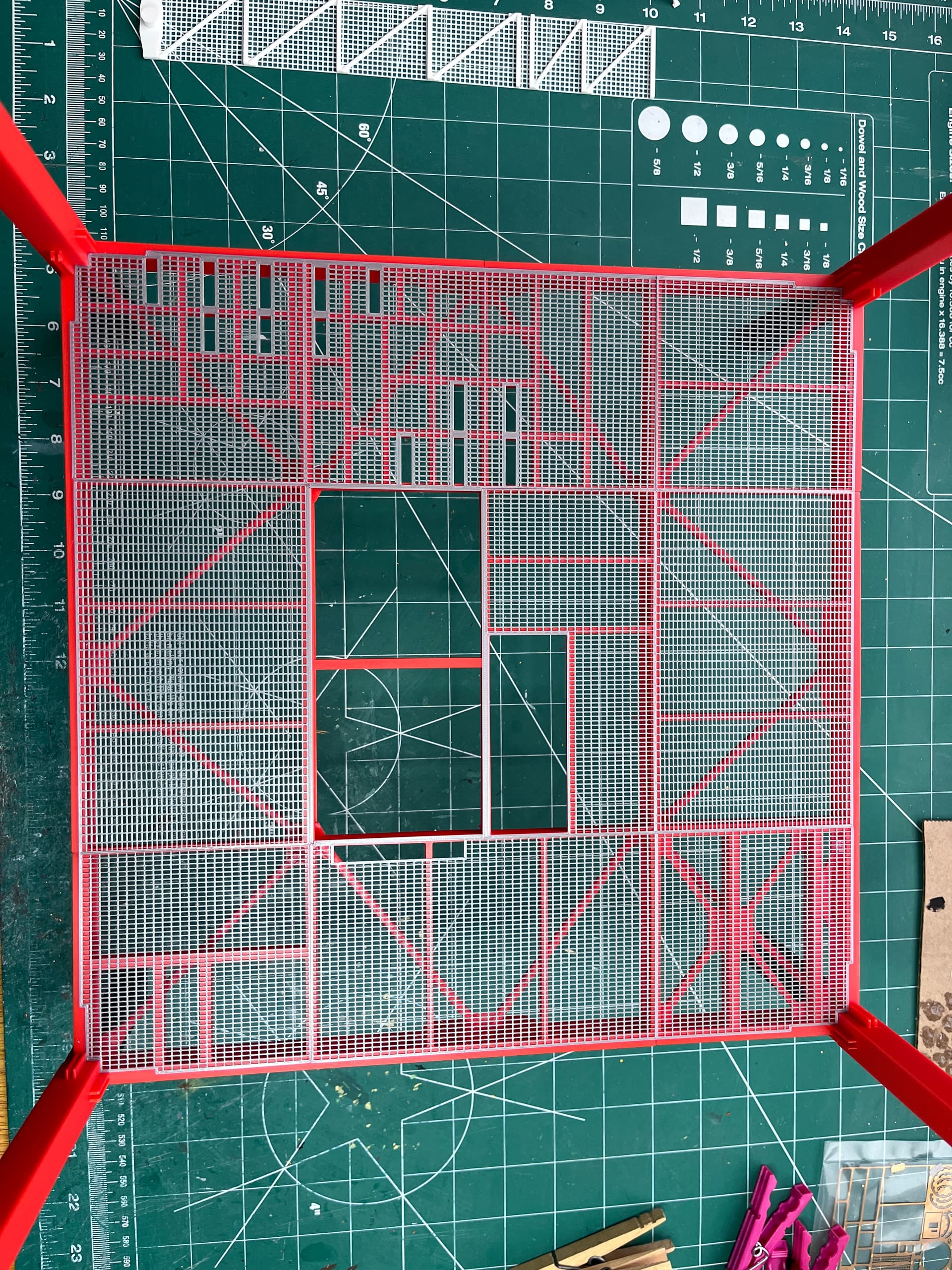
The floor grating is being completely redesigned. With the help of a better printer and a 0.25mm nozzle the result is looking good. The entire floor is split into four parts. Here is one of the sections test printed. The thickness is 0.35mm which allows for three layers.
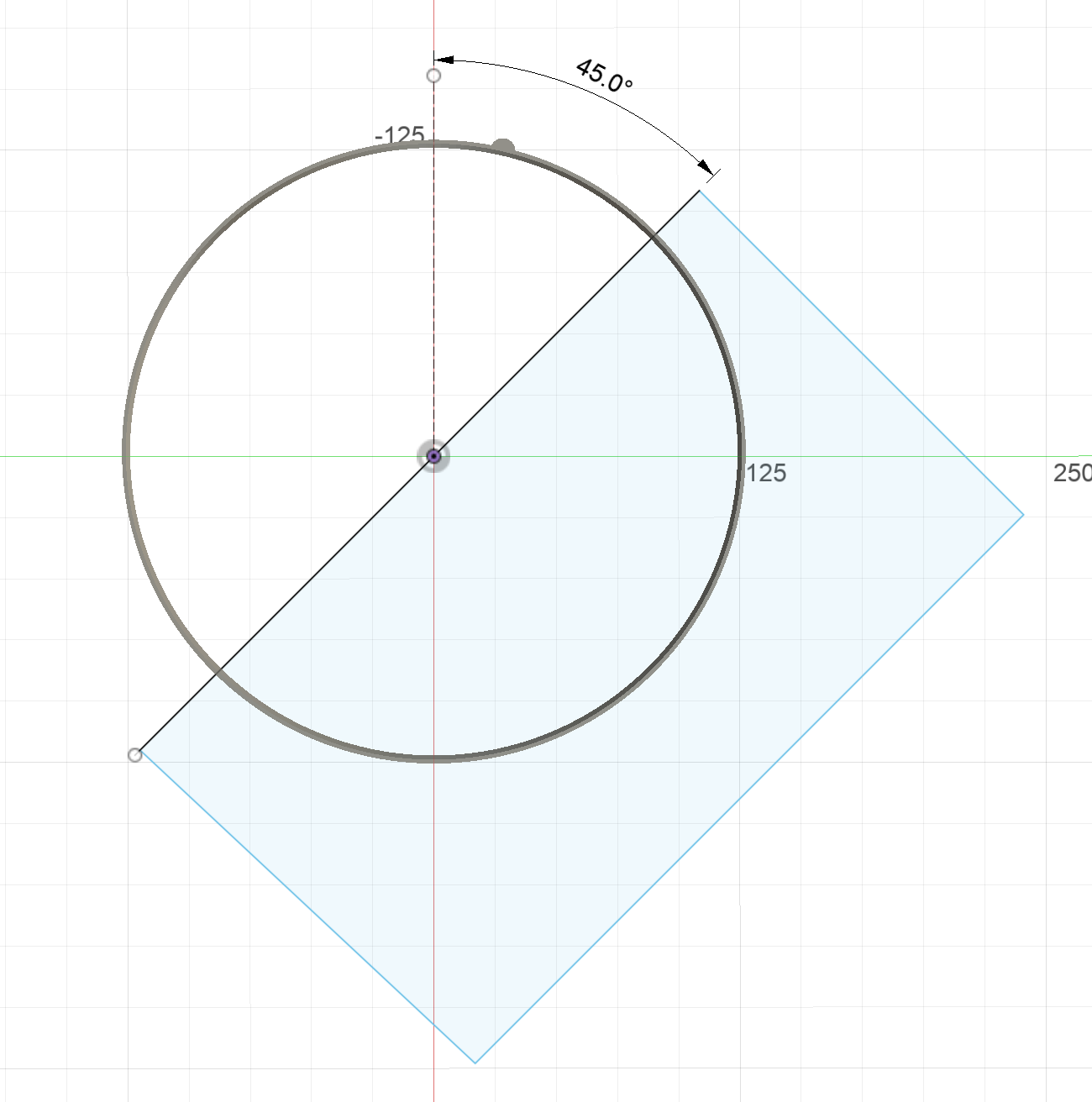
Working on slicing a portion of the Saturn V in half. For the Saturn V I purchased the STL files at this site: Aiming for the moon!・14 3D Models & STL Files to Download・Cults. The more parts I could re-use in the original model the better. This is a high quality detailed model of the Saturn V. There are 4 collections of parts that cost less than $10 per set. Since the license says “No modification or adaptation of the 3D model for public sharing or sale” I will be unable to publish these parts. The rest of the parts I am using will be available for free on Printables.com once the model is complete. If you want to build this model I suggest you purchase the model and do what I did to modify the parts. What I did to the parts is 1) scale up by 1.5 from a scale of 1/60 to a scale of 1/40 then 2) slice the affected parts in half. Notice that the parts are sliced at a 45 degree angle since the model’s parts are indexed 45 degrees off Side 1. Here is how I sliced one of the parts.
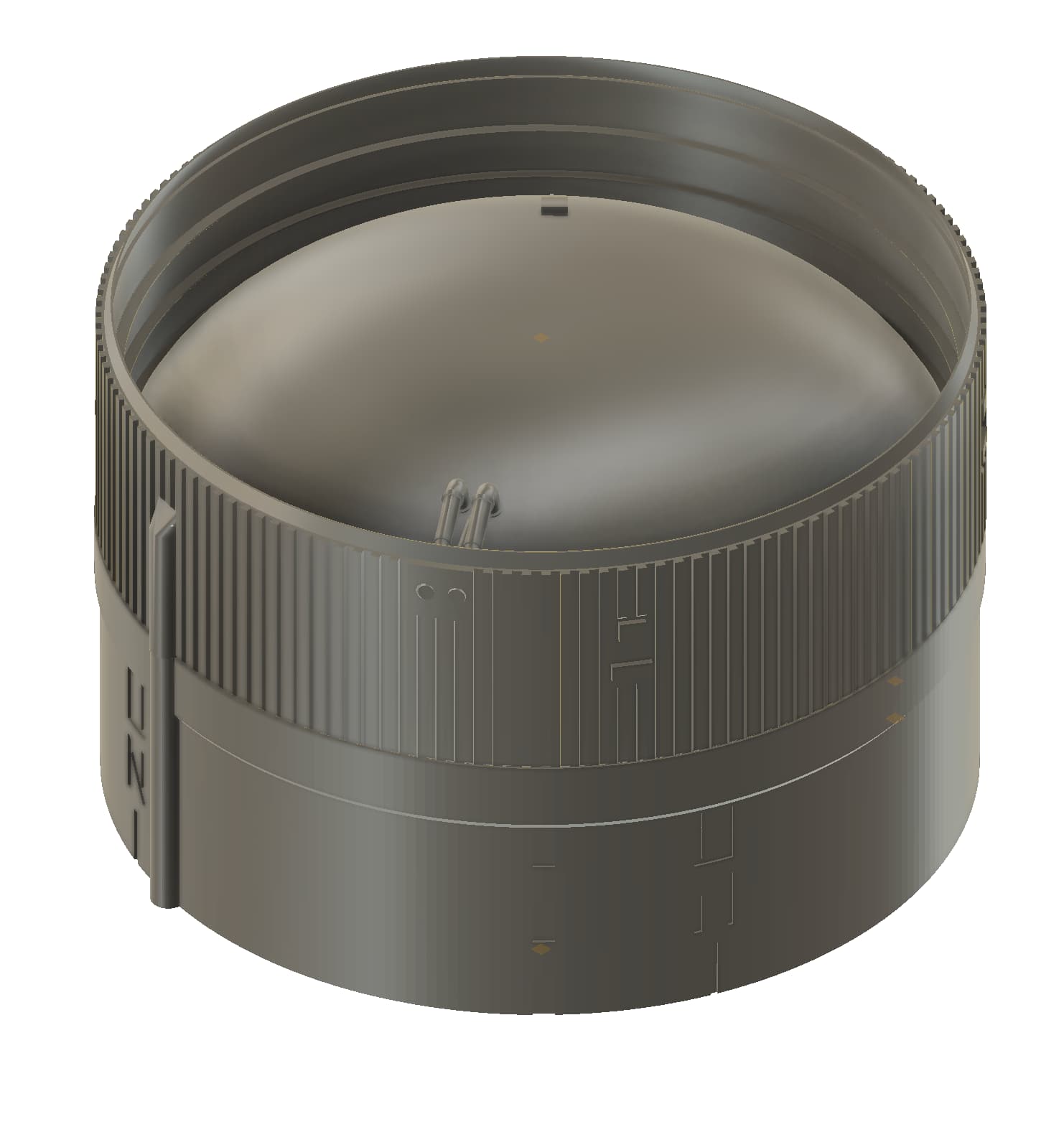
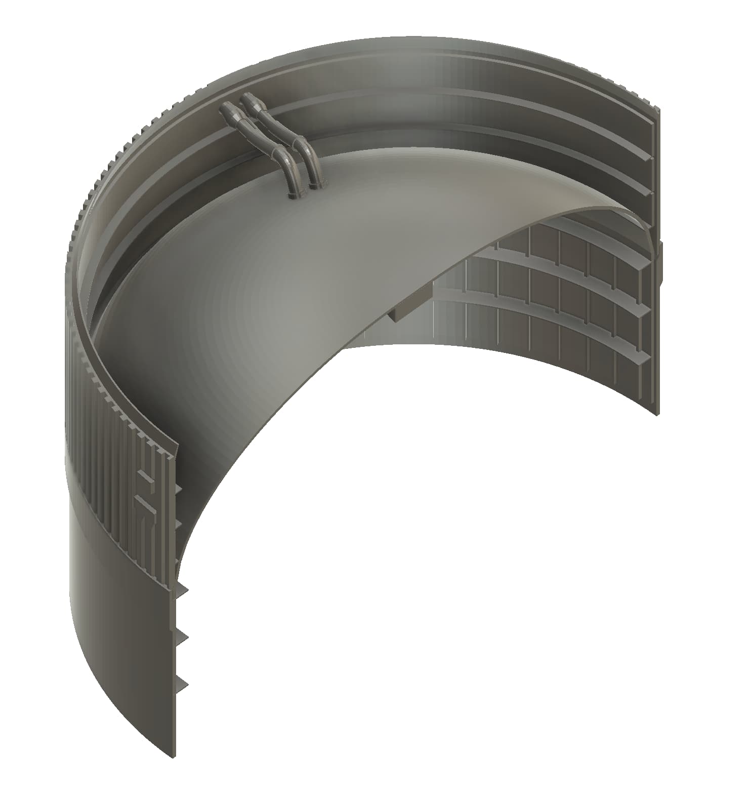
Here is the top of the stage 2 tank sliced off. The horizontal slice is 145mm below the midpoint of the connectors at scale. You can see the two connectors near the top going into the top of the tank.
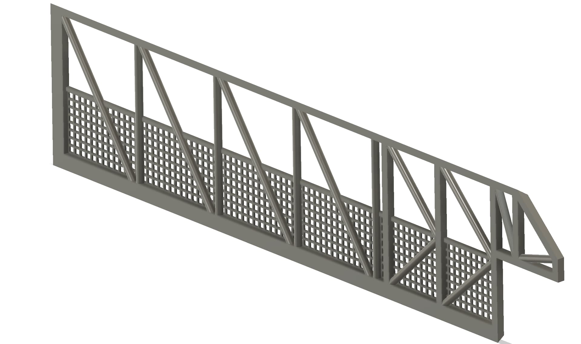
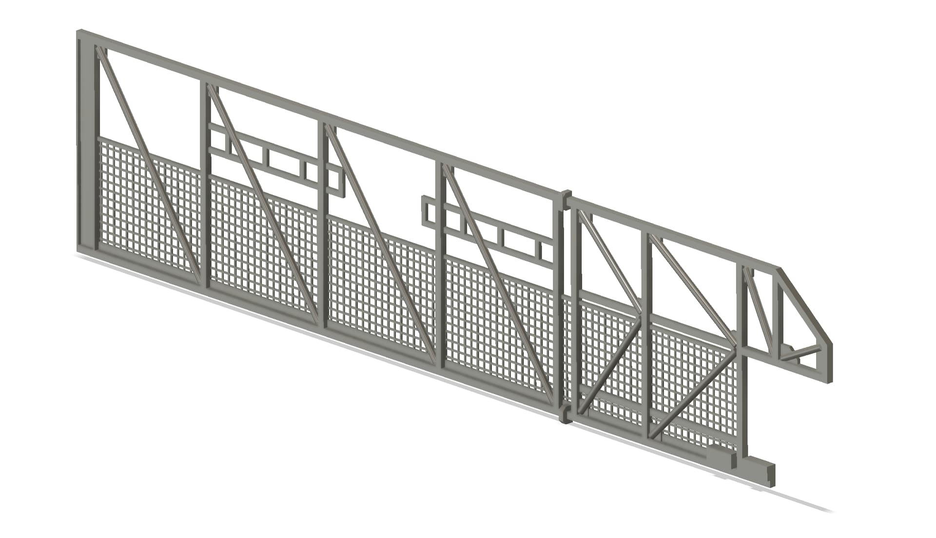
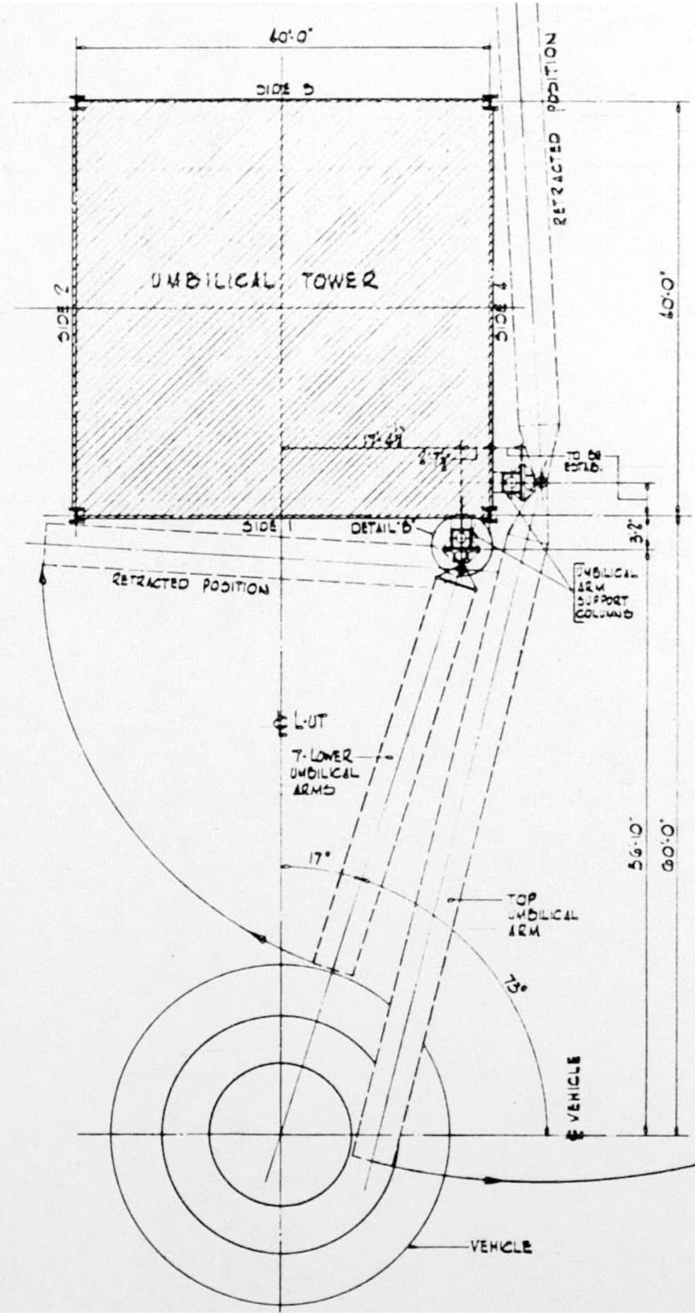
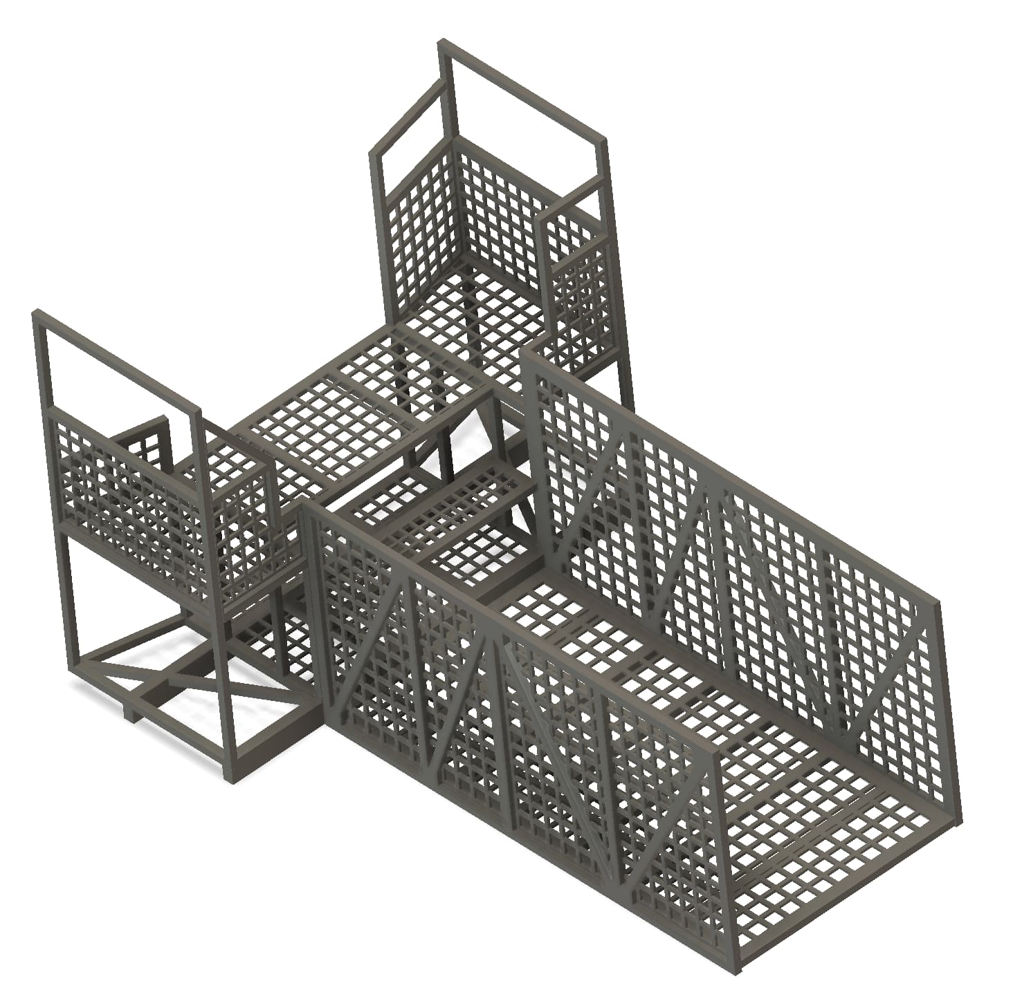
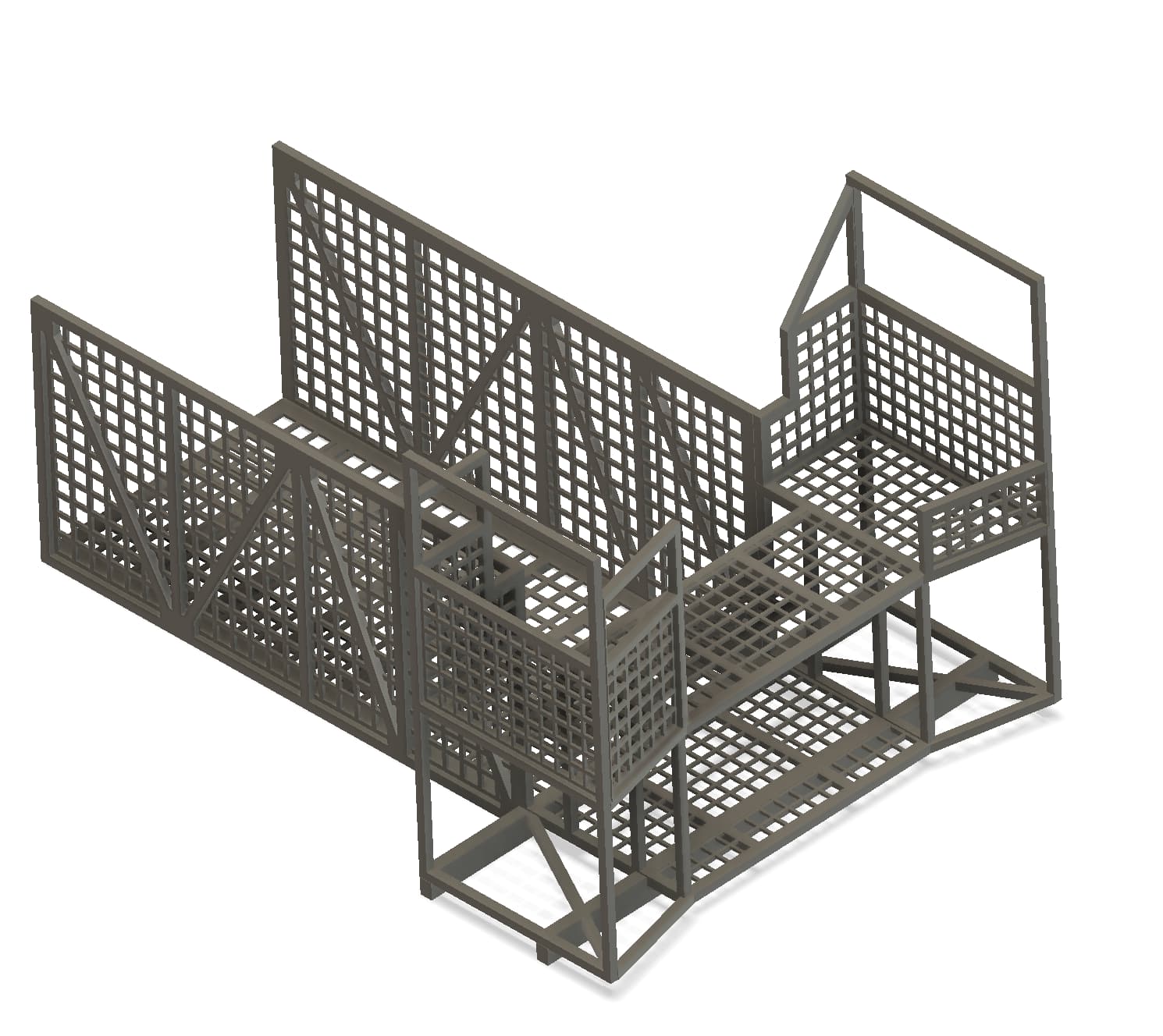
Here is the business end (service platform) of swing arm #5, the “S-II Forward” swing arm that connects to the top of the Stage II H2 tank venting the gaseous hydrogen plus electrical, pneumatic and A/C lines. Most of the swing arms share the same “fixed” swing arm structure consisting of the first and second element. This structure fits into the end of the fixed structure. When the arm swings out into position this service platform extends until it touches up against the rocket. The service platform allows technicians to walk out and attach the connector plate with all it’s various hoses and connectors to the rocket. With the connector plate in place, the service platform is retracted out of the way. Upon liftoff winches then pop the connector plate off the rocket and the swing arm is swung back out of the way.
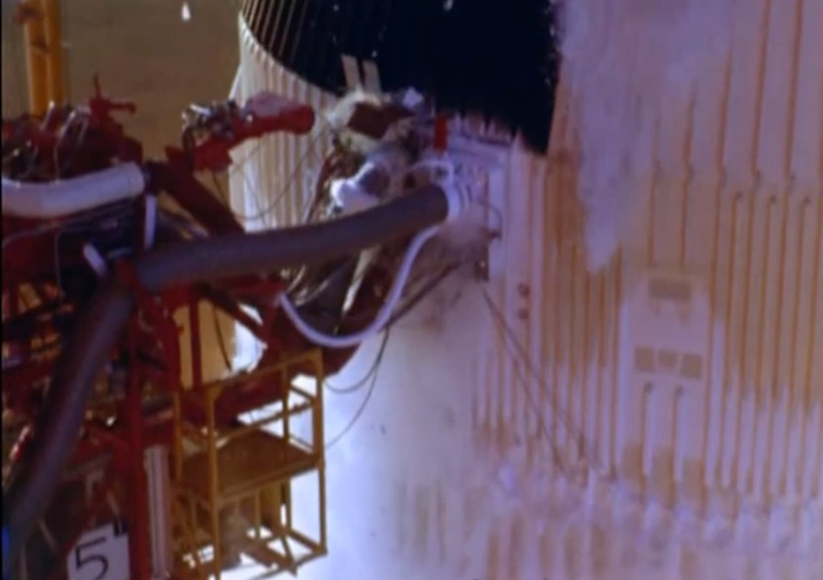
This platform is yellow and white (the portion that fits into the fixes structure). There are 14 parts that need to be glued together. Some additional small parts still need to be added including the bumper and a winch mast. Pictures and drawings are hard to come by. There are detailed NASA drawings for the first and second elements of the arm. For the most part I am using the work of Mischa Klement and his MicroArtwork along with drawings on TurboSquid by Stuart Howes. They are both great products with lots of details. A lot of hard work went in to the creation of these products. Unfortunately they do not agree on all aspects of the swing arms. This is due to the lack of technical NASA drawings and photos. Here is one photo I grabbed from an old video. It looks like it agrees more with the TurboSquid drawings so I have leaned in that direction. You can see that the main part of this service platform is yellow and the part that fits into the fixed portion is white.
And here is what I am calling the fixed portion of the swing arm. This consists of the first and second elements. There are detailed NASA drawings of this main structure. Some of the unique swing arm #5 components have been added. There are electrical cable trays on top and a pneumatic panel on the side. Note that for each swing arm, the end of the second element differs somewhat.
Here is the winch tree that sits on top of the end of SA5. This part does not have a flat part on it, lots of angles, lots of 3D CAD work. The part could not reasonably be sectioned into flat prints so I test printed it as one piece with supports. These types of prints are not as desirable as flat prints but it will have to do.
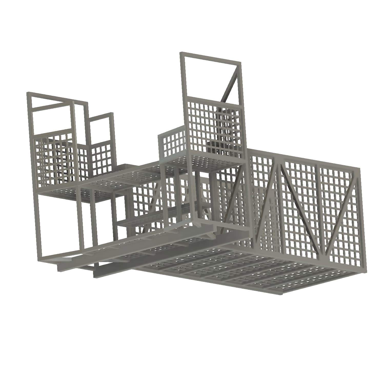
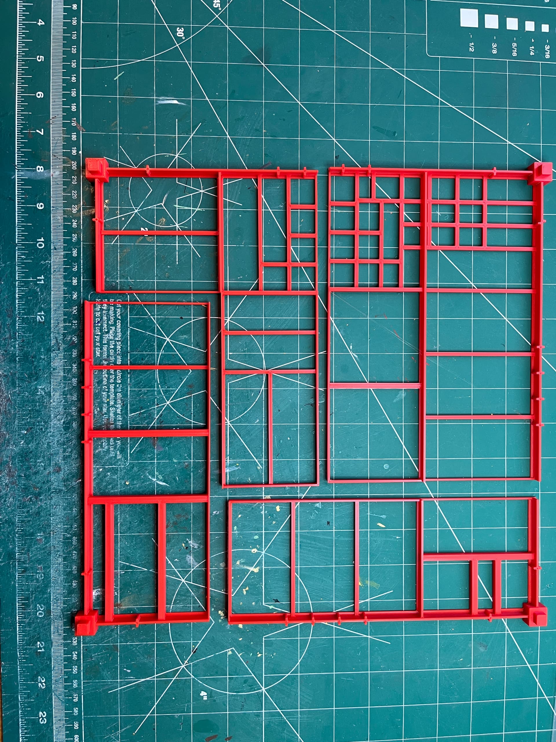
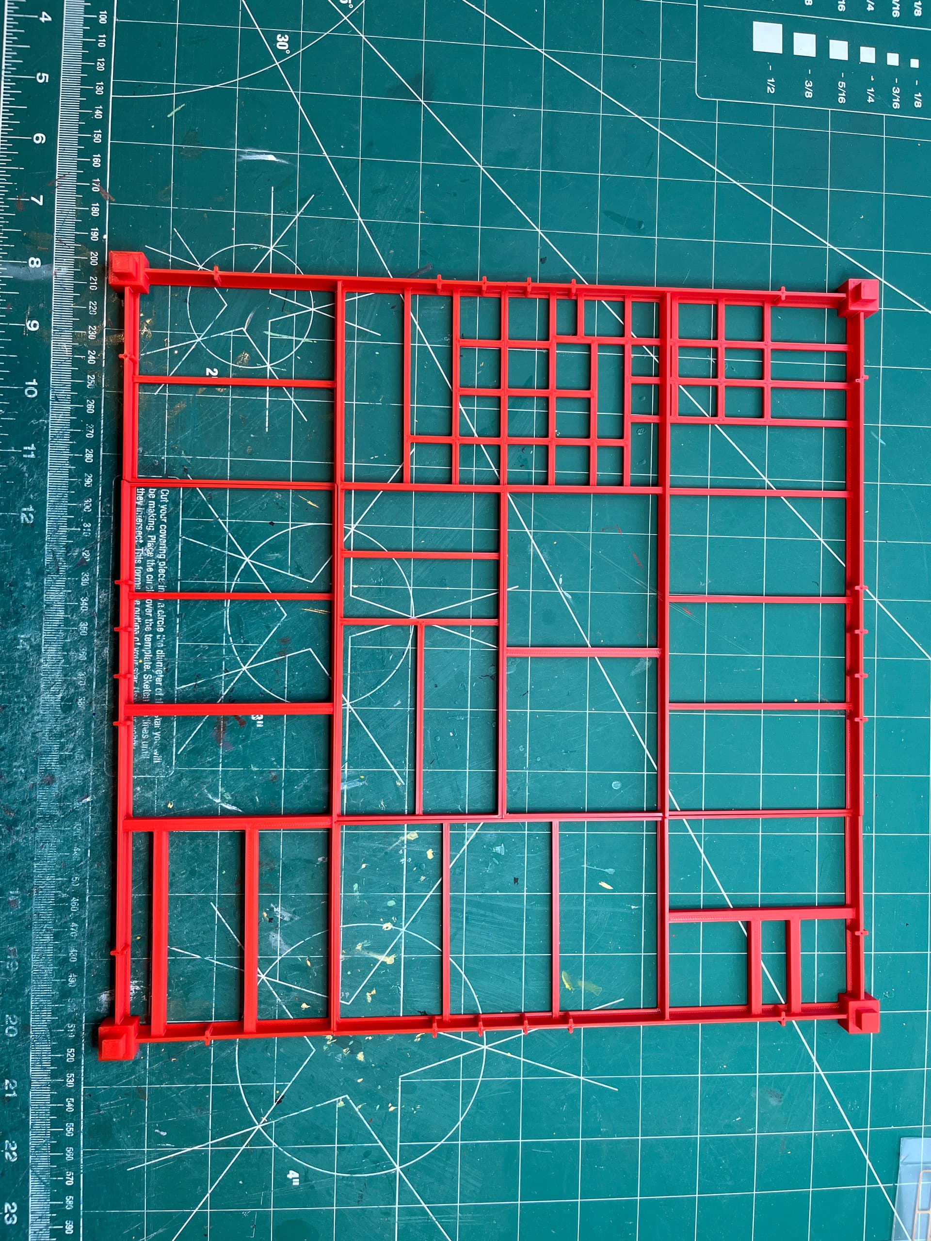
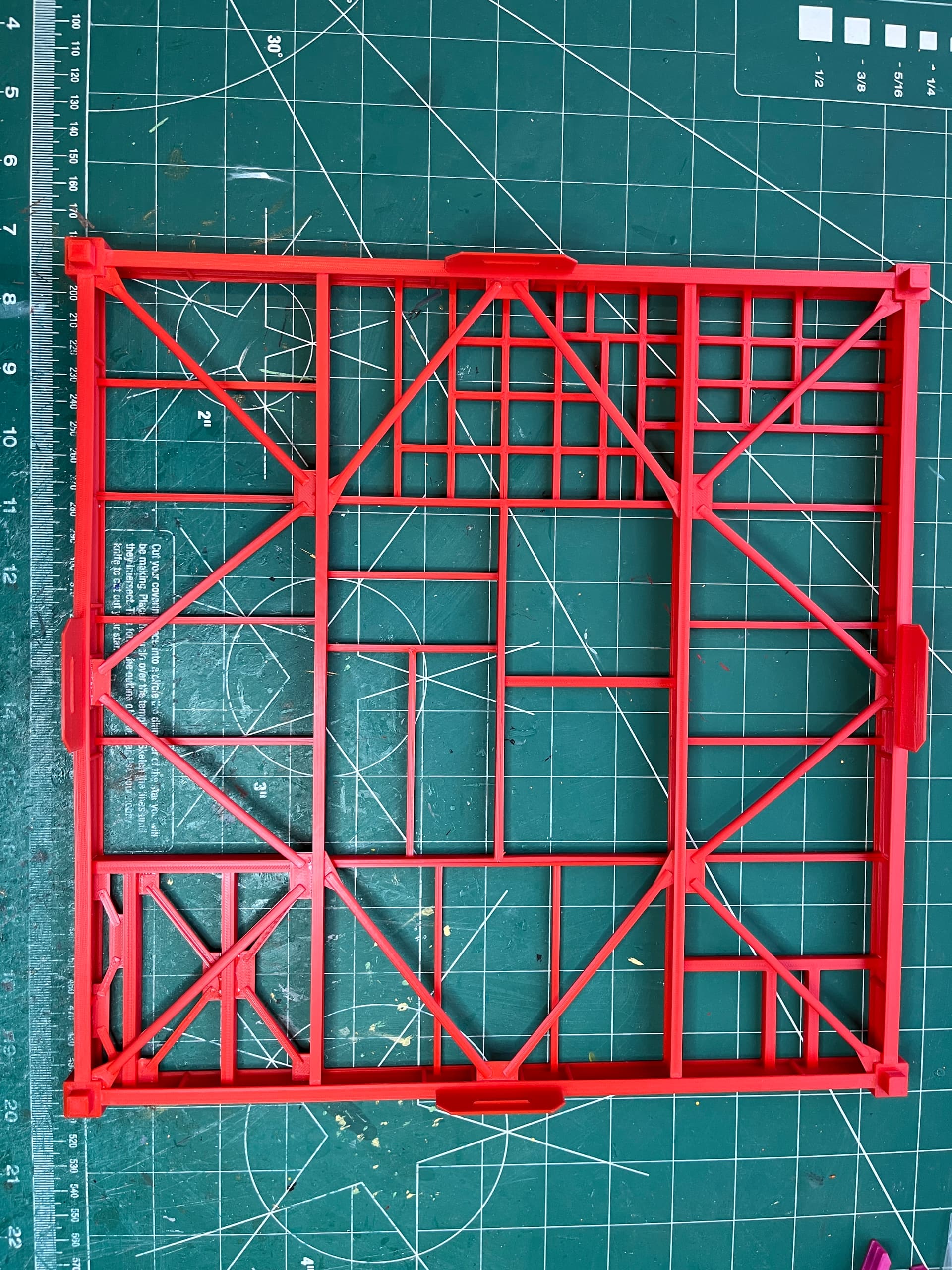
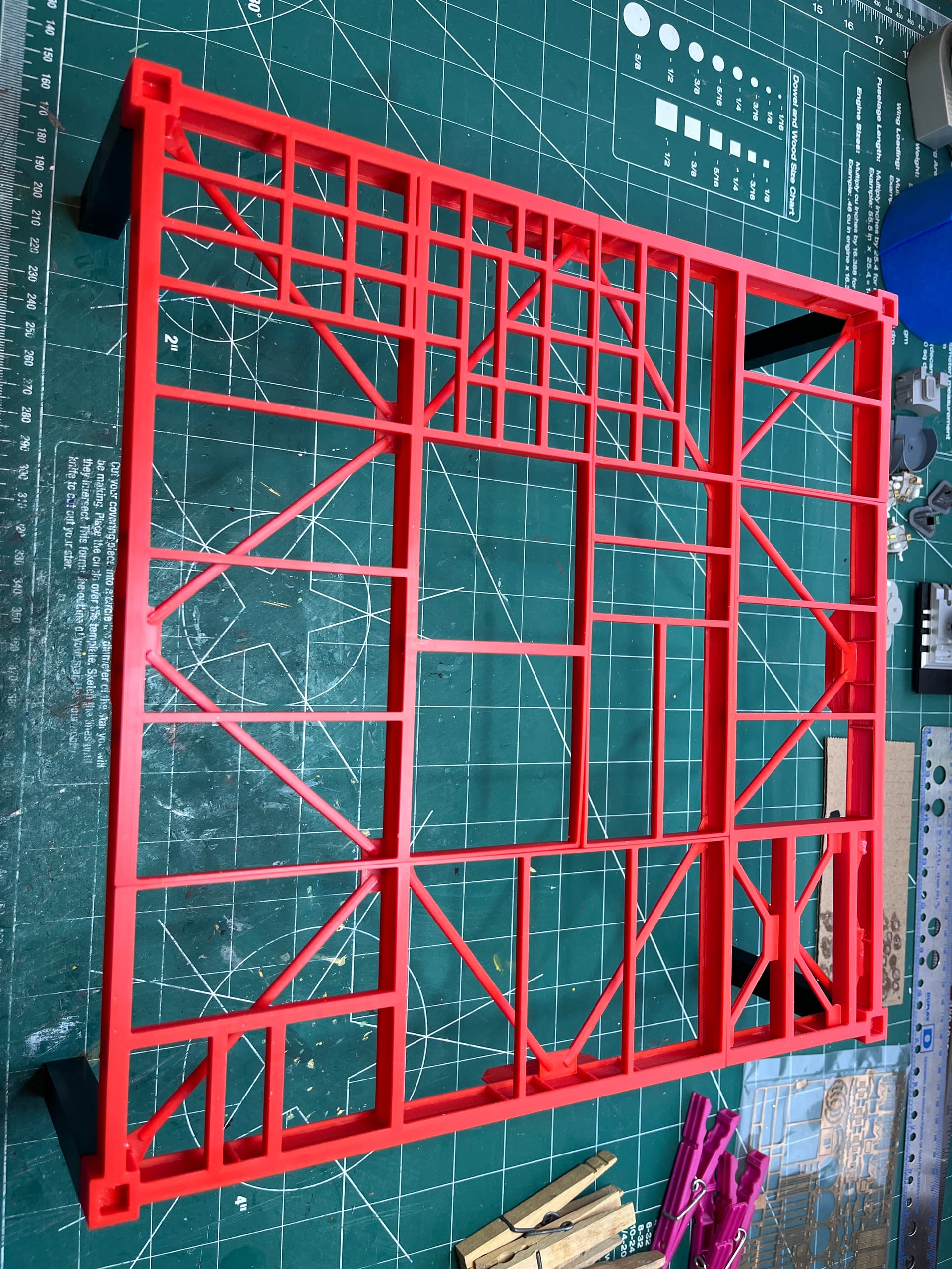
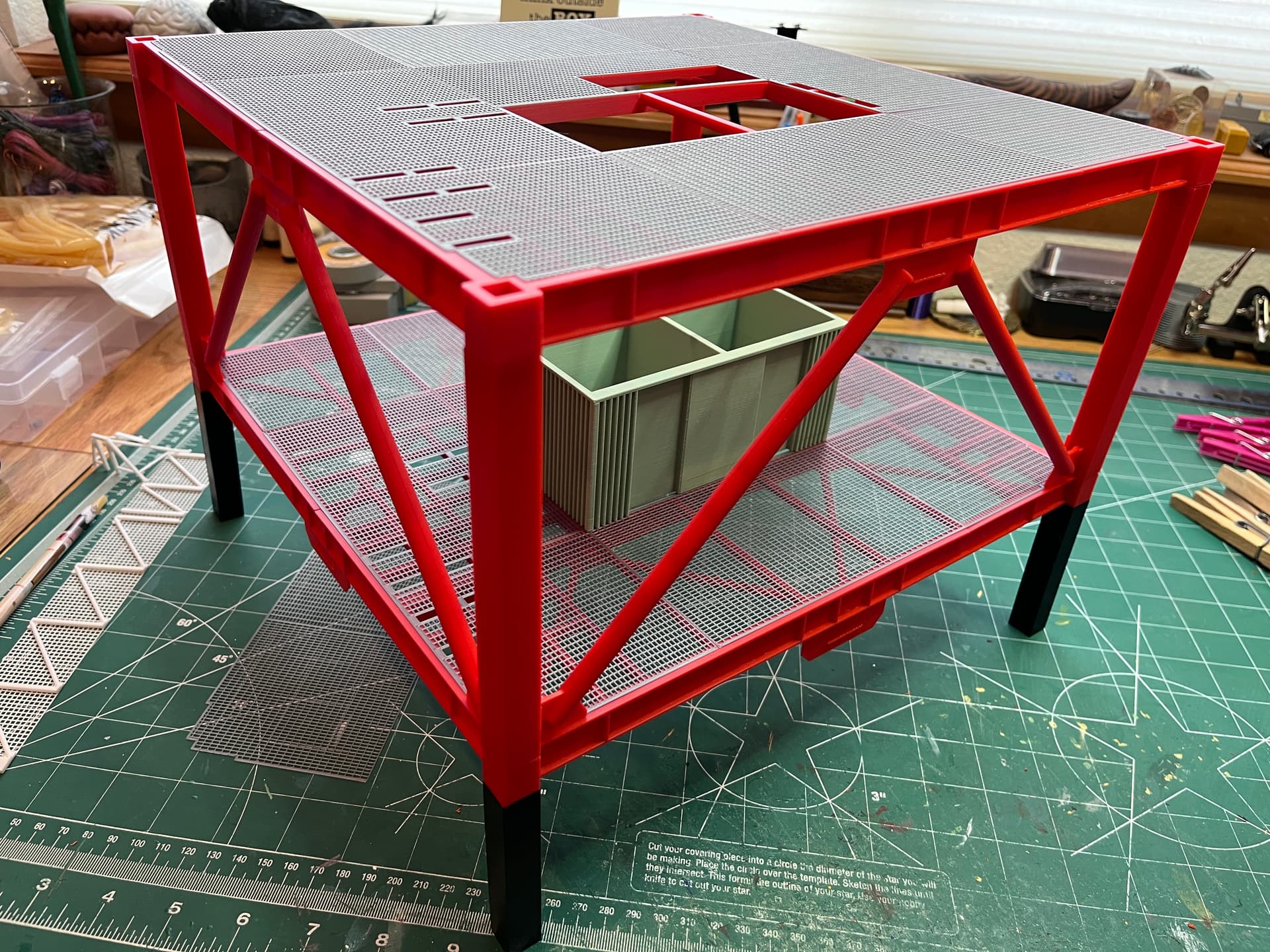
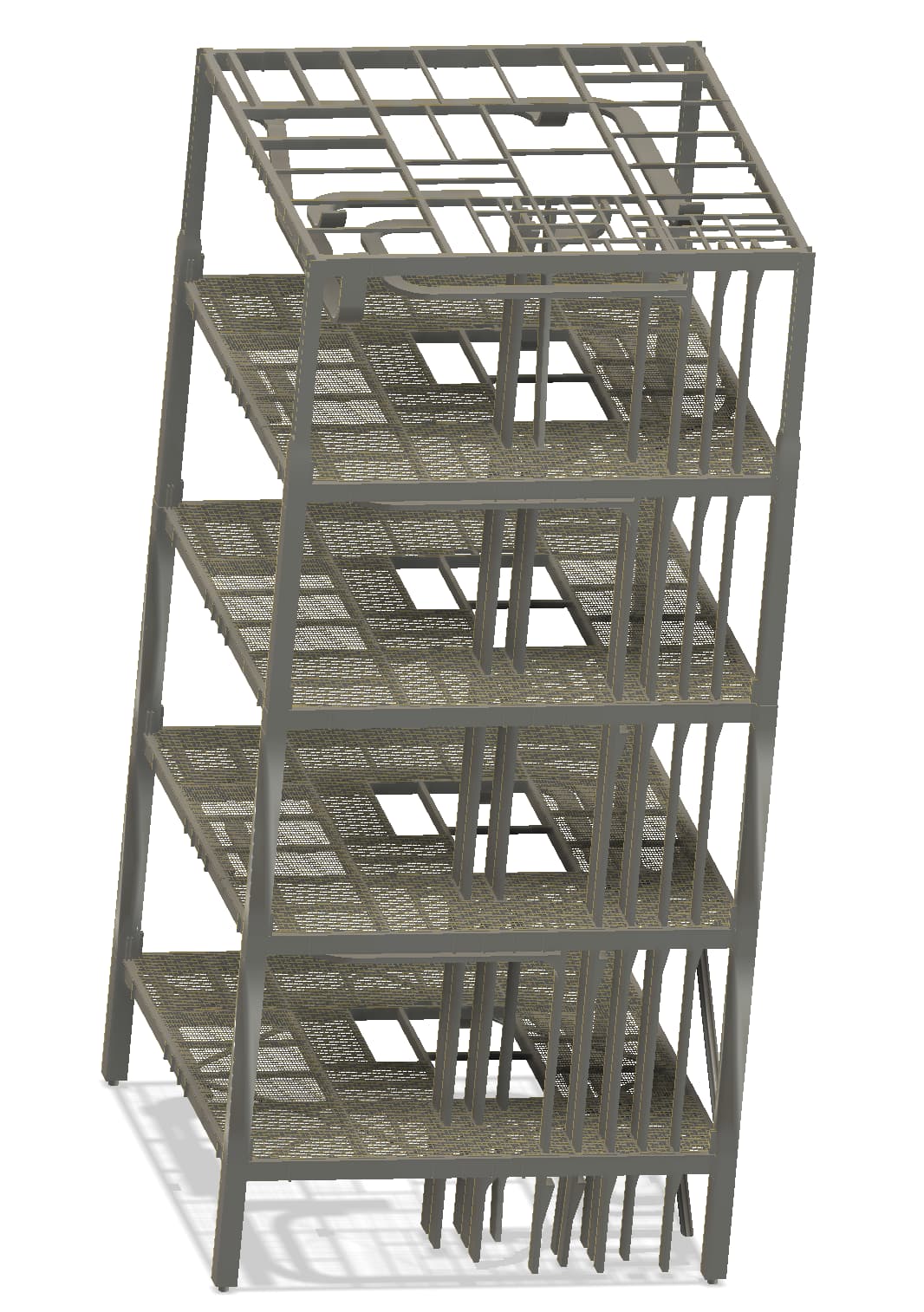
Now that the Lunar Module model is complete I can concentrate on this model. I have printed the four parts that make up the core of the level 200 floor structure. This is over a foot square, larger than my printers can print as one part so it is broken into four pieces. The underside of the I-beams can be printed as whole parts at an angle so those will help hold everything together. The final structure will have plenty of strength.
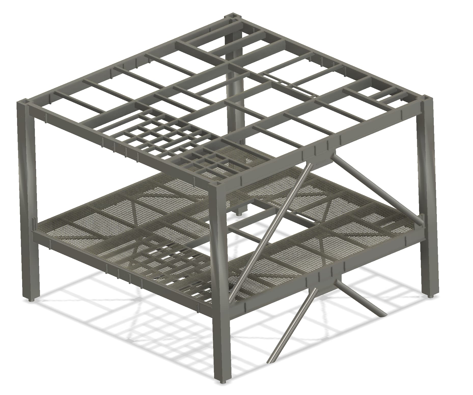
The original LUT was my first real 3D CAD project. My skills have gotten a lot better over the years. It’s scary to go back and see how green I was. So far I am making quite a few more modifications than originally though. Instead of printing and testing I have learned how to assemble the parts in Fusion and identify errors before ever printing. Here are the lower two floors assembled. Not all parts are included, just the ones required to verify fitment.
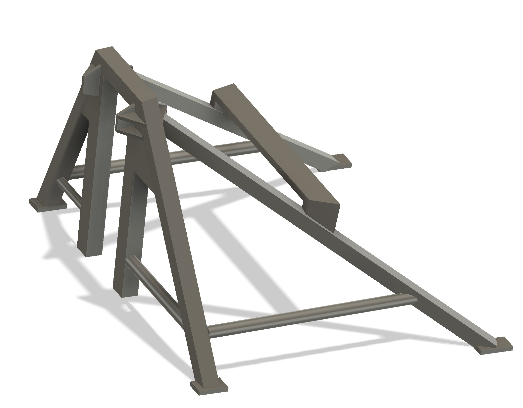
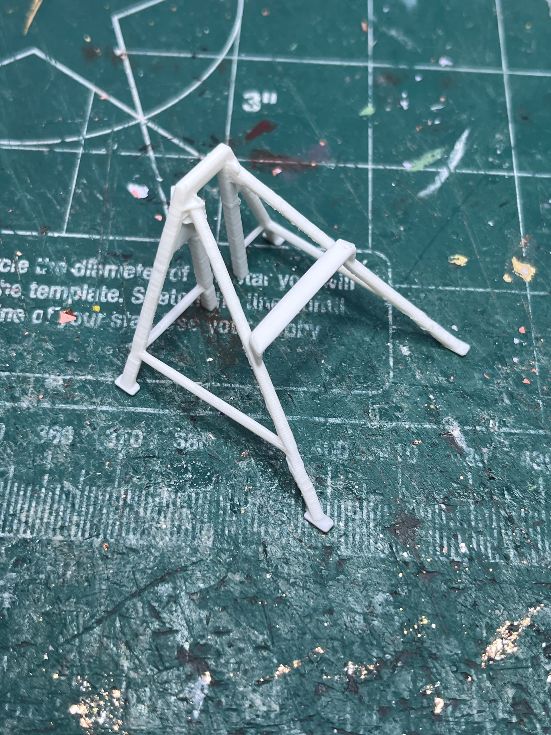
And here is the first floor structure glued up, the structure that supports the level 200 floor. The first picture is the underside and the second picture is the structure on temporary half legs. I won’t do a final print of these legs until the rocket section is complete and swing arm #5 lines up.
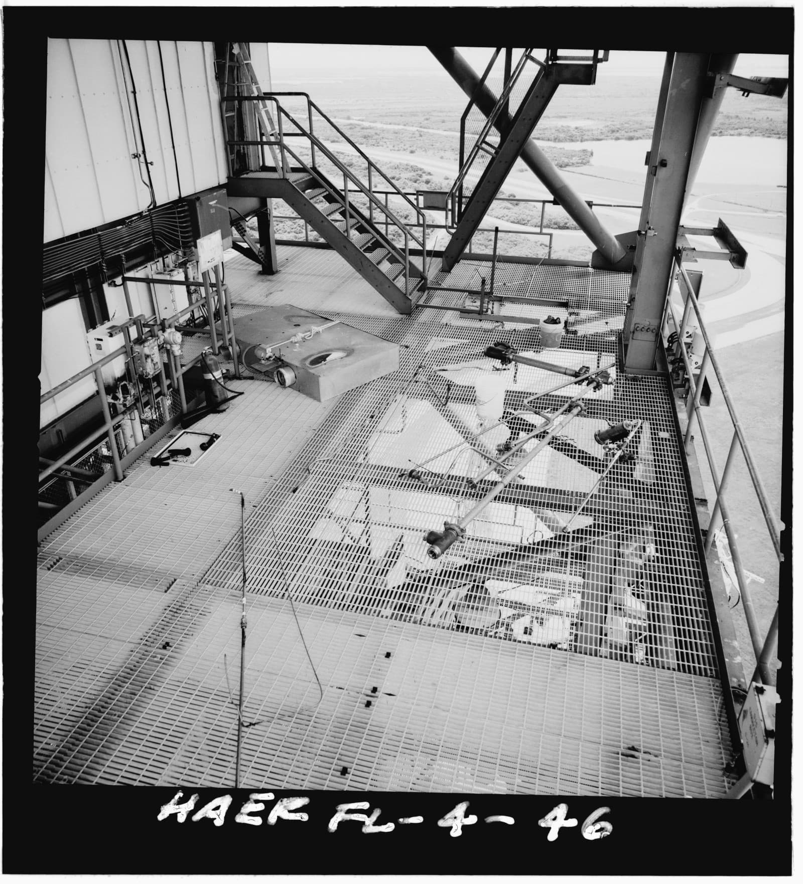
The level 200 floor grating is printed using a 0.25mm nozzle. This is light years ahead of the original model’s grating which was printed using a 0.40mm nozzle on a long gone craptastic printer. The grating, like the floor beams, was printed as four parts. In one picture you can see the joint. The grating has rectangular holes that did not all go the same direction. I included a picture of the original floor grating. This is level 360 that has the elevator mechanical room to the left. Unfortunately I do not remember where I got this picture. I believe someone posted it on the LUT Group web site.
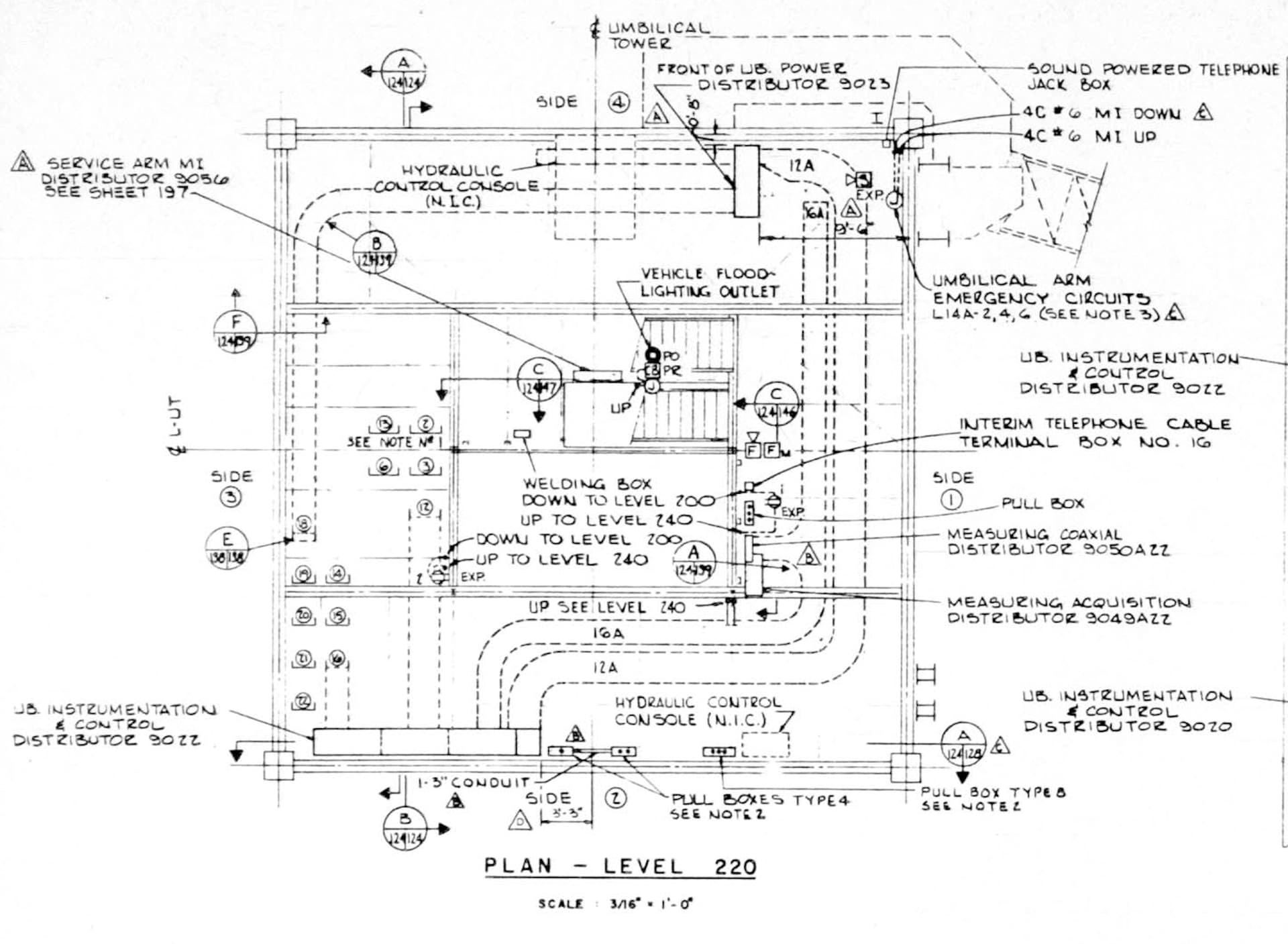
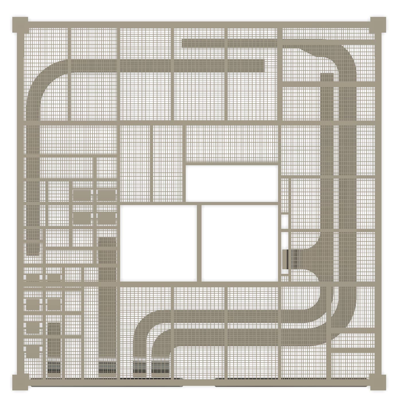
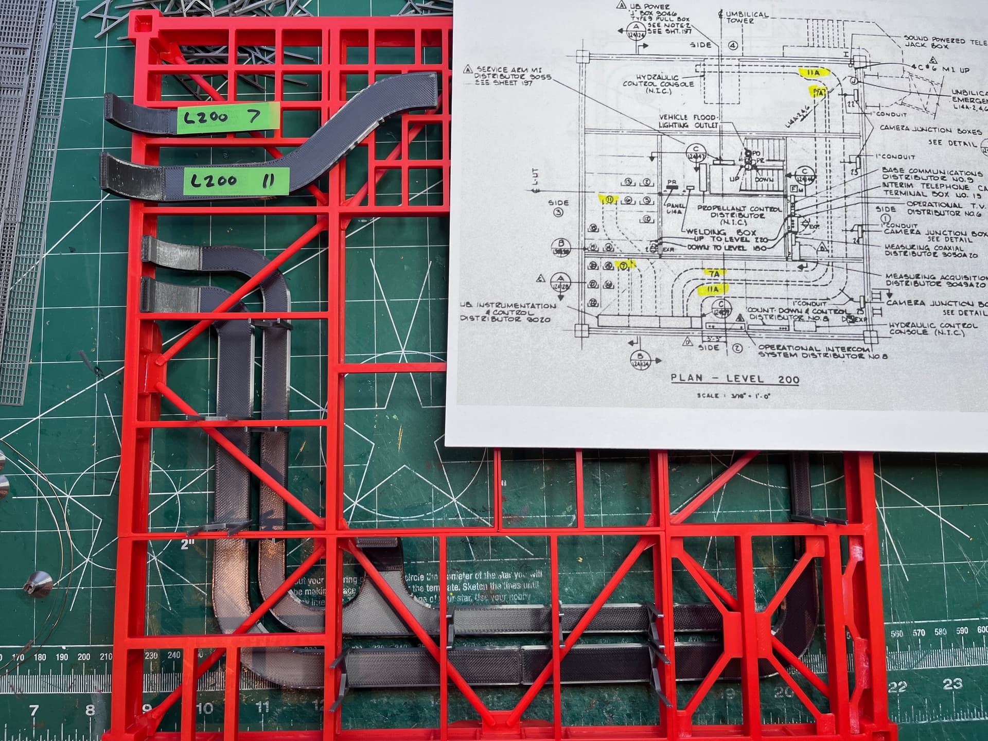
The cable tray redesign is complete. The original model did not have openings in the floor grating so things were not as exact as they could be. Now with floor holes everything needs to line up exactly. Here is a picture of the level 220 floor and the cable trays underneath, both from a NASA drawing perspective and as designed. The only parts that are not exact are trays 12A and 16A on side two are not as close to the elevator shaft as shown in the drawing.
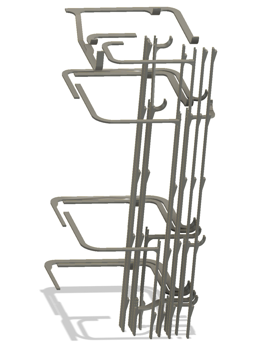
Redesigned the upper part of the elevator to make it more to scale, lighter and airier. The bottom half is the same, just scaled up. The elevator shaft consists of 9 parts that are glued together. The sub-assembly is then loosely set in place for now.
The elevator J-boxes and most of the equipment was created by Aviator67. For the J-boxes I had to lengthen the conduits 15mm. Other than that I expect all the other equipment will just need to be scaled up. Here are the scaled/lengthened J-boxes in Fusion.
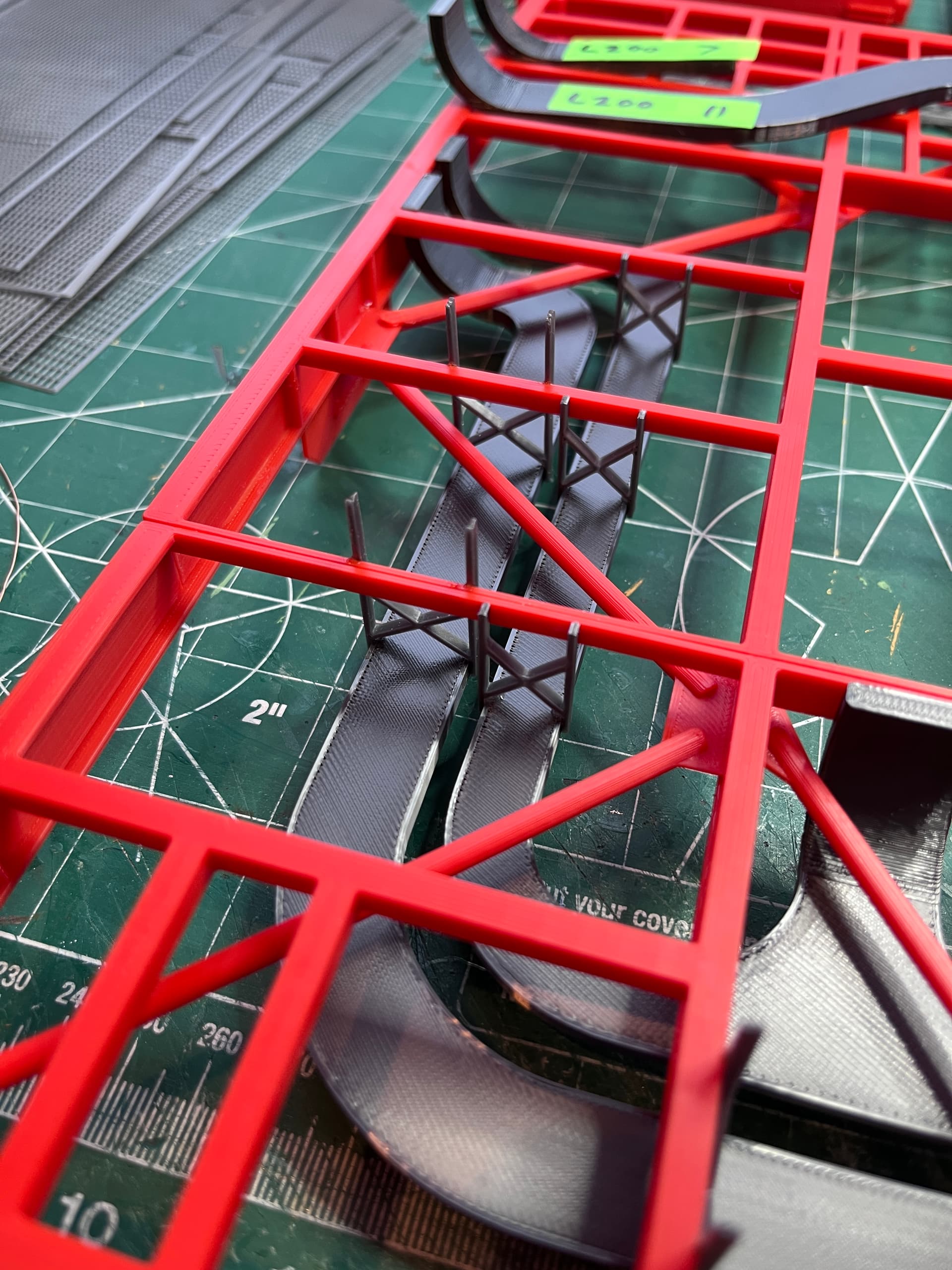
Before I can add the lights to the underside of the floor structures the cable trays need to go on. I’m using the same process that was used on the original model. The underfloor cable trays are positioned and glued on using the drawings in the NASA Mechanical and Electrical Installation document 75M-05121, pages 124-126. You can see the light placement on pages 133-134. The exact light placement is thwarted by the cable trays but I will try to position them as close as possible.
The cable tray hangers are made a bit long so they can be positioned and glued on with the cable tray at the correct height. The ends are then cut off flush before the floor grating goes on.
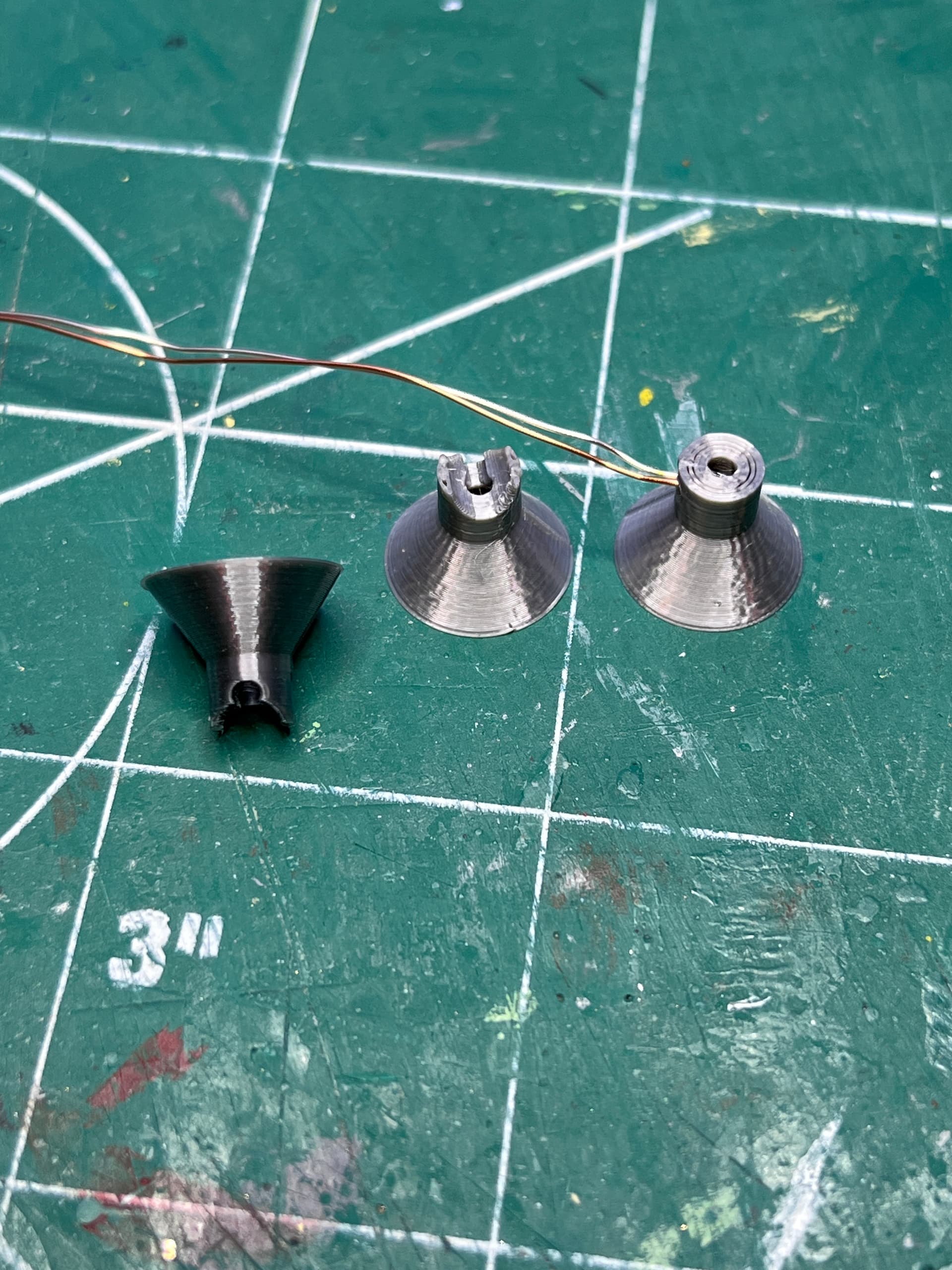
The hoods were modified. There are two types; flat mount and tube mount with holes out the side for the wires. With wires this small they should all but dissappear.
With the original model the resistors were placed alongside the light and they really stuck out. With this model the plan is to route these small wires along the pipes/I-beams to the elevator housing. In the original model there was a wiring harness that went up through the elevator shaft. For this model the plan is to hide all the wires and resistors. The plan for the elevator shaft is to add the interior parts supplied by John Huggins. There are vertical boxes that have the tracks to position the elevator cars. I have modified those parts to hollow out the lower section. This is where the resistors will reside. A little larger wires will then run from this box out to the vertical wires that will run through the hollowed out 12" braces.