Love, love, love it. I absolutely love it. This does really require some “ropes” to do such a magnificent replica and a lot of patience and dedication together with finding all the right materials to do it.
Fifty thumbs up… if only I had fifty hands… ![]()
![]()
Absolutely a masterpiece. Need I say more? I am so jealous… ![]()
![]()
![]()
I’ve found and purchased the STL files for the 1/144 crawler and launch pad. I also bought the 1/144 scale platform tower from Revell. the goal is to reproduce that historic day on April 12/82, and because I’m crazy and like to punish myself, to light the whole darn thing…
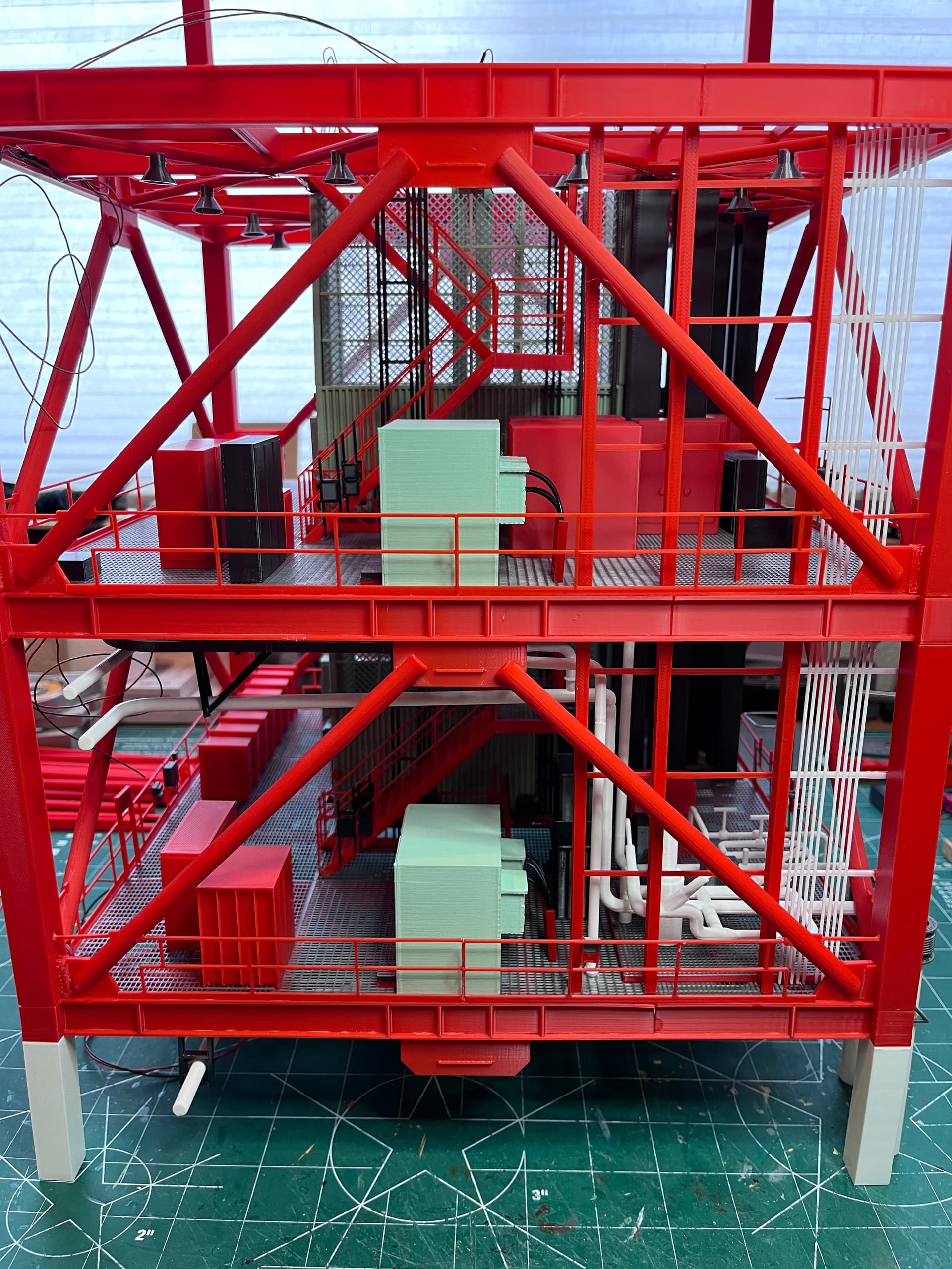
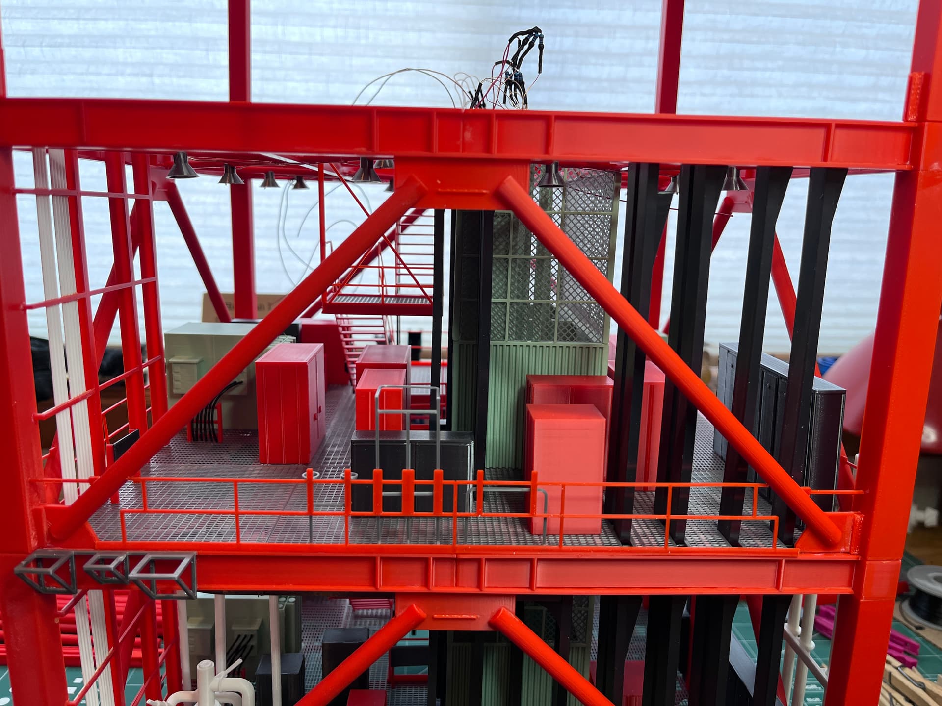
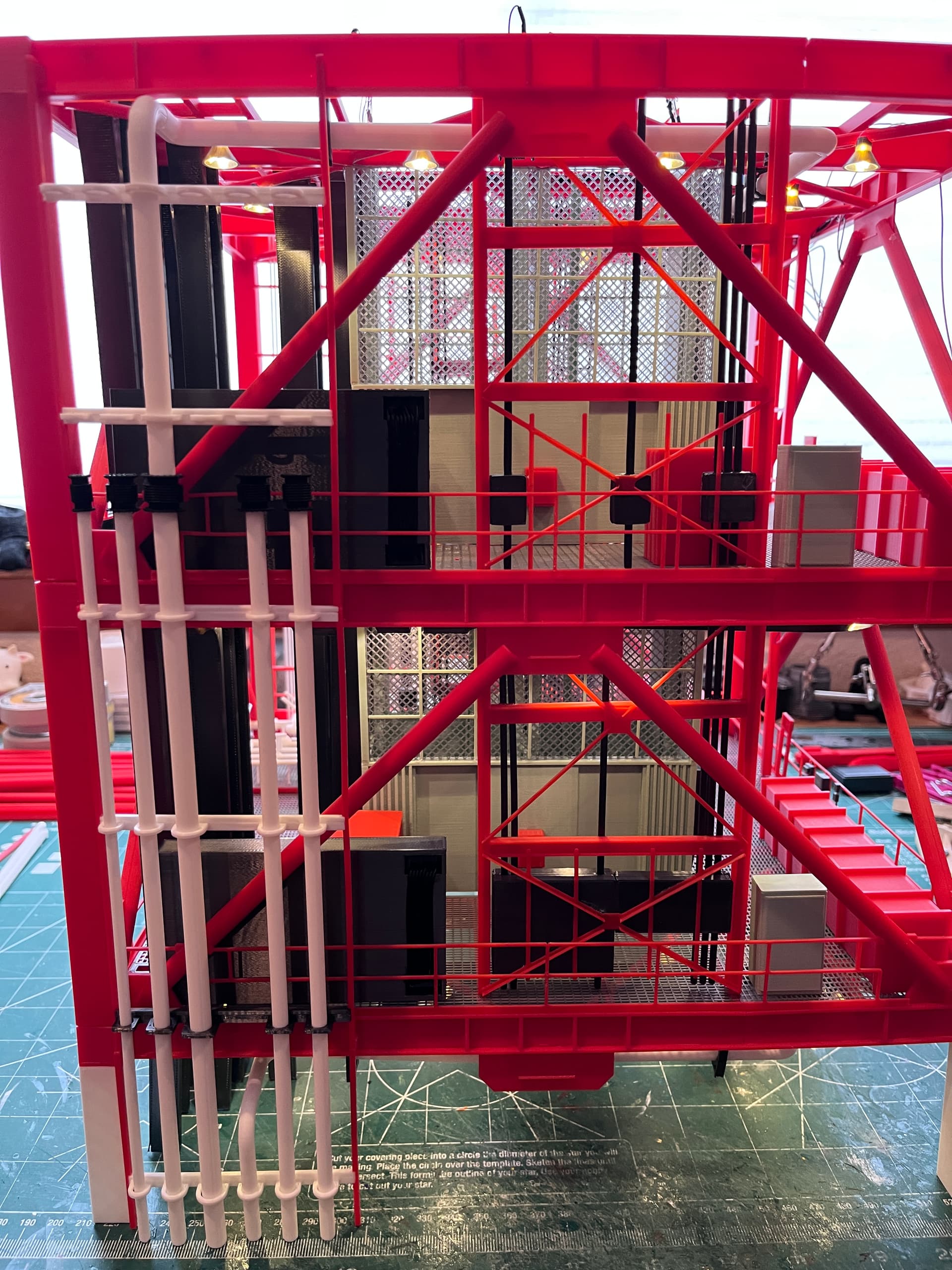
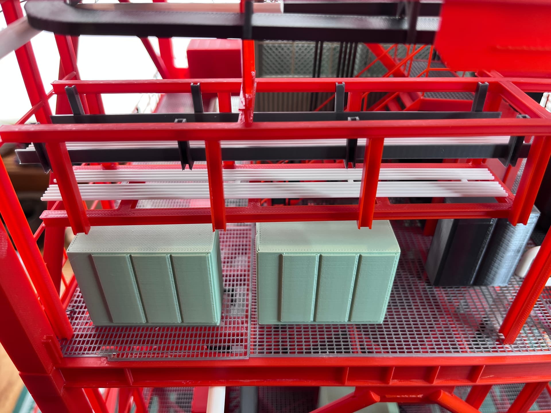
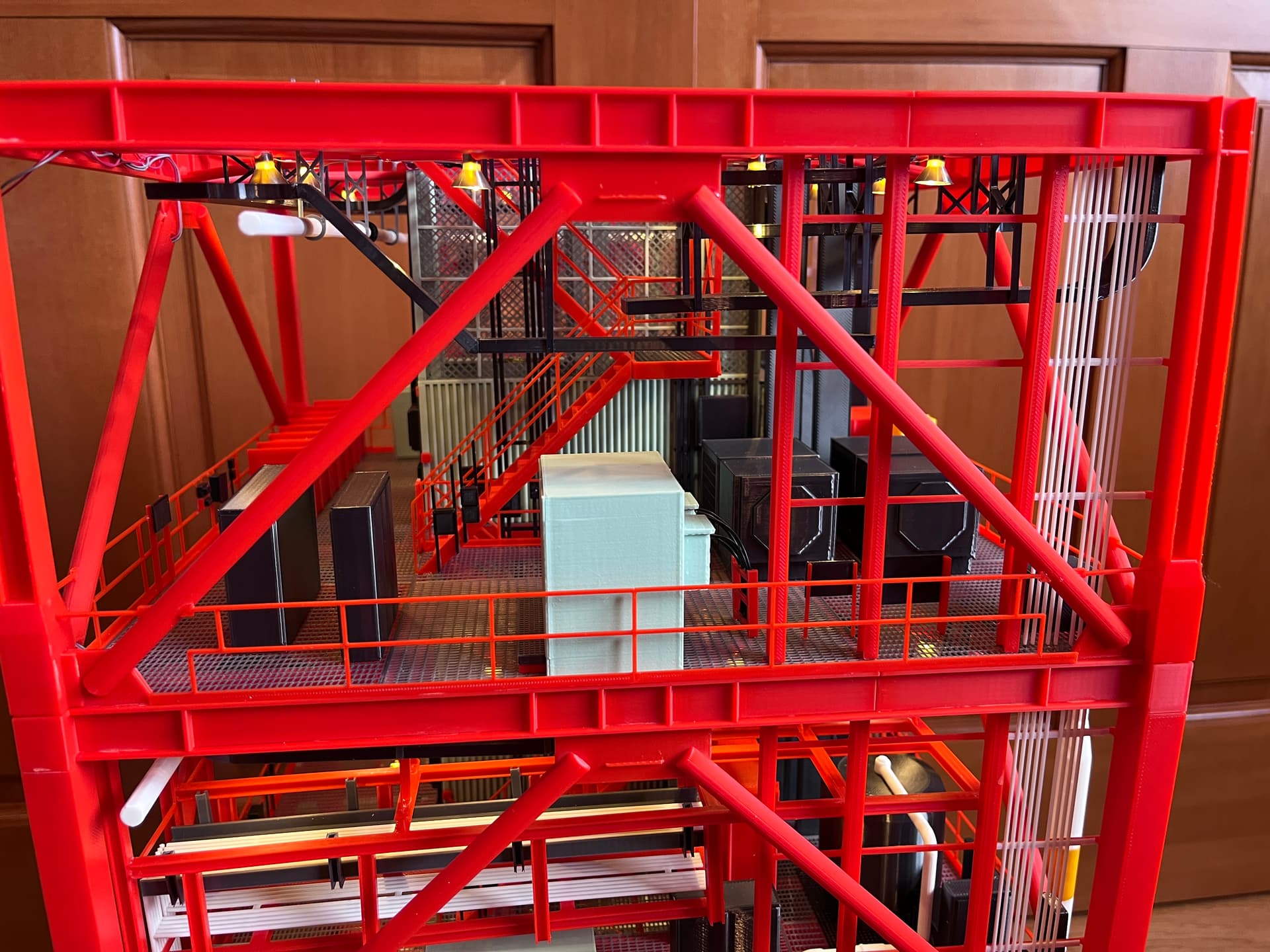
Back to the model at hand… I have most of the inner equipment for level 220-240 installed. There is also an inner rack going up the right side of Side 4. There will eventually be some outer hydraulic pipes that also attach to these racks. One of the pipes feed the large green boxes which are hydraulic devices that drive the swing arm retract mechanisms which are the long boxes on side 1. Some of those parts are the same as the next level down since both these levels have swing arms. The valves for both swing arms are the next level down. This level has a whole lot of cabinets.
3 Likes
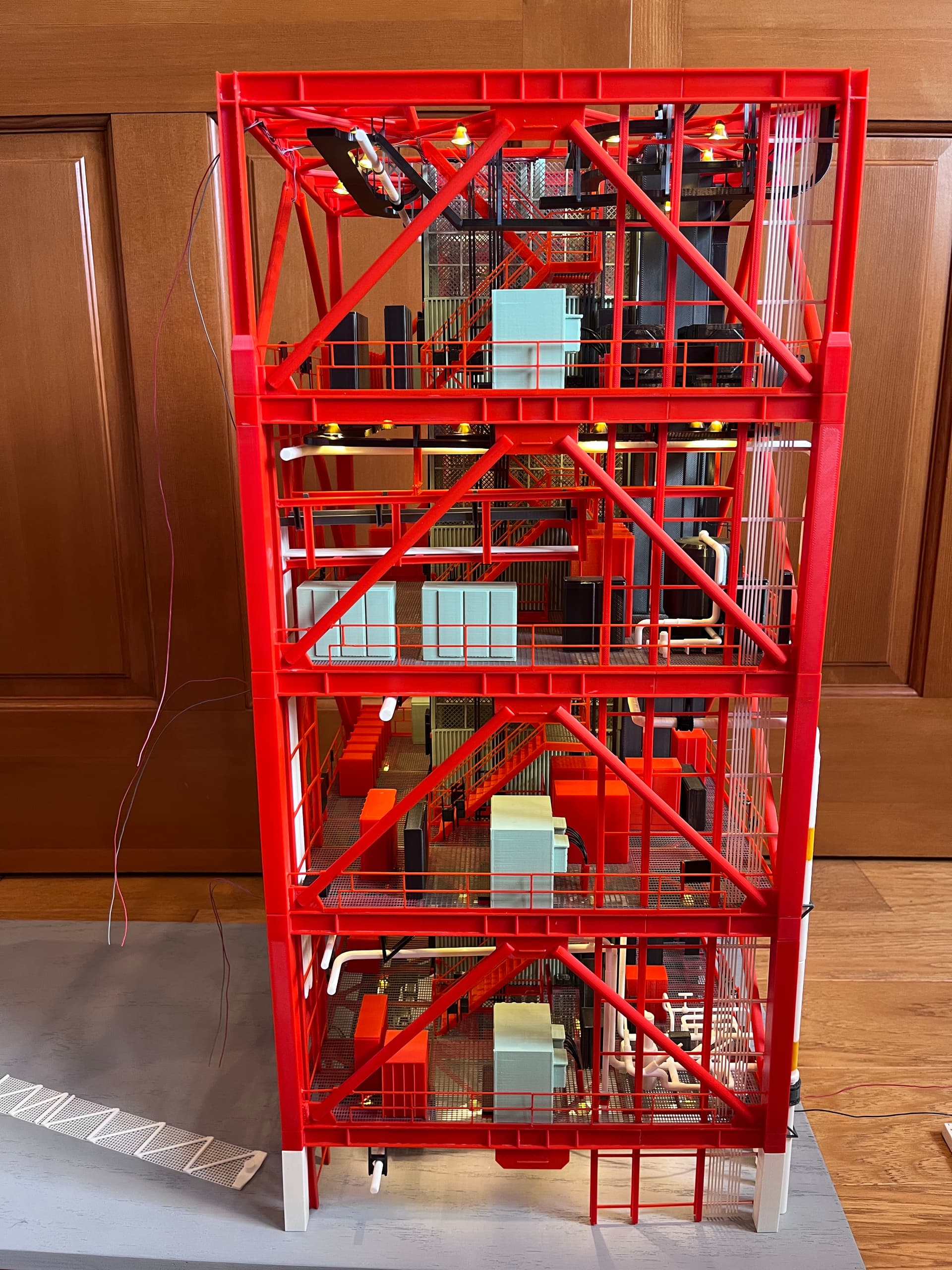
Finished adding the level 240 underfloor pipe, the large E3 pipe.
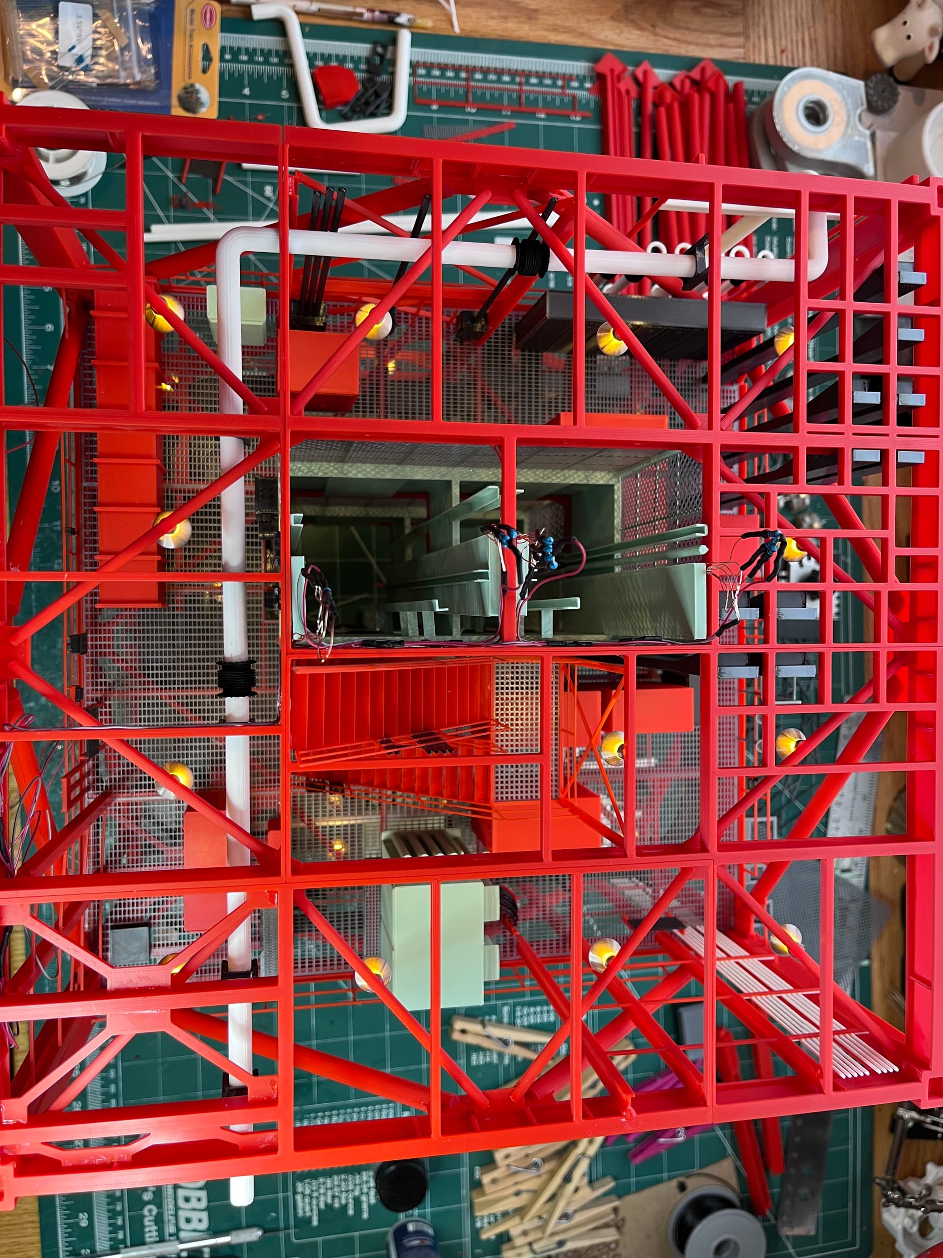
Also added side 1 racks that will hold more cables. You can also see that I have started adding the level 190-200 parts. These part have to be added with the tower on its side. Want to all of this added before going the next level up.
4 Likes
You still amaze me. The way you work is incredibly astounding. So much attention to every tiny detail makes it all look so very real and one can only expect an actual launch of the Saturn V or yet another Space Shuttle. Naturally all in 1/40 scale.
I wonder if we have astronauts in that size as well… Just kidding of course.
But all this really takes me back in time just like a rubber band and I always have to double blink to realize that this is just a model.
My goodness, I wished I had your skills and your patience in doing all this.
1 Like
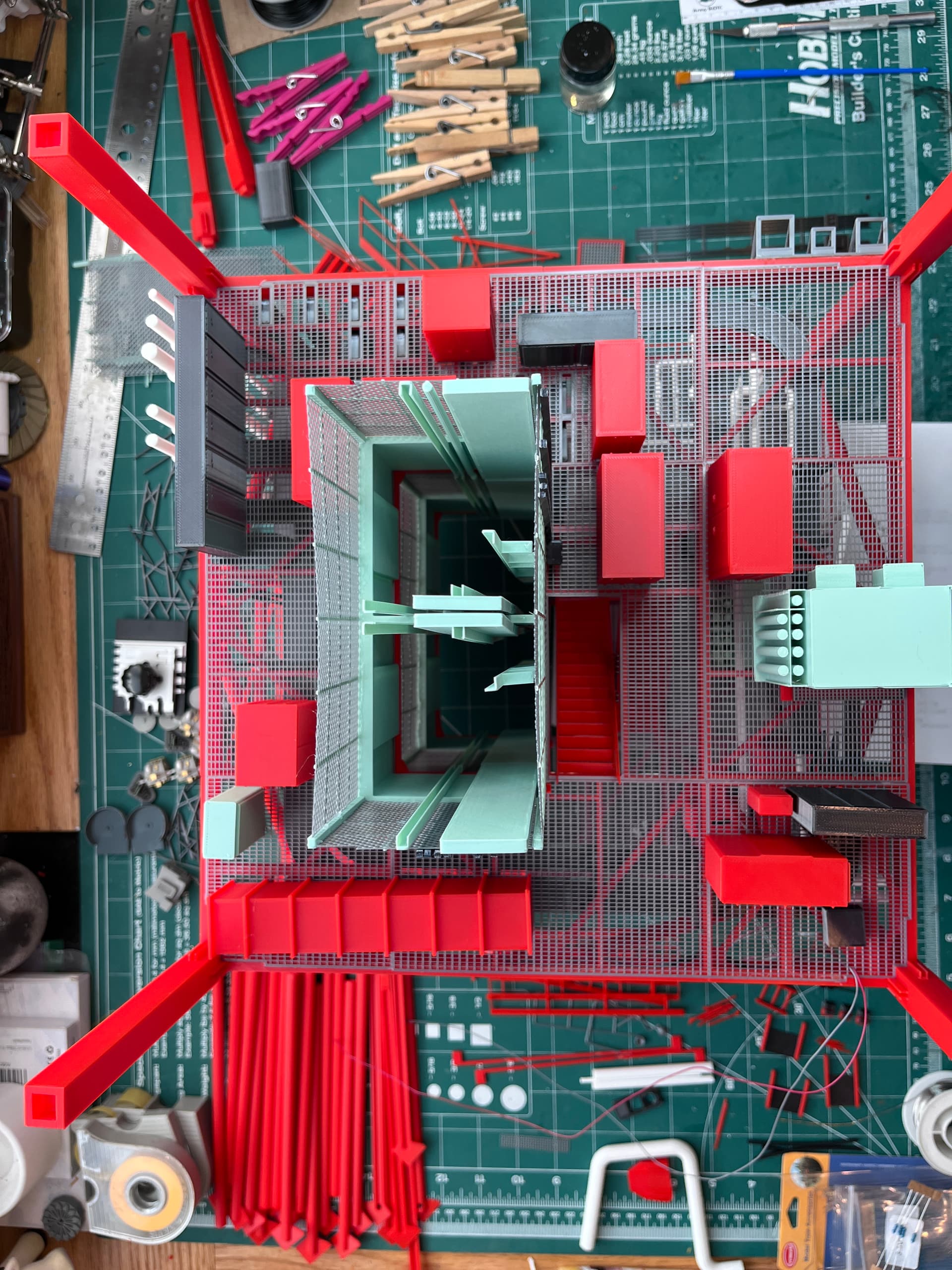
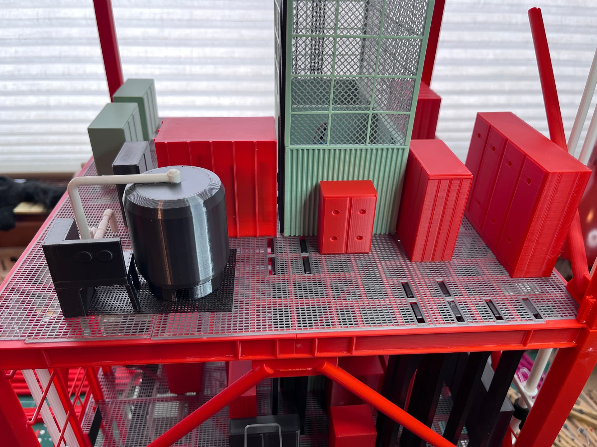
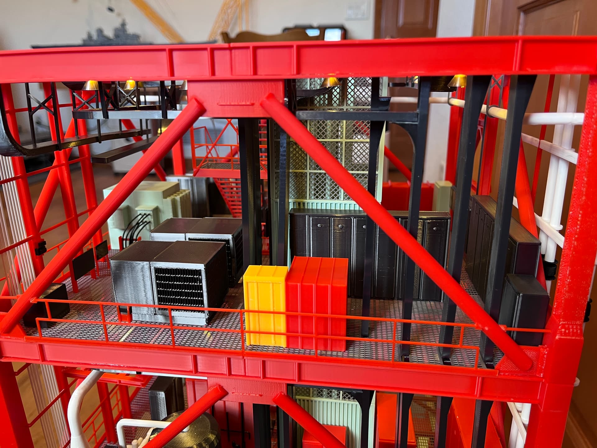
Starting to add the equipment to level 240. Most of these parts are scaled up from Aviator67 except the pipes. There is not much equipment on this level since there is no swing arm at this level. Given the extra space, here is where they added the toilet, a 3-holer. The LOX pipes ended two levels down, at the valves on level 200. The LH2 pipes continue up here to what the MicroArtwork is calling a “heat exchanger”. It is as far as the LH2 supply line goes, into the bottom of the vessel. The line out the top of the vessel is the top end of one of the LH2 vent lines. My chemical engineering degree tells me this is not a heat exchanger. A heat exchanger would require four pipes, an inlet and outlet for the two sides of the exchanger. They could be exchanging heat with the air if the vessel is not insulated, but given the heat and humidity in Florida and how cold hydrogen has to be to remain a liquid, this vessel would quickly become one huge ice flow. My guess is the stand/panel/device next to the vessel is probably sensing the level of the liquid and controlling pumps further down to ensure the liquid level is maintained so the lower fill lines always contain liquid LH2.
2 Likes
That is the Level 240 LH2 Heat Exchanger…
The level 180 LH2 Heat Exchanger looked like this…
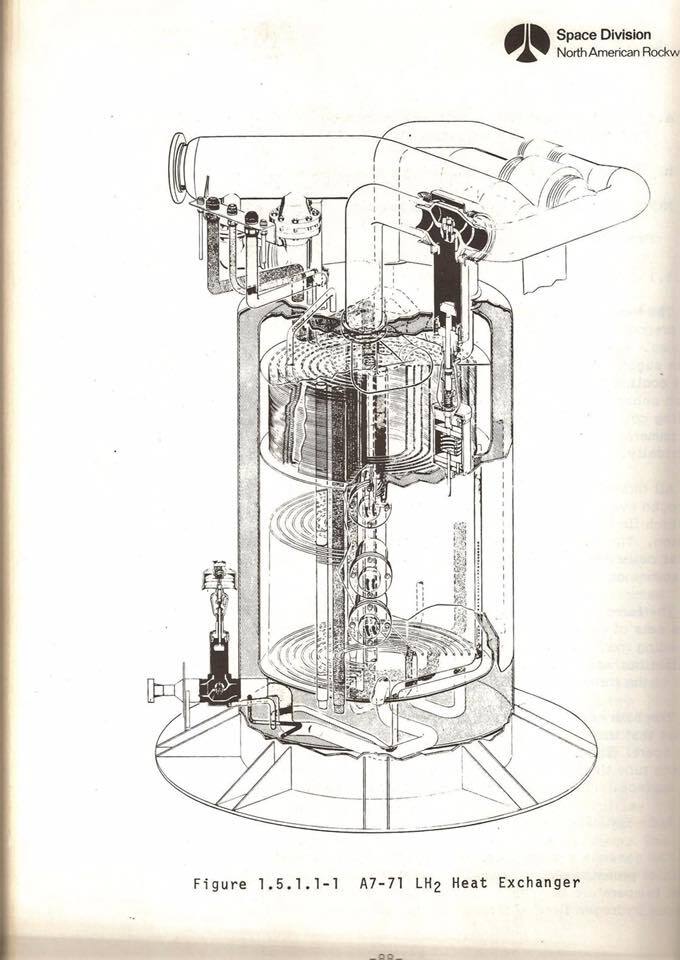
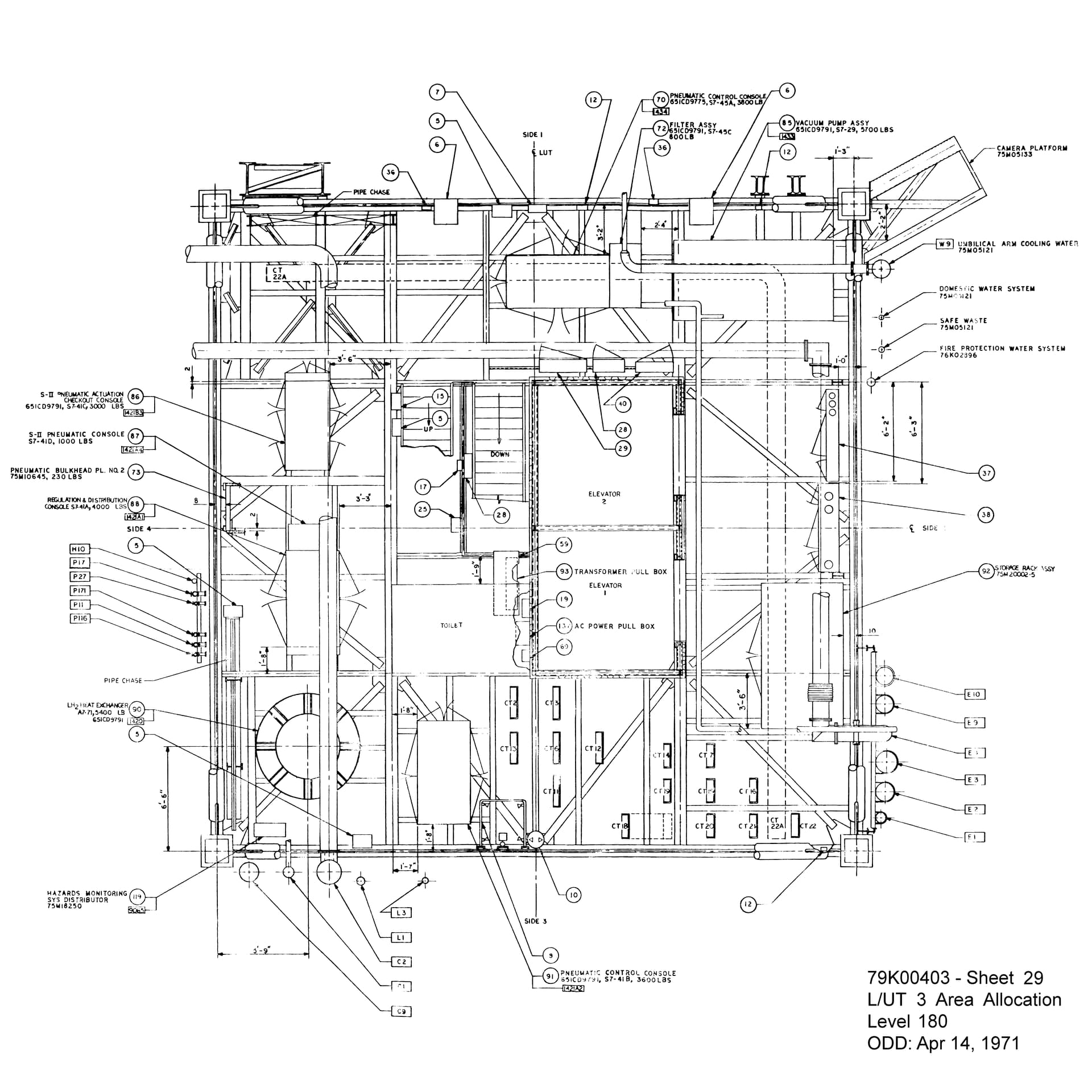
Much narrower and taller, you can see it here on print 79K-00403-29…
1 Like
OK, great. Thanks for the info. Do you have a picture of the level 240 heat exchanger? This one looks like it has three pipes going in the top and one out the bottom. That is what I would expect, 4 pipes.
Hey Bill, the only thing I have on the Level 240 equipment is the area allocation print…
79-00403-32…
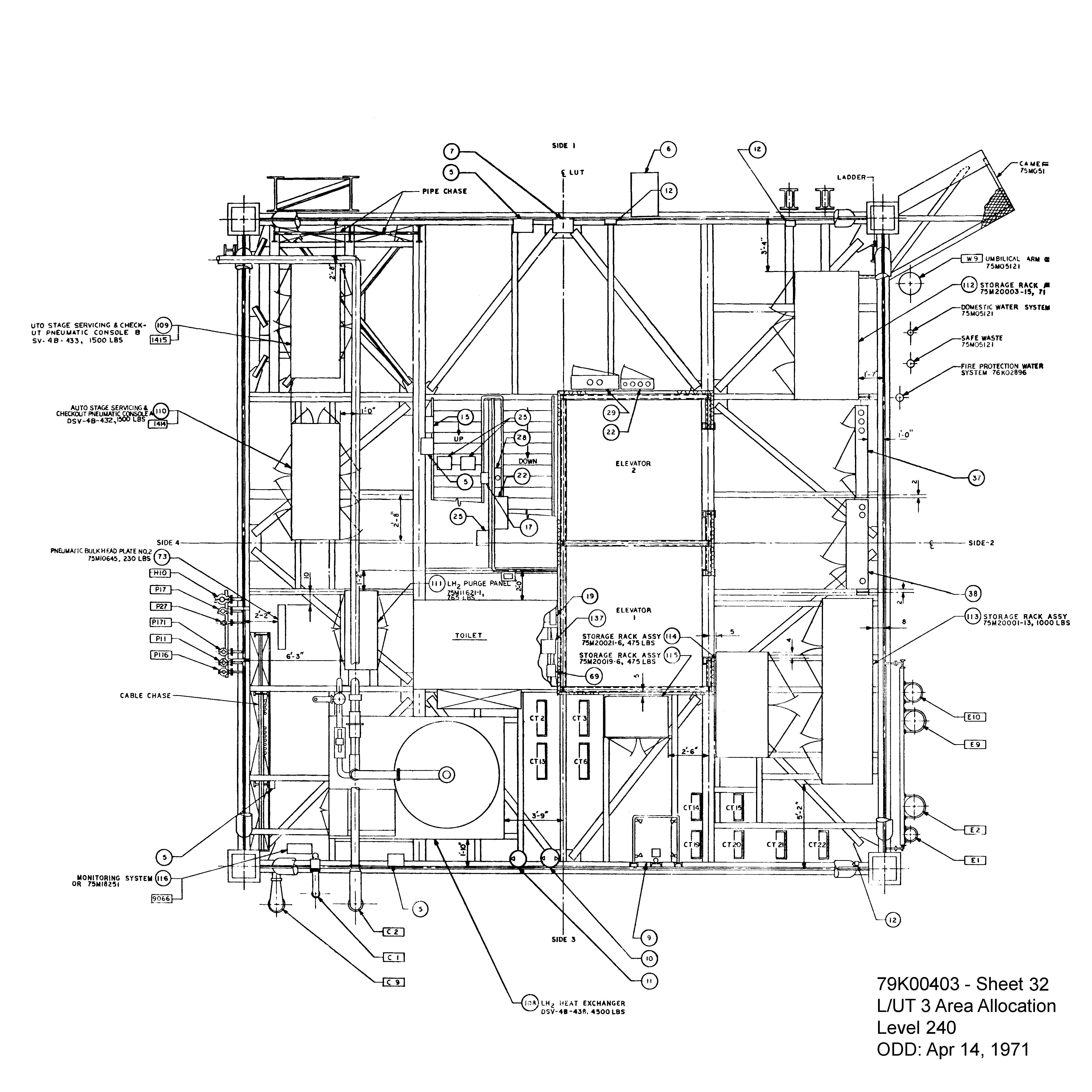
There are no direct pics of it available as far as I know…
Elmer
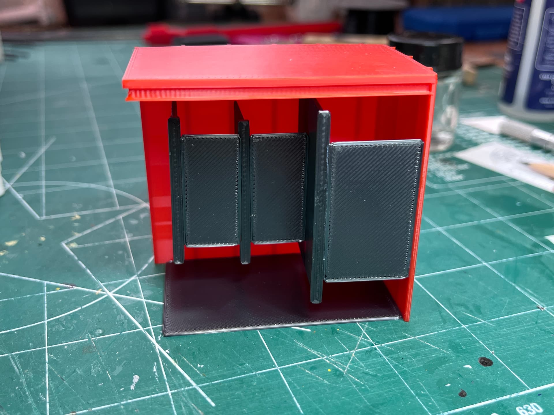
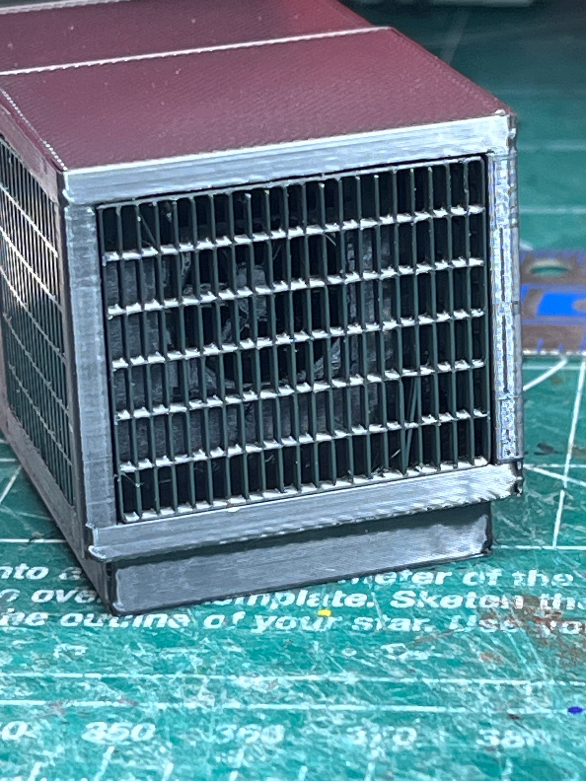
Thanks for looking that up for me. I will go with what I have. Here is the completed heat exchanger.
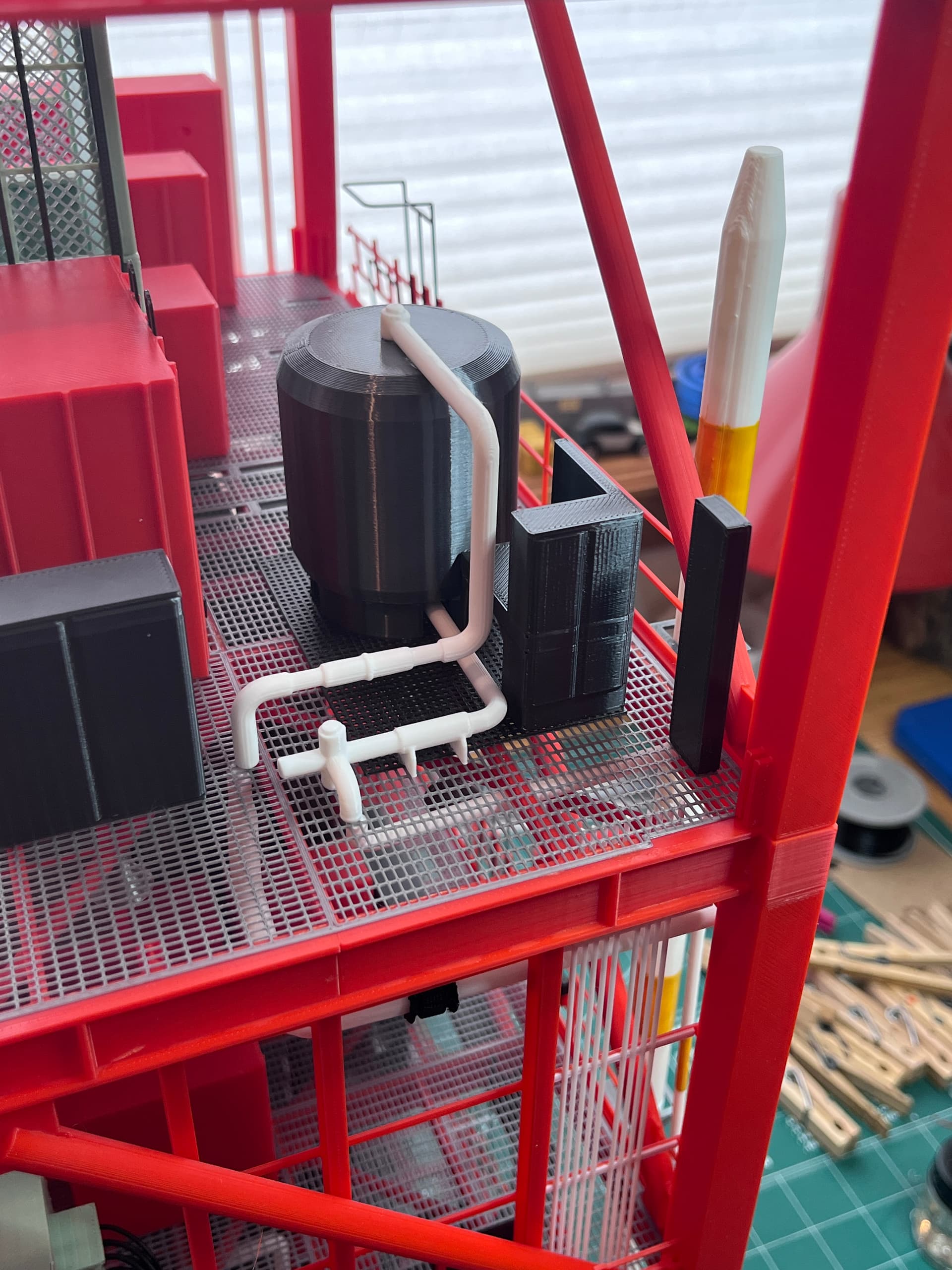
And the pipes on Side 3. I went ahead and painted the yellow stripes instead of trying to make those separate pieces printed in yellow.
2 Likes
After some discussion and research I believe the heat exchanger in question is exchanging heat between helium and hydrogen. The helium is used to maintain pressure in the massive tanks so they don’t collapse under pressure of launch and rapid depletion. It was also used to prevent pogo. As best I can tell, the helium entered the tower at ambient temperature and was cooled using the liquid hydrogen before entering the rocket. Since the helium was non-cryogenic, yet under high pressure, the pipes may have been relatively small and very thick walled. These pipes are probably too small to model, even at this scale. So on with the rest of the model…
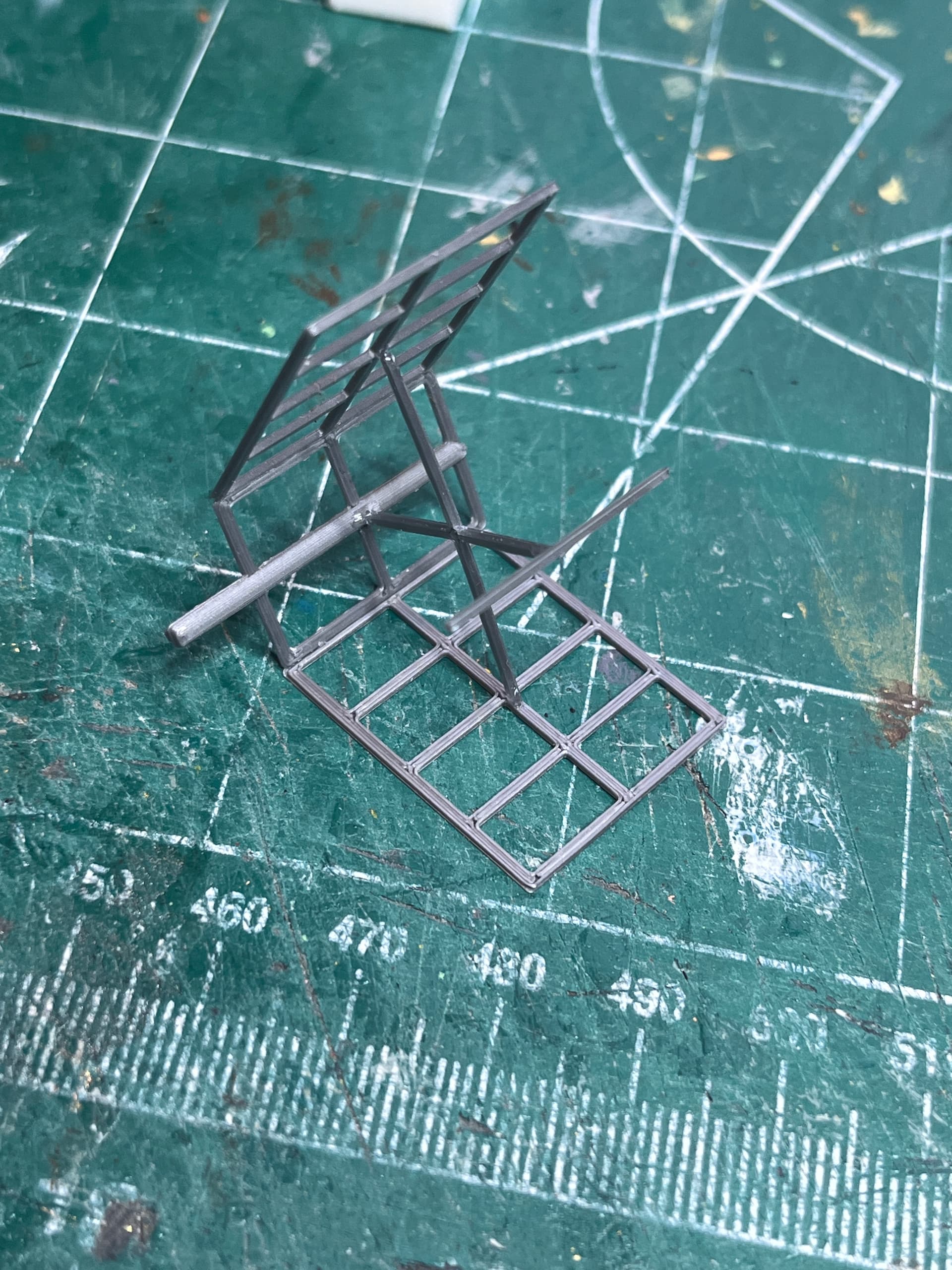
Level 240 to level 260 is complete. There is a rack called Level 252 that had to be fit before the main braces and railings were installed. Now on to the last level, level 260 which hold swing arm #7.

4 Likes
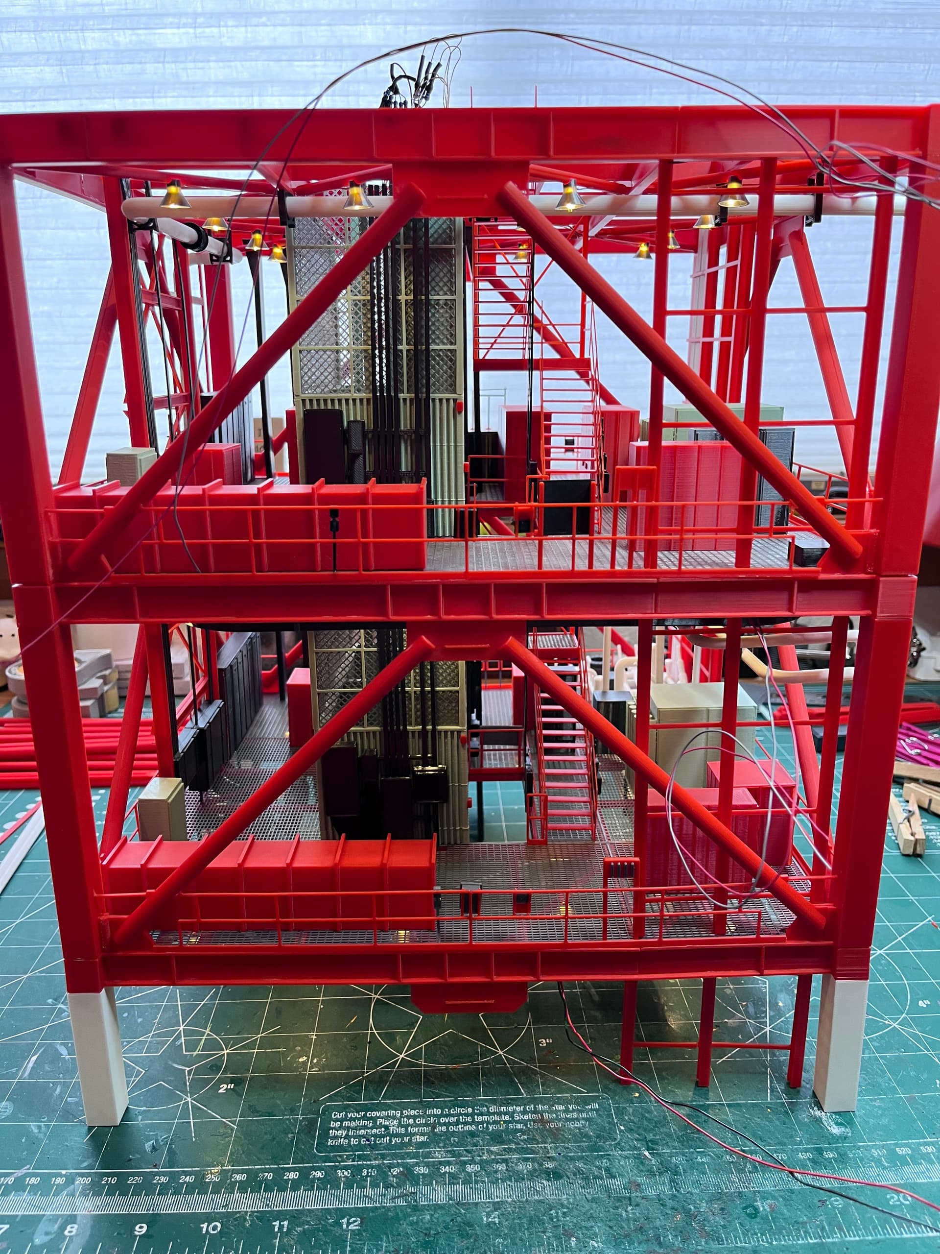
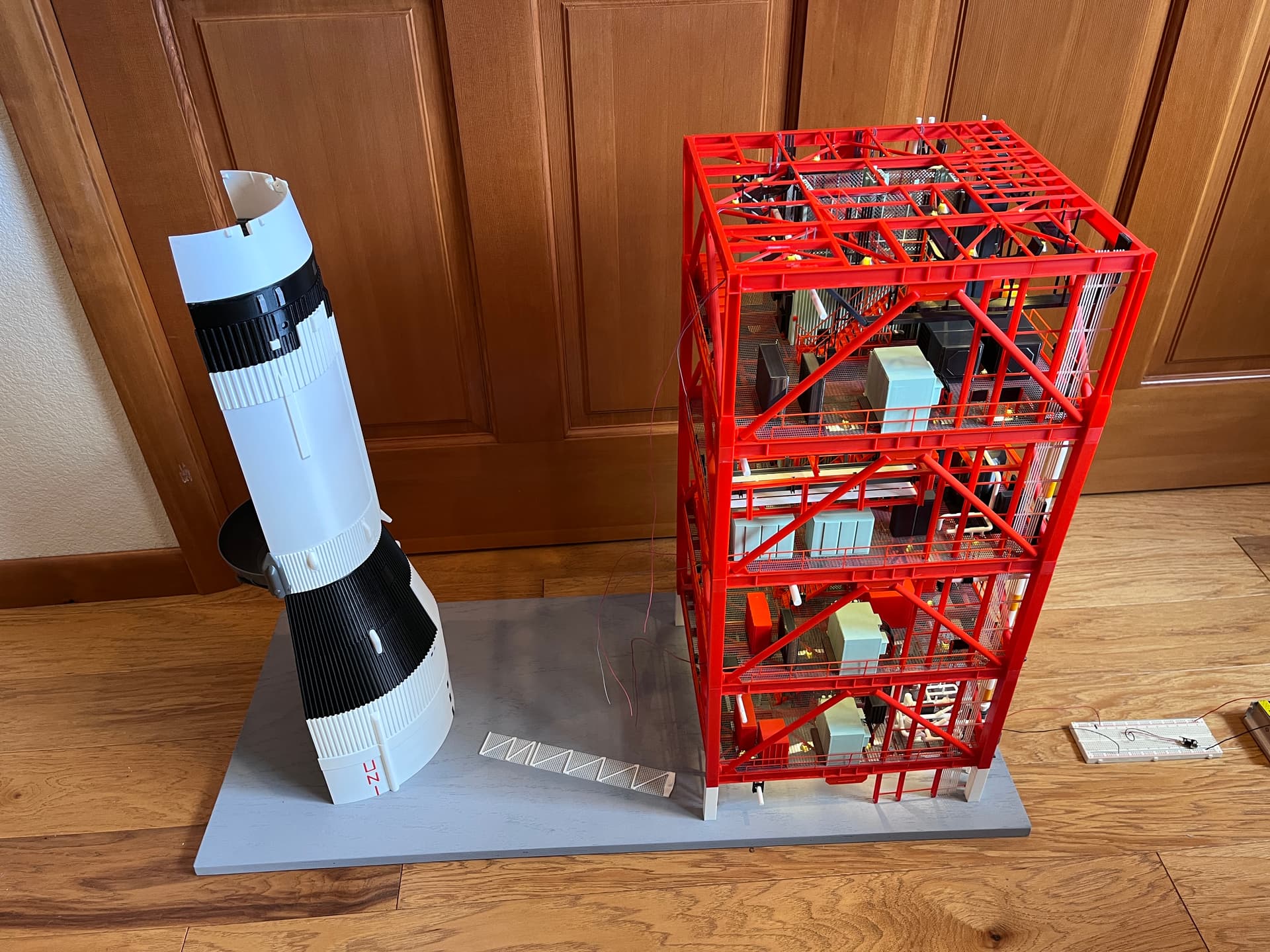
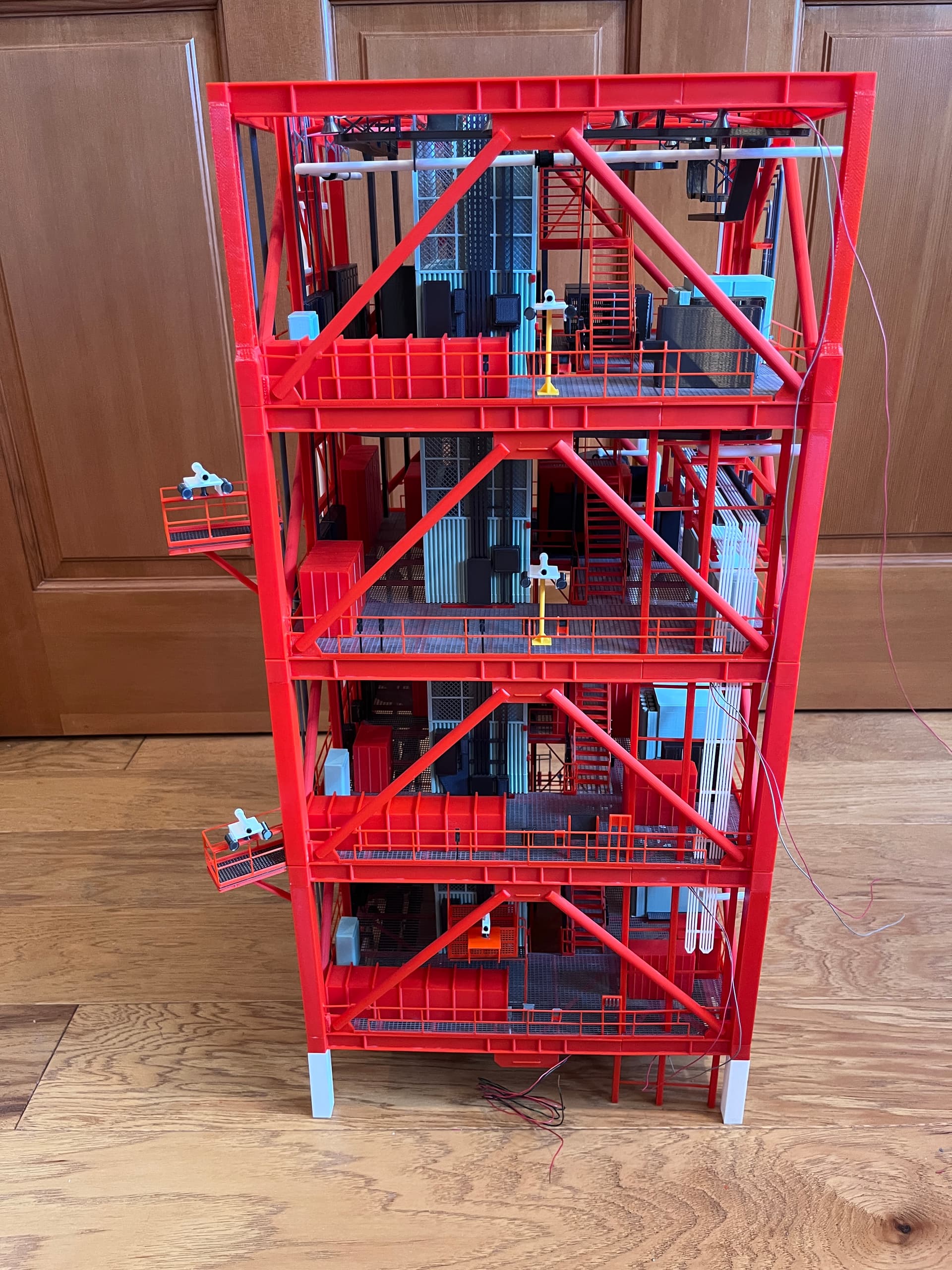
And this completes the core of the tower. I decided not to add grating to the top so you can see down into the upper level.
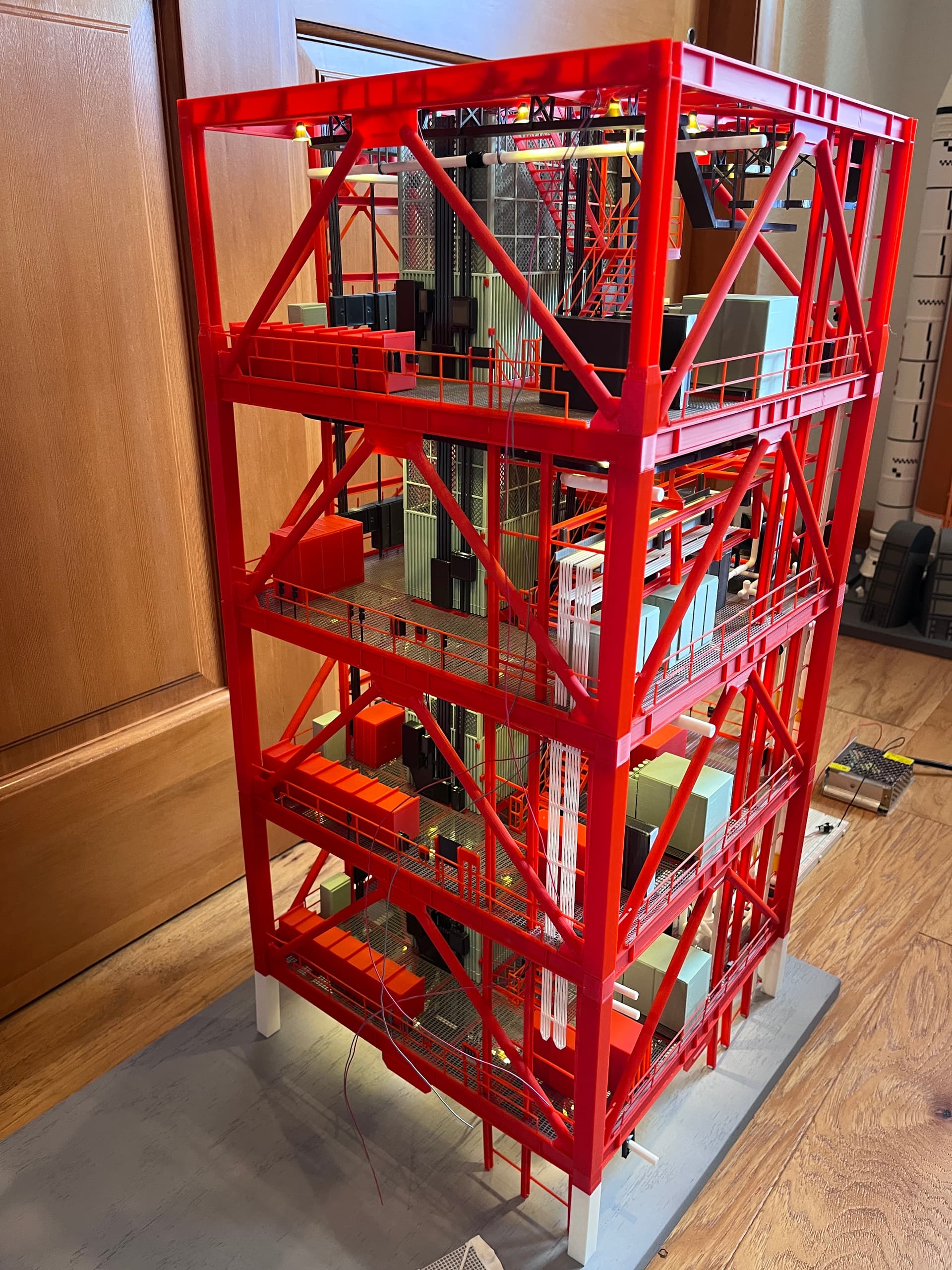
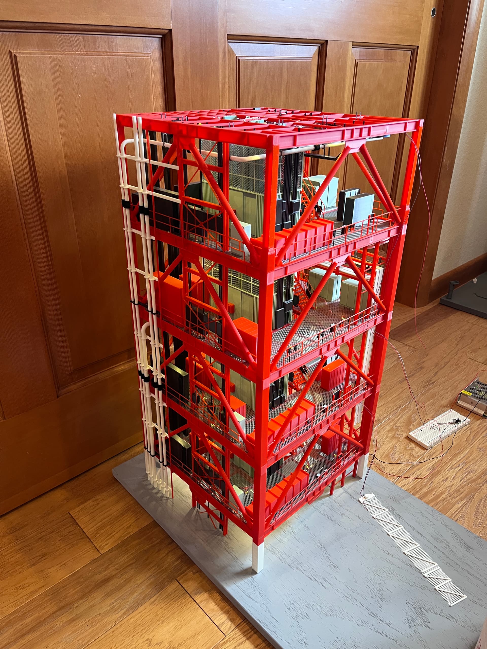
And here it is on the base board with the Saturn V section. Next up are all the pipes and platforms on the outside of the tower. You can see the wires that will go out the swing arms for those lights.
5 Likes
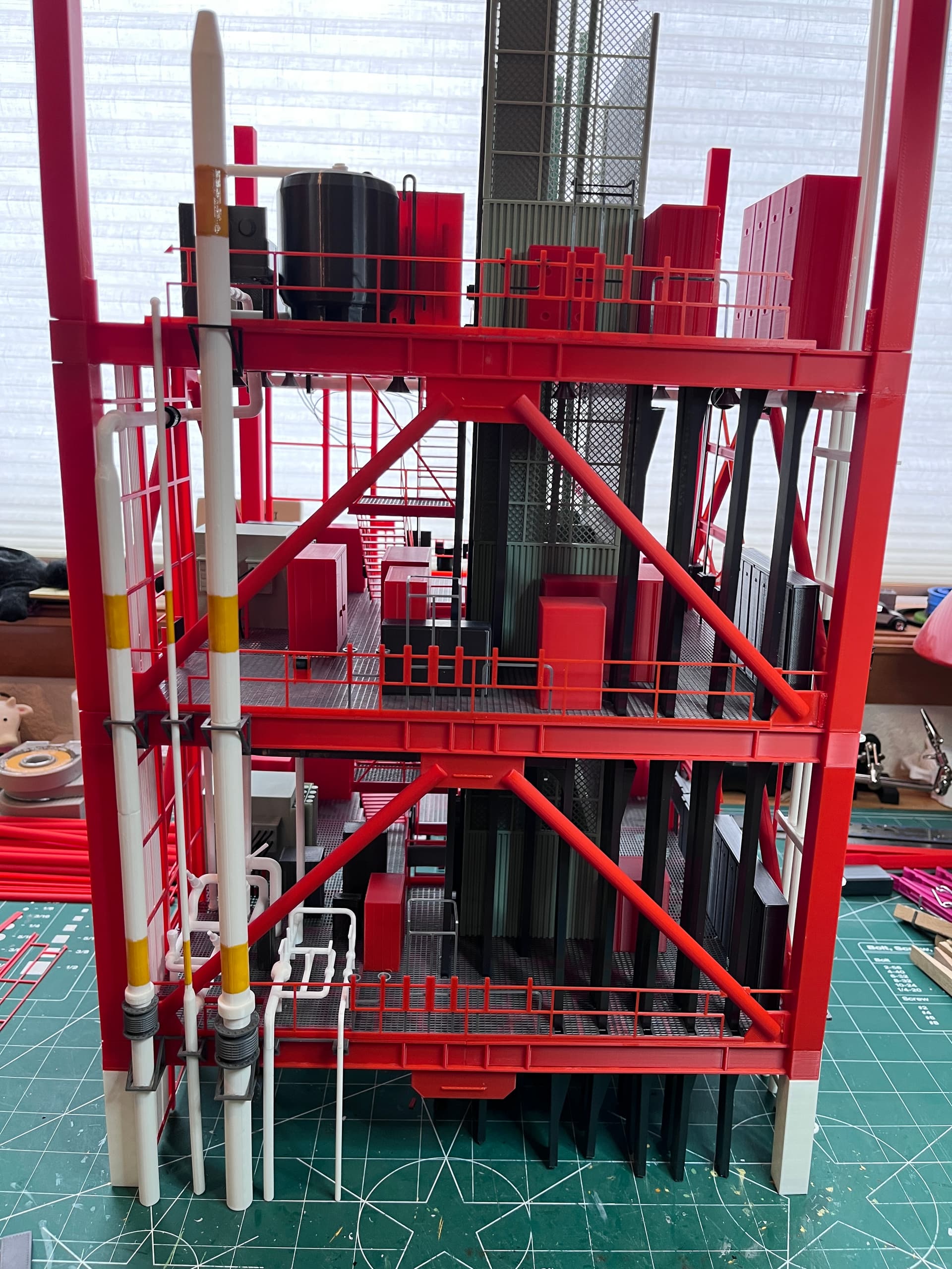
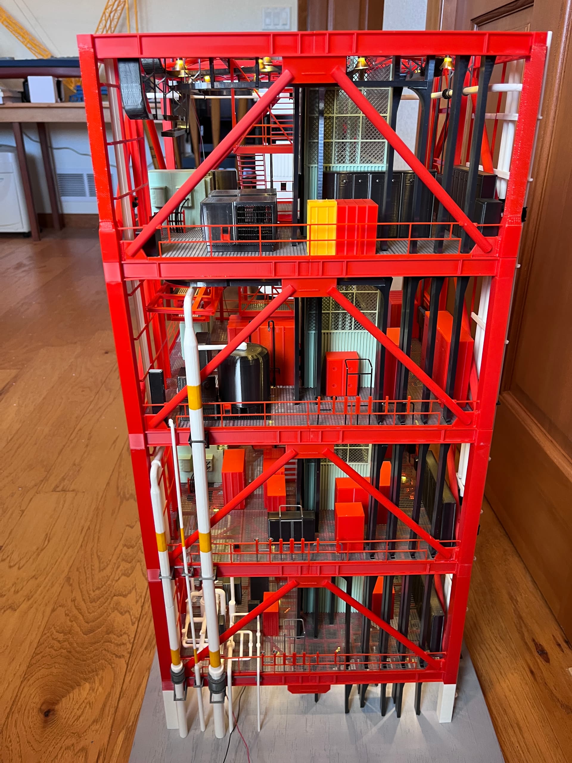
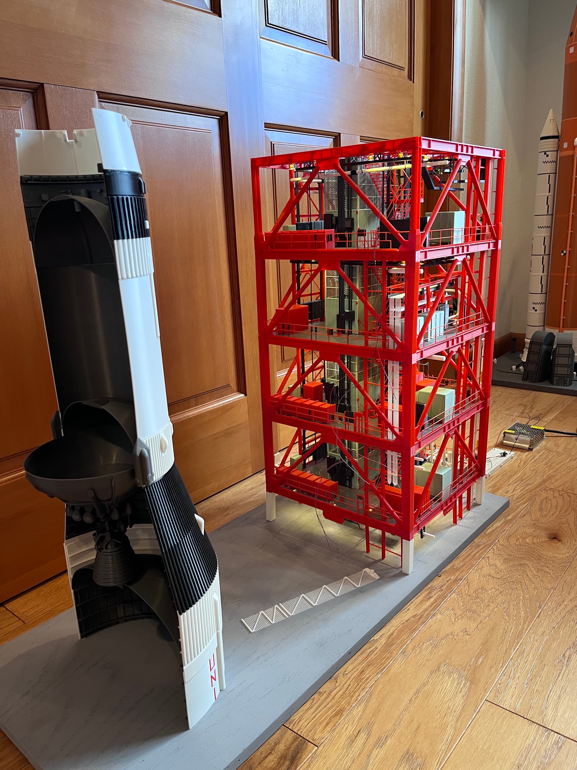
The outer sides are complete except for a few small parts and the swing arms/walkways. Here is side 3. There is a small platform at level 200 which is to access the anemometer antenna. I have not installed that yet because it will be too easy to break off. Here is the antenna.
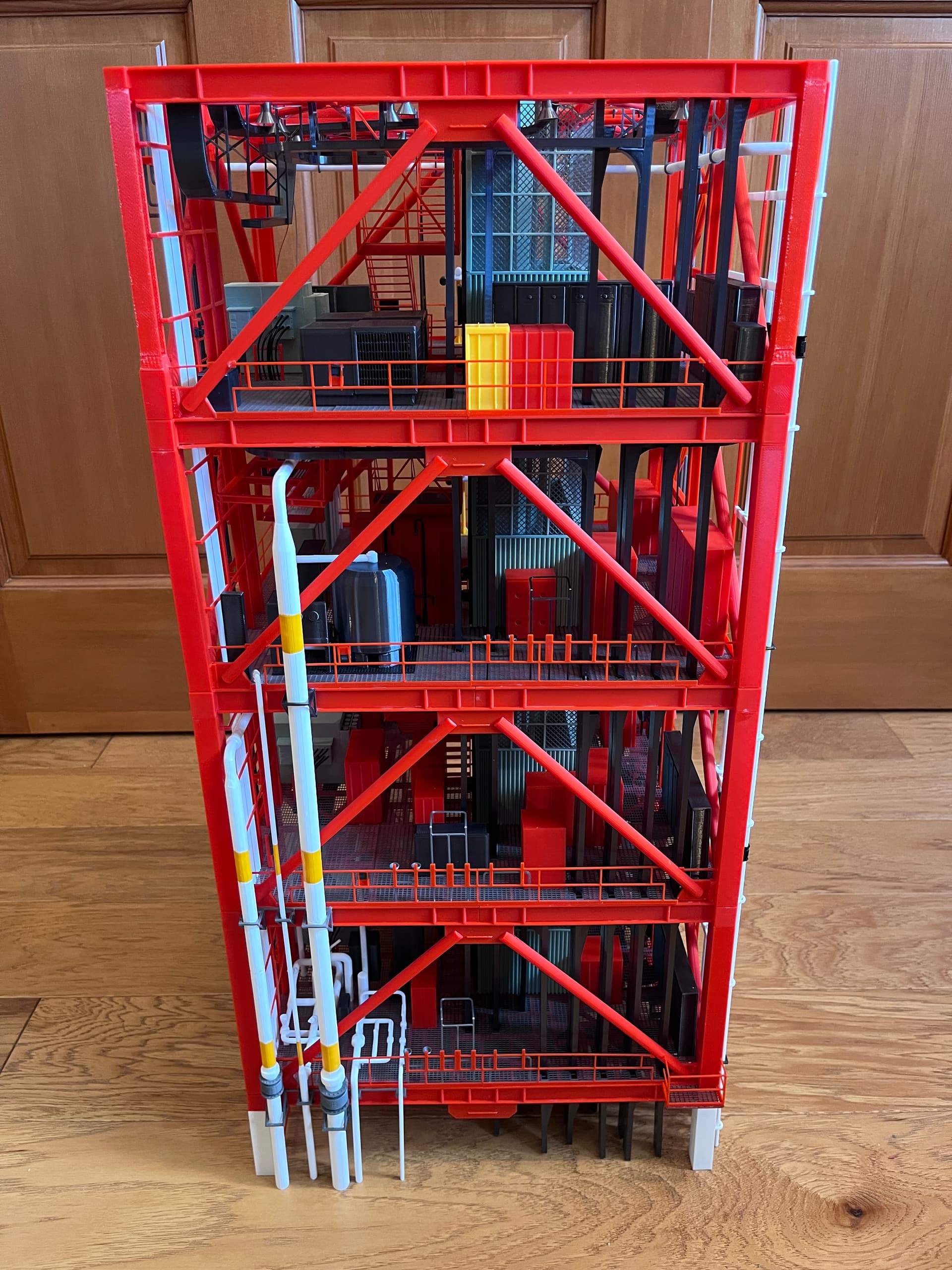
And here is side 2 with the water pipes. The largest one is for the fogging/cooling water that drenches side 1, the rocket side.
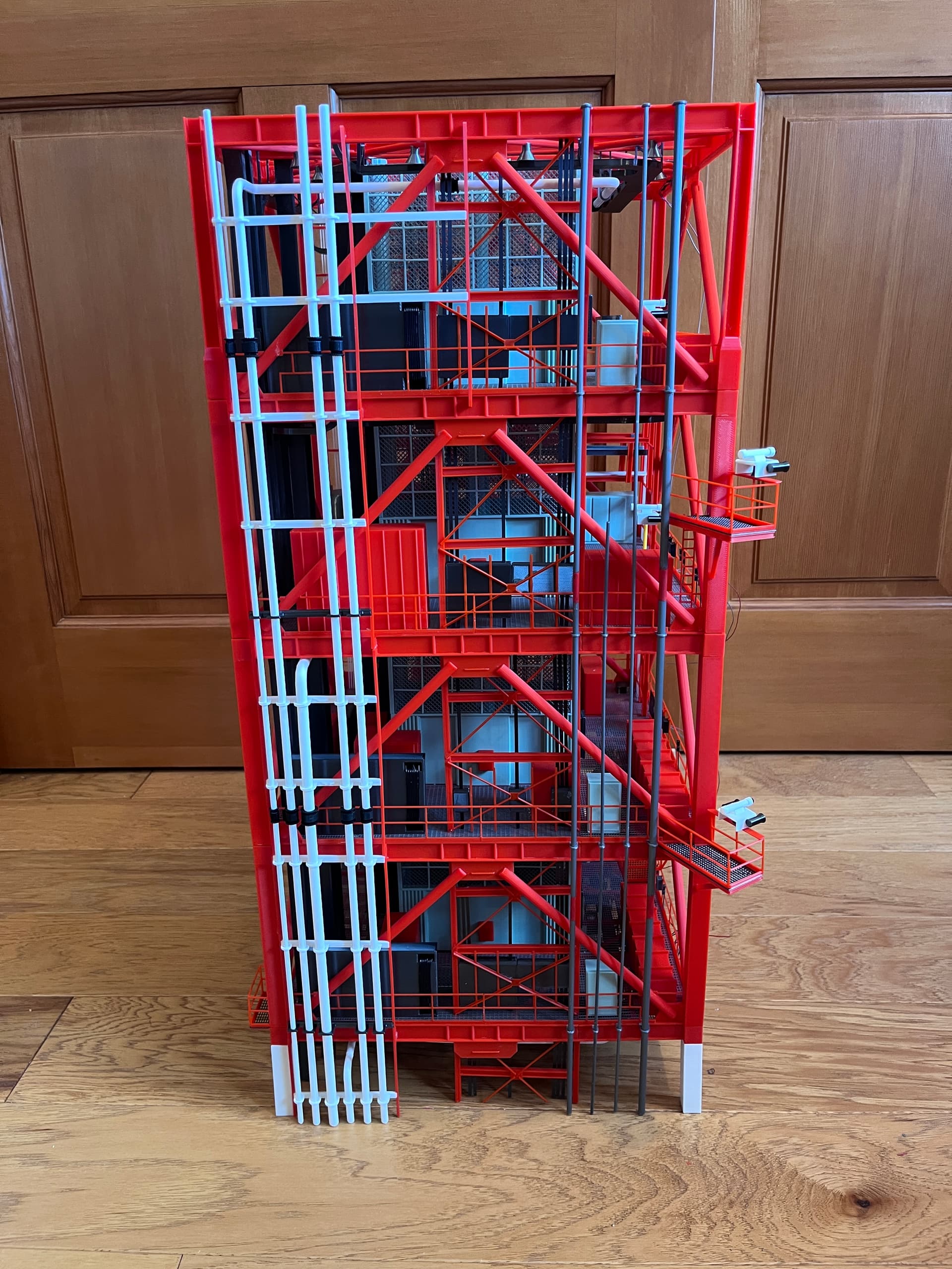
Here is side 4 with the various pipes. One is hydraulic fluid, the large one on the left that has pipes going to the big green boxes that help retract the swing arms. The other pipes are non-cryogenic gases such as helium, nitrogen and other gases used to fuel the rocket. This side still needs the swing arm walkways that wrap around to side 1.
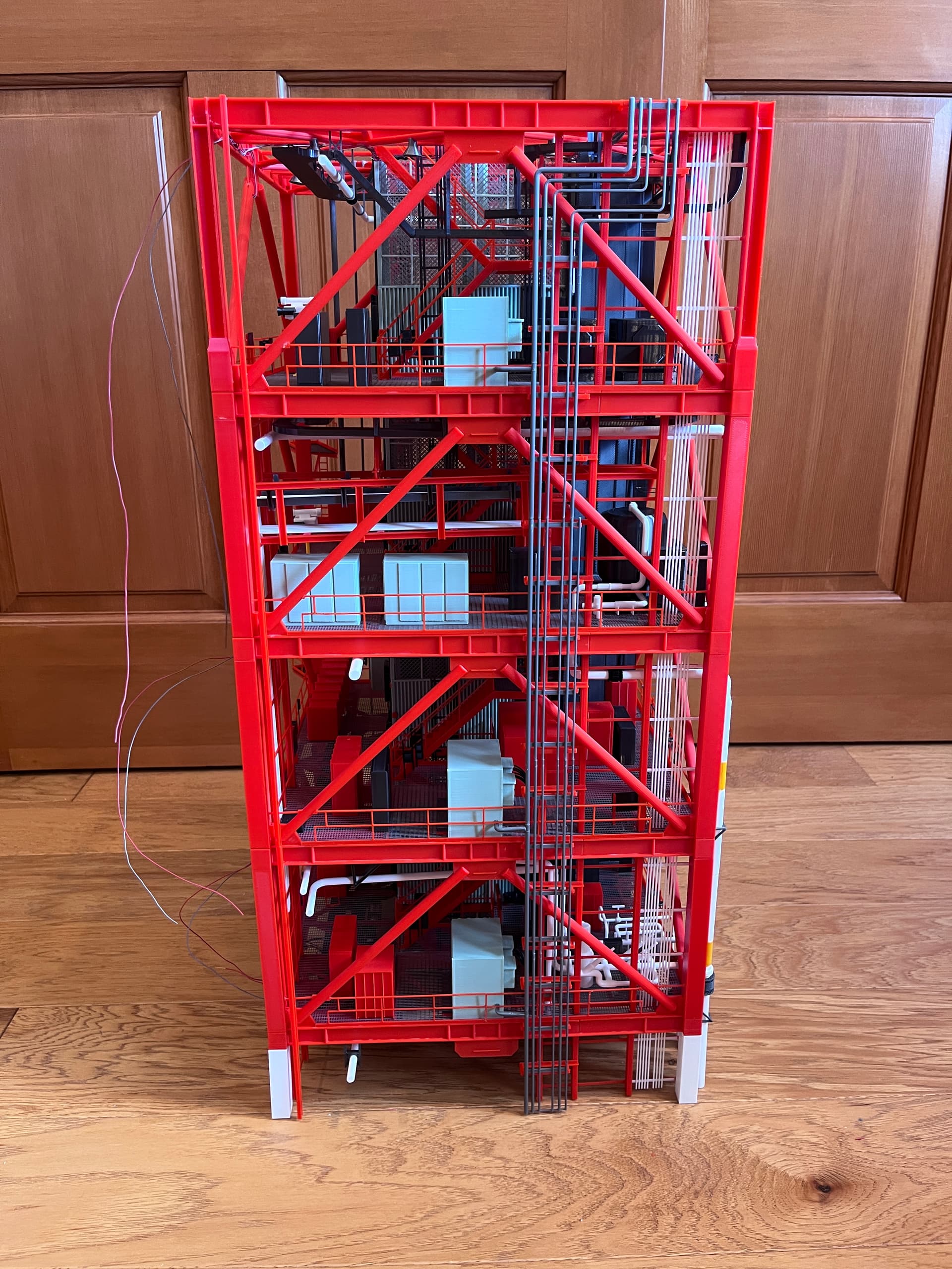
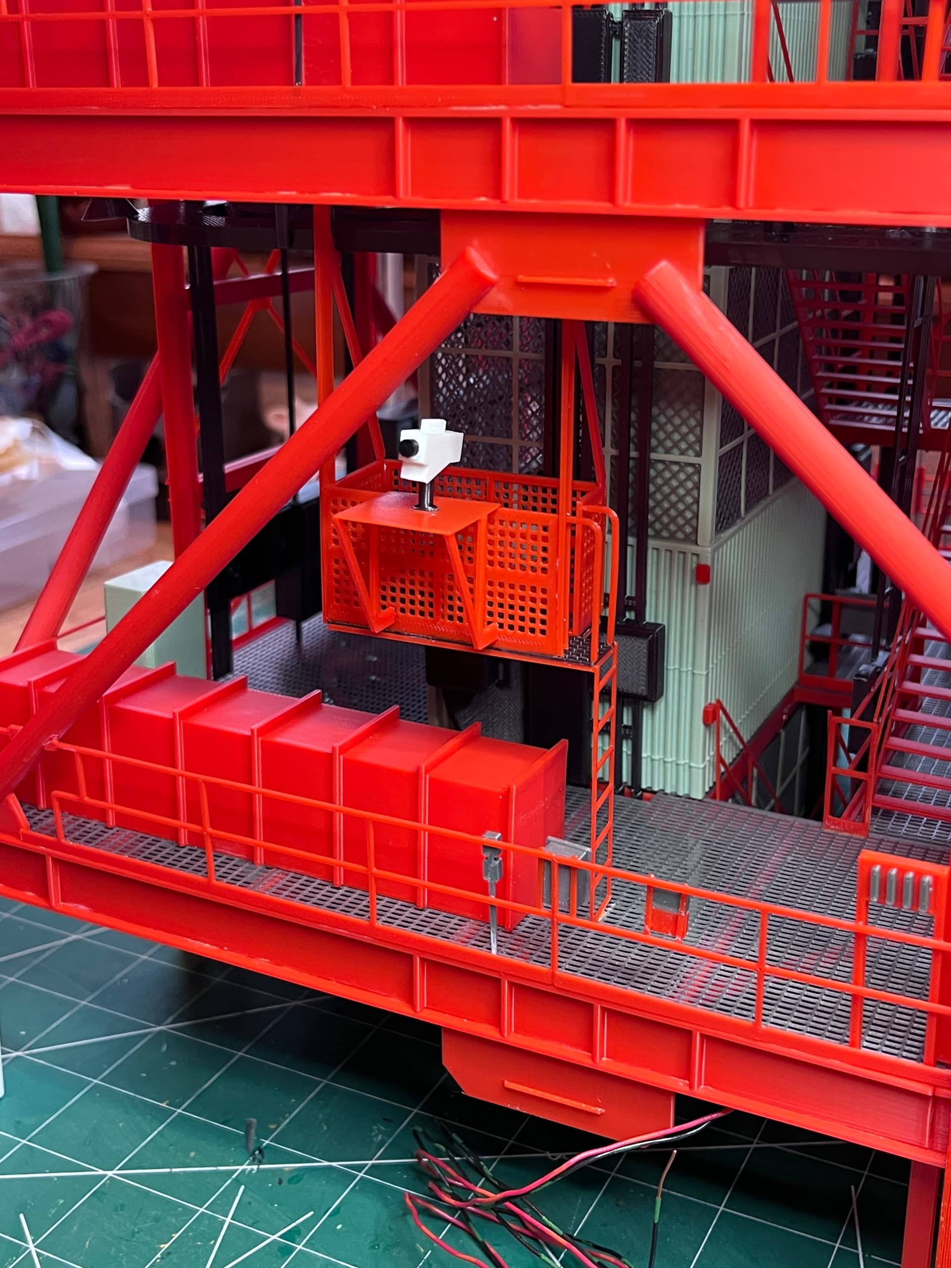
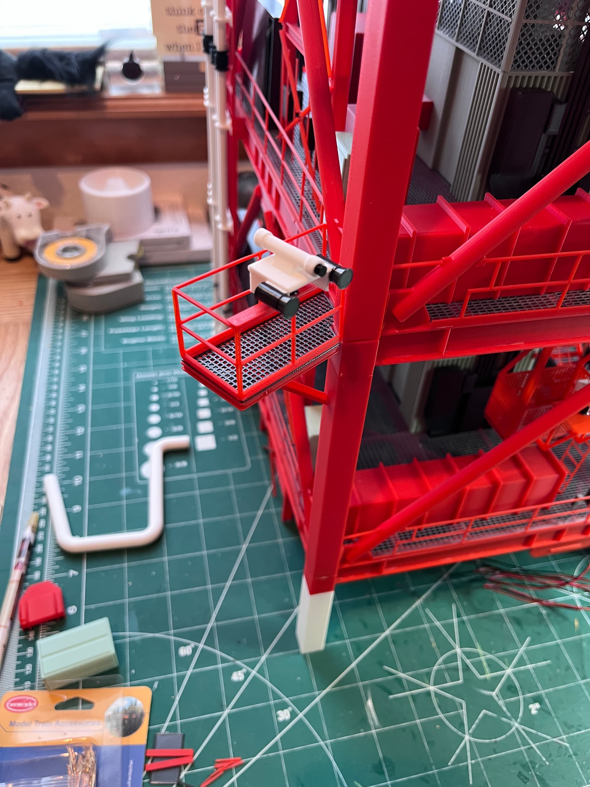
And finally side 1 which has many cameras installed. There is still quite a bit to add to side1. The next parts are the vertical I-beam structures that support the swing arms. Level 200 has a camera supported by a platform at level 210. The upper two levels have cameras on pedestals. Then there are side platforms supporting additional cameras.
4 Likes