Greetings everybody! For Christmas this year, I am making a model display of all of the aircraft my dad flew in route to 3,500 hours flying for the Air Force. I thought that some of you might find it interesting, so I decided to post this “Work in Progress”. It is a little different than the other WIP’s I have seen on this site. The planes he remembers flying include the following:
T-28 “Trojan”
T-34 “Mentor”
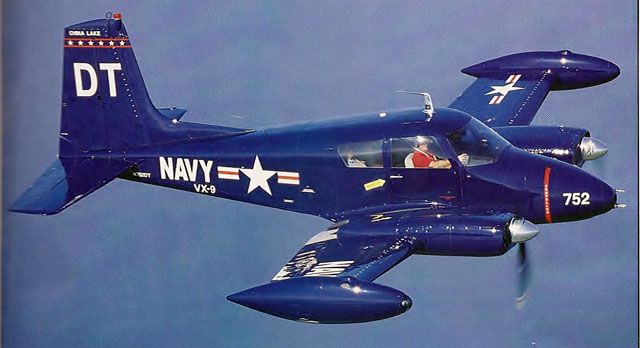
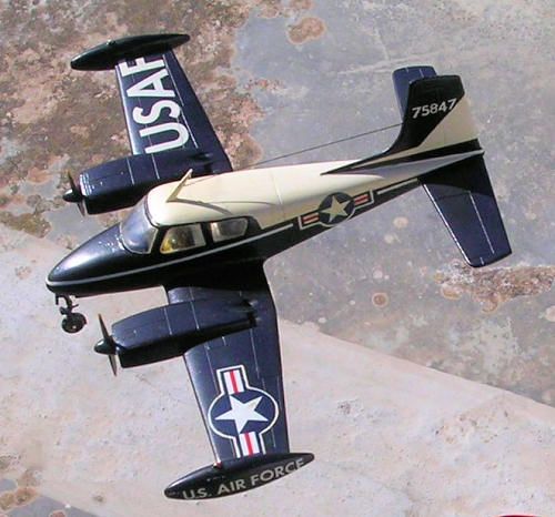
U-3A “Blue Canoe”
B-25 “Mitchell” (as flight instructor)
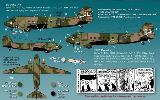
AC-47 “Puff” (AKA “Spooky” in Vietnam in 1966)
T-29 “Flying Classroom” (flying Air Force Academy Cadets)
He flew other aircraft, but he has Alzheimer’s and can no longer recall which ones they were.
The airplane models in the display were all created in AutoCad Civil 3D using plans of varying quality. The plans of the planes were obtained through Google searches on the Internet. For some planes there were multiple options complete with 3-views and sections, for others, the pickings were slim. The T-28 Trojan was one of the planes for which multiple plan sheets were available. The image below shows the AutoCad drawing for the T-28, complete with the scaled plan sheets, all of my construction lines and sub-assemblies, and the model.

The first thing I did was scan the plan sheets, import them into AutoCad and scale them to 1/350 scale. With that accomplished, the next thing I did was make the fuselage. I did this by tracing the available cross-sections and creating closed polylines, as seen in the image below, showing a portion of my T-28 drawing.

The polyline cross-sections were then copied into position on the profile portion of the drawing. These cross-sections were subsequently rotated 90o about the vertical axis. The LOFT command was used to create a solid model of the fuselage from the cross-sections. Note that for the T-28, I traced the cockpit canopy as separate polylines that I lofted distinctly from the fuselage cross-sections.
Cross-sections were not available for the wings and stabilizers. I therefore had to create my own. For the wings and horizontal stabilizers I used a typical foil cross-section (blue foil in first image) that I scaled so that the length of the foil matched the width of the wing or stabilizer at the section location. This process involved a lot of copying, scaling and rotating to get the cross-sections located, oriented and sized properly. During all of this process, symmetry was my friend because the wings and horizontal stabilizers only had to be done once. Then, I could use the MIRROR command to make a mirror image for the other side.
For the vertical stabilizers I created a symmetric polyline using 0.02” diameter circles, arcs and lines that I trimmed and joined (magenta foil in the first image). The maximum width of the vertical stabilizer was 0.04”. Unlike the wings and horizontal stabilizer, the vertical stabilizer did not increase in width as the length increased. So, rather than copy and scale the cross-sections, I copied the ends to the opposing edges of the stabilizer as shown on the plans, connected them with lines, then joined the lines and section parts together to form a closed polyline, which could then be rotated as needed and used in the LOFT command to create a solid model.
The procedure I used to make the vertical stabilizers varied slightly among the aircraft but was similar to the procedure used for the T-28 described here. The procedure used to make the wings and horizontal stabilizers was essentially identical to the procedure described here for all of the aircraft.
After the wings and stabilizers had been made, the next thing I had to do was position them and orient them properly with respect to the fuselage. How this was done was similar for every model, but varied somewhat depending on how the plans were laid out. For the T-28, and most of the other planes, the sectioning was done along the side view elevation of the aircraft, but for a couple of planes the sectioning was done on the plan view. In all cases, I used reference lines on the drawings for copying and moving objects from view to view
Several of the aircraft, including the T-28 had sloped wings. At the bottom of the first image above you can see the polyline (magenta) that I created of the wing, which slopes up from horizontal. This polyline was copied up to the wing assembly (yellow) and rotated about two axes for proper alignment. The wing, which was constructed flat, was then rotated up using this angle for reference. With everything in the proper position, the UNION command was used to join the fuselage, wings and stabilizers together as one piece.
With the basic airplane models made, I turned my attention to detailing. At 1/350 scale, you are somewhat limited to the level of detailing that you can add by the limitations of the 3D printer used to transform the CAD “virtual” model to a solid, tangible model. What exactly those limitations are, I do not know, because I am only just learning and do not have enough experience at this point.
Nevertheless, I wanted to add some detailing to highlight some features such as the canopy, ailerons, flaps, elevators and rudders. To do this I traced the outlines of the features on the plans and used the PROJECTGEOMETRY command to project the lines onto the solid model. I then used both the LOFT and EXTRUDE commands on 0.004” radius circles oriented perpendicular to the projected lines to create what essentially amount to long solid tubes along these projected lines. Since projected lines are on the surface this meant that half of the tube was beneath the surface and half protruded from it.
To make the canopies I used the UNION command to join the tubes to the model creating half tubes protruding from the surface. For the control features I used the SUBTRACT command to etch half tubes into the surface. When I did the detailing and at the time of this writing I have no idea how well this method will work, but it looks pretty good on the virtual models, as may be seen on the U-3A “”Blue Canoe” and B-25 “Mitchell” AutoCad models shown below.


The image below, shows the mid-aft section of the AC-47 “Puff”. All of the other models are solid, but I hollowed out the inside of Puff because I thought it would be cool to add the mini-guns on the inside. Fortunately, I found some really good pictures to assist in the process and was able to make a decent replica of the real deal. I decided not to add barrels because at 0.02” diameter, they would print, but would likely be too fragile to withstand the handling required in cleaning and shipping. I did however, drill holes to accommodate whatever material I find suitable to use as barrels. The same may be said for the guns on the B-25. Note that I also added the rear landing gear, even though it is pretty small and might not survive the shipping and handling.

To this point, I did not know what I was going to do about the propellers. At this scale, I was afraid that even though they would print they wouldn’t be strong enough to withstand handling and would break before I even received them, or when I was painting the models. Still, even though I knew that there is an art to propeller design and propellers are as individual as the aircraft they are on, and that there was no way I was going to be able to make them 100% accurately, I thought that I could make something that would look good, so I decided to go ahead and try making them.
Of the six aircraft two (T-28 and T-34) are single engine and four (AC-47, B-25, T-29 and U-3A) are twin engine, but that doesn’t really matter for designing the propellers. Two of the aircraft (T-34 and U-3A) have two bladed propellers and four (AC-47, B-25, T-28 and T-29) have three bladed propellers. This is marginally important in the design, but the most important factor is the shape of the individual blades. Although, the blades are all different they basically fall into two categories that I will call tapered blades and fan blades. The Tapered blades taper at the ends to a smaller point, whereas the fan blades are of uniform thickness to the end. Four of the aircraft (AC-47, B-25, T-34 and U-3A) have tapered blades and two of them (T-28 and T-29) have fan blades.
The image below shows the plans I used to generate the two types of propellers with the tapered blade being on the left and the fan blade on the right. With a single blade designed for each blade type, I could ROTATE/COPY the blade once 180o to make a two bladed propeller, or twice 120o to make a three bladed one. At this point it was simply a matter of scaling the propellers for the particular aircraft.

Suspecting that the propeller might not print too well I decided to make ”spinning” versions by creating disks instead of individual blades.

At this point I sent all six aircraft and the two propeller versions for the T-28 to 3Delivered (also known as Click2Detail). The spinning option was appealing because I had considered the possibility of displaying the planes in flight from the start, and spinning blades seemed more appropriate.
A short time later, I received an e-mail from Thomas of 3Delivered saying that the single propellers would be too fragile and that they needed to be supported inside rings for printing. He also advised me that they could print using a clear material, which made the idea of spinning propellers even more appealing. Shortly after that, I received another e-mail saying that the clear spinning propeller came out great, so I sent the spinners for the remaining aircraft. 3-Views of all six Autocad models, complete with spinning propellers are shown below.

While waiting for the planes to be printed, I turned my attention to how I was going to display them. From the outset, I envisioned the 6 aircraft being arranged together on a wooden plaque of some fashion. Because of the different sizes of the aircraft, I was thinking that I would need an oval shaped plaque. A trip to our local Michael’s was a complete success, as I found the perfect plaque for the display. It is oval shaped, but more ornately carved along the edges than a simple oval. More importantly, at 9” x 12”, it is the perfect size for what I had in mind, and to top it off, it was only $6.48. The image below shows a scan of the plaque.

I copied the scan of the plaque into AutoCad, scaled it to size and traced the outline of it. I used this outline to make a virtual model of it. This allowed me to try different layouts. The image below shows the design I decided to go with.

Initially, I was uncertain if I was going to mount the aircraft on the surface of the plaque, as if they were on the ground, or suspend them by some means, as if they were in flight. Looking down on it in plan view, however, it didn’t matter; I could still lay out the relative positioning of the planes and the brass plaques for the title and plane names. (I also later included a small plaque at the bottom that reads “Scale: 1/350” that is not shown.) Because of the relative sizes of the aircraft, there was a lot of visual dead space between the large planes at the top of the plaque, so I decided to add a couple of Air Force insignia to fill the space.
With Thomas saying that the clear propellers came out good, combined with the fact that if I displayed the planes in-flight I wouldn’t have to deal with the landing gear, and I thought it would look cool, I decided to display the aircraft in-flight rather than on the ground. The image below shows the AutoCad model display at an oblique angle. You can see that the aircraft are at different levels; the T-34 at the front is 1-1/2” above the surface, the T-28 and U-3A are 2” high, the B-25 and AC-47 are 2-1/2” high, and the T-29 is 3” high. To suspend the aircraft in these positions I will use 1/16” diameter brass rod, and although I forgot to mention it previously, I “drilled” 0.063” diameter holes in the underbellies of all of the models to accommodate the brass rods.

Another thing I did while waiting for the planes to be printed was design the decals for the planes.
Originally I intended to make my own decals and print them myself, as I have done in the past. Unfortunately though, both the U-3A and the AC-47 require white decals, and it has been my experience that decals printed on white paper do not look as good as ones printed on clear paper, at least at 1/350 scale. My next thought was to just buy some decals, and so I got on-line and ordered Gold Medal Models’ “1/350 WW2 USN Aircraft Markings”, at a cost of $10.75. Unfortunately, since they are for Navy aircraft, “U.S. Air Force” and “USAF” are not included. Go figure! I struck out in a search for Air Force decals in 1/350 scale, as it seems that only ship builders work in this scale. So, it was back to the drawing board.
Referring to pictures, and plans when available, I made a decal sheet for the planes, and I am glad that I did because it allowed me to personalize them, as may be seen below.

The sheet was designed to be printed on 11” x 17” paper, with the decals being 4 times their actual size. Reducing it to 25% when printing provided decals of the proper size. There are two sets of decals because I made an extra set in case I screwed one up while applying them. It is always nice to have spares. Note that there appear to be blank spots for the U-3A and AC-47. These areas are where the white decals I mentioned earlier are. They just don’t show up because they are white on white.
Because of these white decals, I got on-line again and searched for a custom decal maker to see if I could find somebody to print them for me. My search was fruitful and I found a company called “Cedarleaf Custom Railroad Decals” owned by Stan Cedarleaf. He printed them and shipped them to me for $36.50. A little steep perhaps, but worth it I think, for two reasons. First, aligning number decals at this scale is difficult and can be frustrating. Customizing the decals allowed me to combine the numbers I wanted into a single decal, greatly simplifying their application. More importantly, it allowed me to add some personal graphics that are definitely not available on the market.
I would have liked to mark the models with the same markings as on the aircraft that dad actually flew, but since there aren’t any pictures of them, that I am aware of, this was not possible. Instead, I used a little modeler’s license, and marked each of the aircraft to reflect an important event in my dad’s life. The tail number on the T-34, “6857”, is the day he married my mom, whom he is still happily married to 56 years later.
In several pictures I have seen of T-28’s, there are two “numbers” on the aft end, a small set of numbers are on the tail and a larger number-letter mix are on the fuselage. I do not know what the actual numbers are for. I suspect that they identify the squadron and plane number the aircraft is associated with, but on my model, the tail number, “91233”, is the day my dad was born and the fuselage number-letter mix, “TL-55”, represents the year he entered the Air Force and began his career as a pilot.
Another feature present on T-28 pictures is an insignia on the tail, which in real life is probably the squadron insignia. On my model, it is the Sugar Bowl trophy. This is to represent my dad’s participation, as starting center and nose guard, in the Naval Academy’s victory over Ole’ Miss by a score of 21-0 in the 1955 Sugar Bowl.

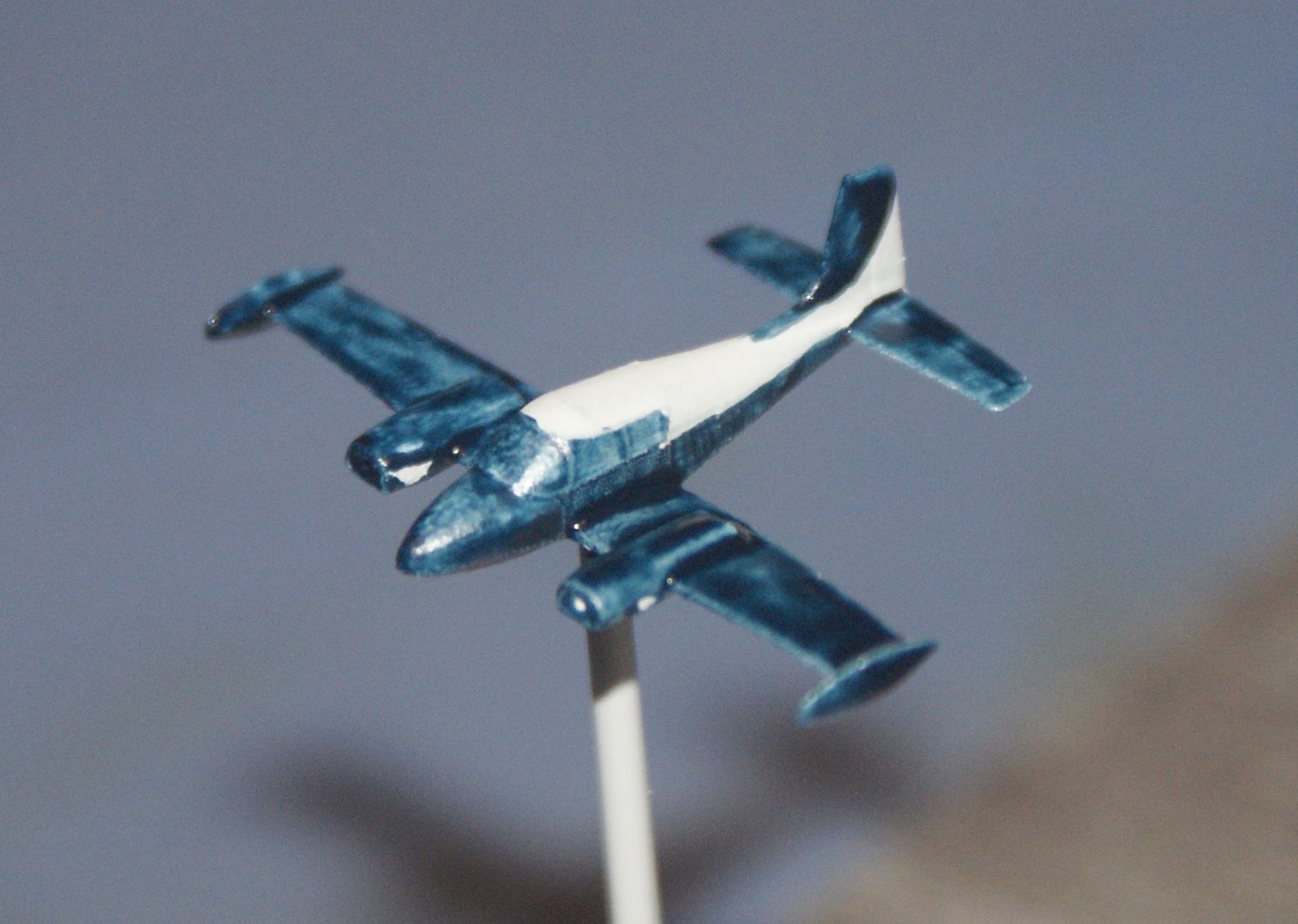
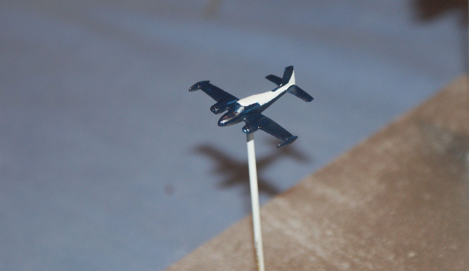
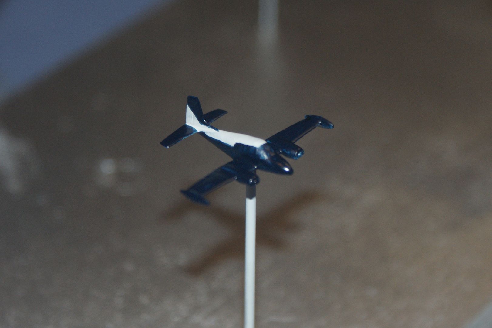
Looking at pictures of U-3A’s I noticed that some had two numbers on the tail and some had only one. For my model, I used only one, “92137”, which represents mom’s birthdate. Upon completing twin-engine training in the U-3A, and then the B-25, dad went on to become an instructor pilot, flying a B-25. I don’t know how his plane was marked, although I understand that it didn’t have any nose art. My model however does have nose art, in the form of a bust of “Bill”, the Naval Academy’s mascot. I only hope that this doesn’t offend anybody, but I guess it is less offensive to some than the nose art of WWII.

The tail numbers on the B-25, “112359”, are my brother’s birthdate. The red tail stripes I saw on a picture of a B-25 painted aluminum, like my dad said his was painted. I liked the way they look, so I decided to include them on my model.
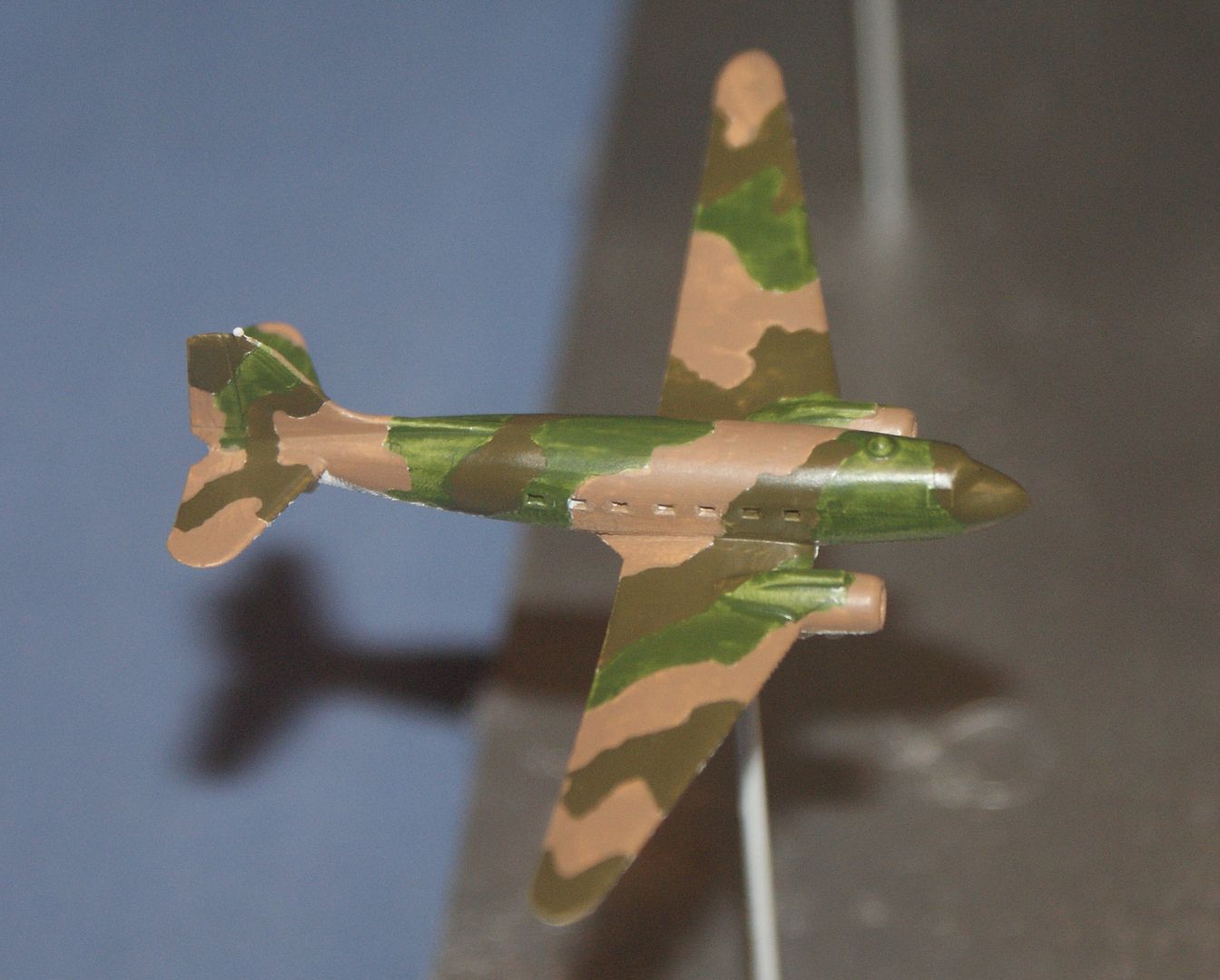
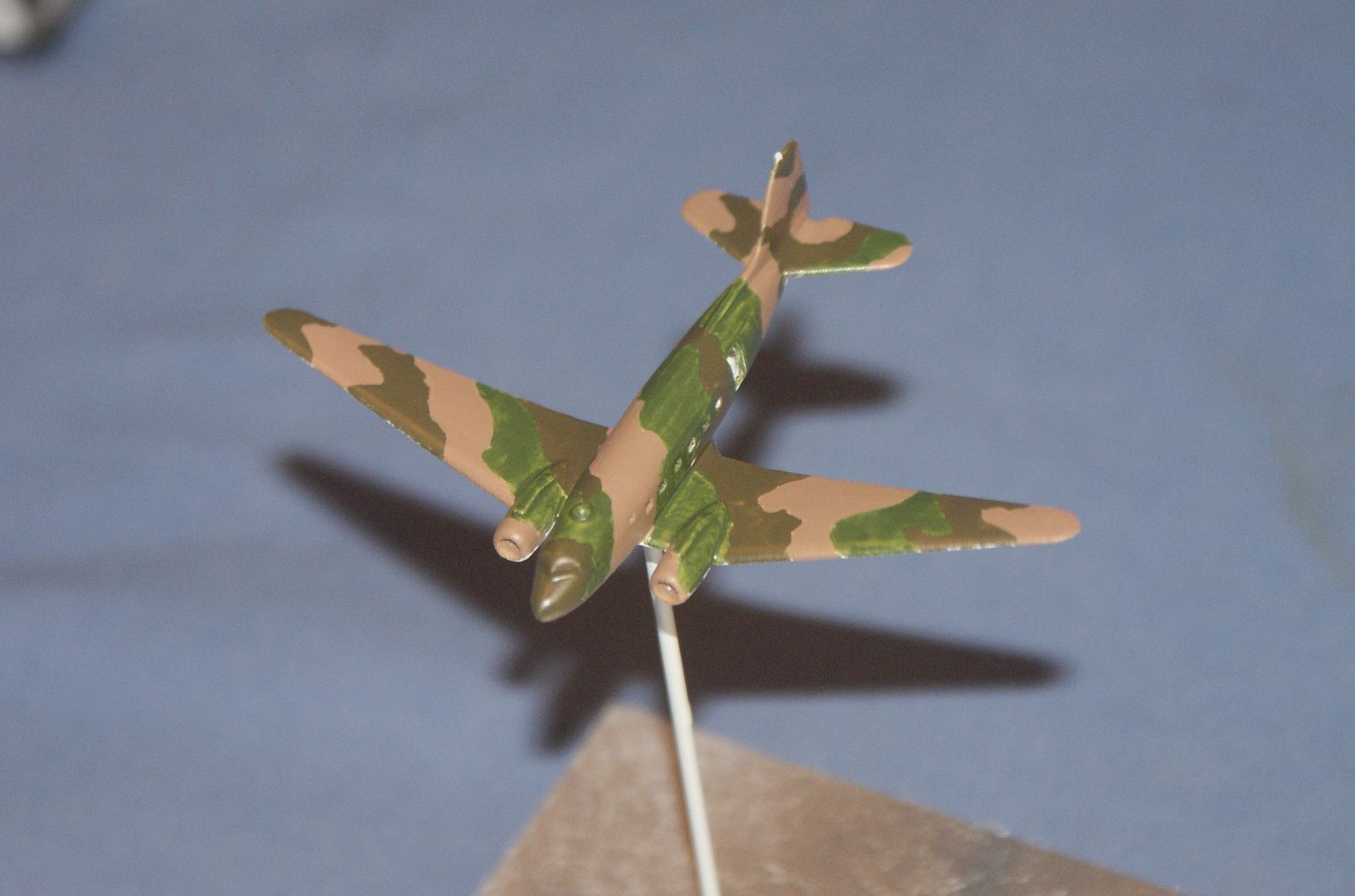
From January, 1966 to October, 1966, dad flew an AC-47, “Puff”, in Vietnam. According to dad’s memoirs from his time in Viet Nam, the natives often referred to the AC-47’s as dragons because of the tracers that looked like a fire breathing dragon. The Air Force Times even called them Dragonships, so the guys called her “Puff” after the kids TV show “Puff the Magic Dragon”. Dad’s detachment commander, Lt. Col. Carter, even had him design and fabricate plaques for the entire 4th Air Commando Squadron, of which he was part of. A dragon is a key feature of the plaque, as seen below, and dad says that they were all hoping that their call sign would be “Puff”, but for some reason SEA came up with “Spooky”. The nose of my model has Puff, rather than the Spooky ghost seen on some AC-47s. The letters on the tail, “RD” are my dad’s and my initials, and the tail numbers, “7561” is my sister’s birth date. I also made red stripes that go on the fuselage near the engines.

Finally, the tail numbers on the T-29, “195881”, are my birthdate. Some picture of T-29’s show them with an American flag on the tail so I included one on my model. I also included the red warning stripes that, like on the AC-47, go on the fuselage near the engines.
Stan, at Cedarleaf Custom Railroad Decals, was great to work with. I e-mailed an inquiry on Sunday afternoon and he responded within a couple of hours. By Monday he sent me a layout, and by Tuesday they were shipped. They arrived Friday, the day after Thanksgiving. So, not only do the decals look good as may be seen below, but the turnaround time from initial contact to receipt of the finished product was excellent.

Before the printed planes arrived, I also had time to order and receive 1” USAF insignia tie pins, which I order from PinMart. The cost for both pins, with shipping was $12.53. The pins are classy looking and I think that they will add some panache to the display.

Yet another task that I accomplished before the printed planes arrived was finish the base. Unfortunately, I screwed up the first one, poorly staining it with a color I didn’t like, so I had to go back to Michael’s and buy another one. Before starting the finishing process, I first made a template that I printed, cut out and taped to the plaque. This allowed me to drill the 5/32” diameter holes for the 1/16” brass support rods in the proper locations. I also drilled holes to accommodate the Air Force insignia pins.

To finish the base, I first sanded the plaque and wiped on a coat of Minwax Pre-Stain Wood Conditioner, followed by two coats of Minwax Red Oak Wood Finish. When the stain had dried I sprayed 7 coats of Minwax Polycrylic at 1 hour intervals, with light sanding between coats. The finished plaque is shown below. I have no idea what caused the “Snail trails”. Still, I like it, even if it isn’t perfect.

Getting the models printed was, as expected, the most expensive aspect of the display. The total cost for printing all of the aircraft and propellers, including a test of the supported version of the prop for the T-28, was $158.06. However, receiving 3D printed parts that you have designed is always a delightful experience and this was certainly no exception. It was a joy to hold the little models in my hand and it softened the pain in my wallet somewhat.
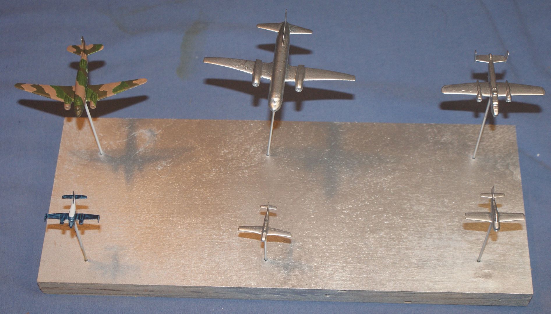
Prior to receiving the models, I had prepared a working base, and cut the brass rods I used to support the planes, so the first thing I did was put the planes on the rods. The 0.063” diameter holes I drilled to accommodate the rods worked nicely. They were snug, but not too snug. The image below shows the unpainted planes temporarily installed on the working base with the brass rods. The spinning props may also be seen at the base of the planes, and the supported props may be seen next to the dime.

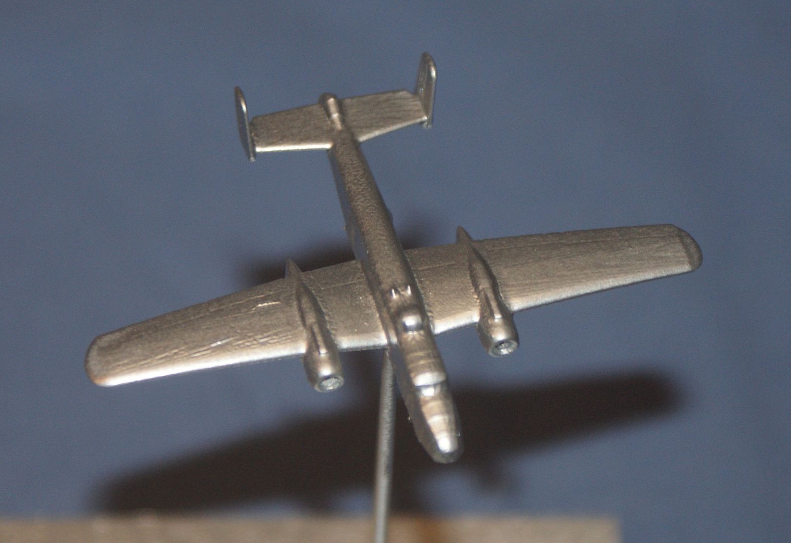
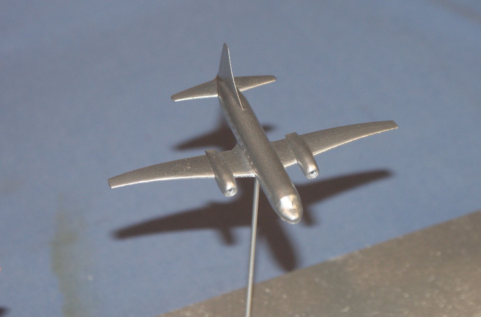
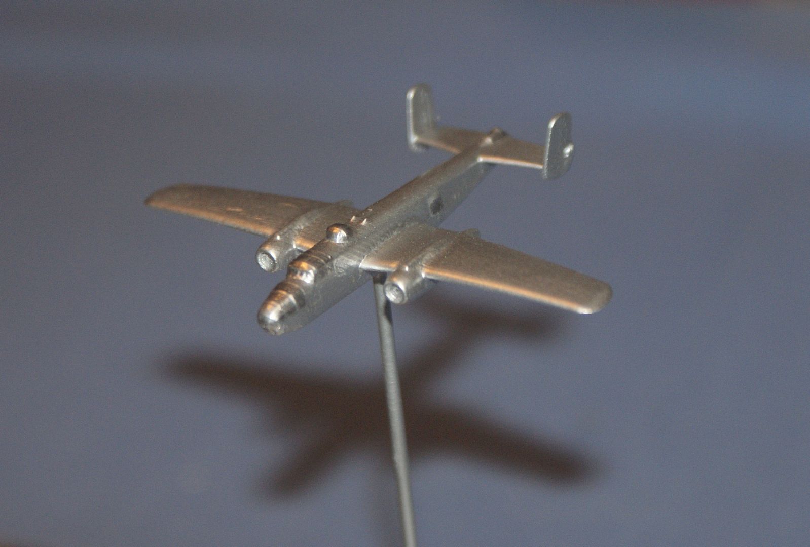
The following images show close up pictures of the 3D printed planes, including the AC-47…

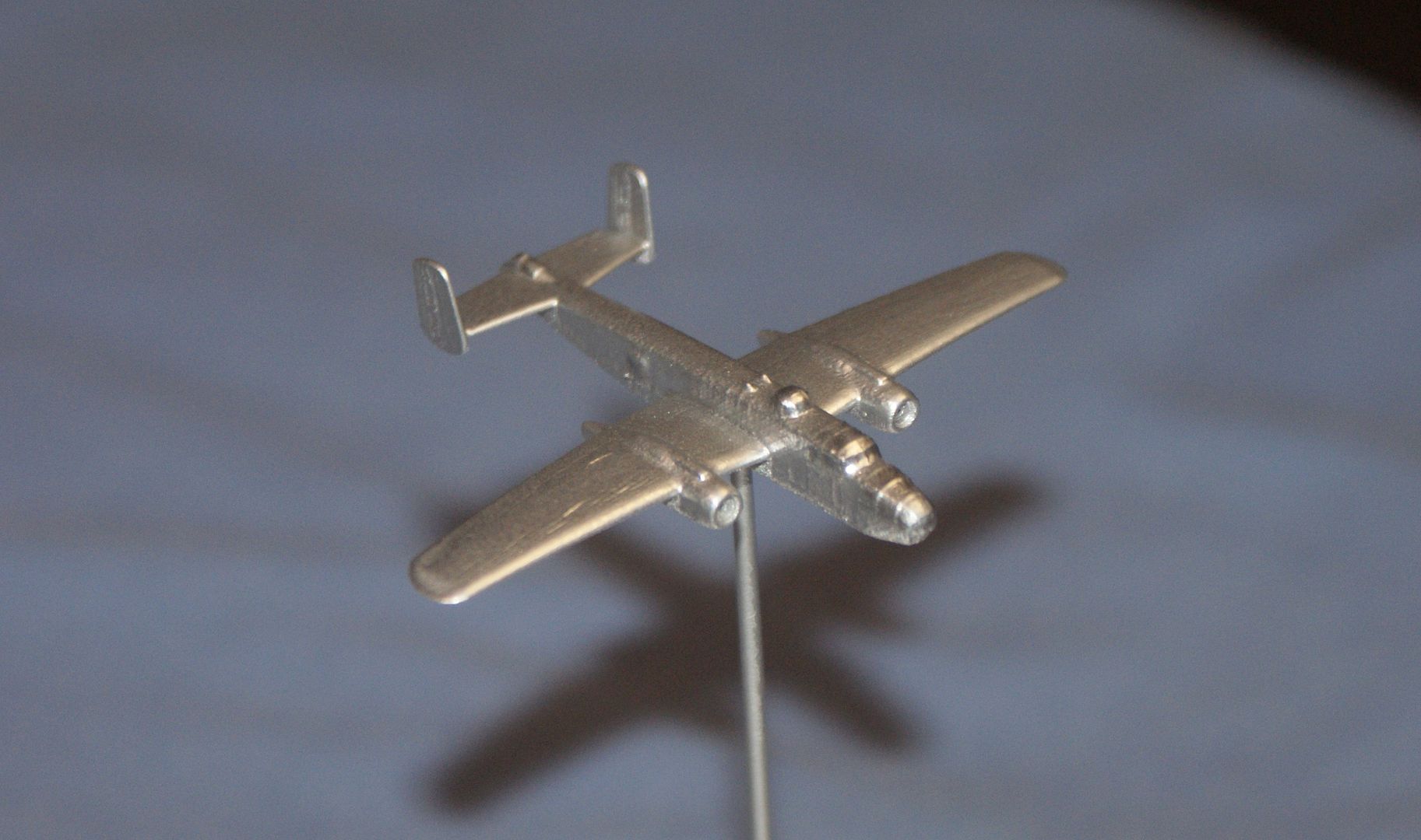
The B-25…

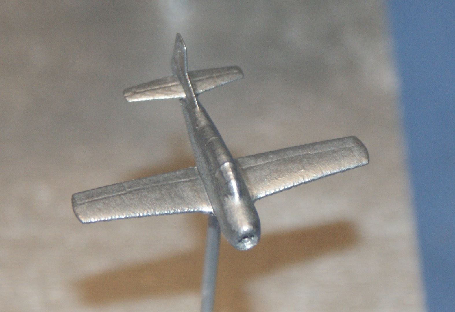
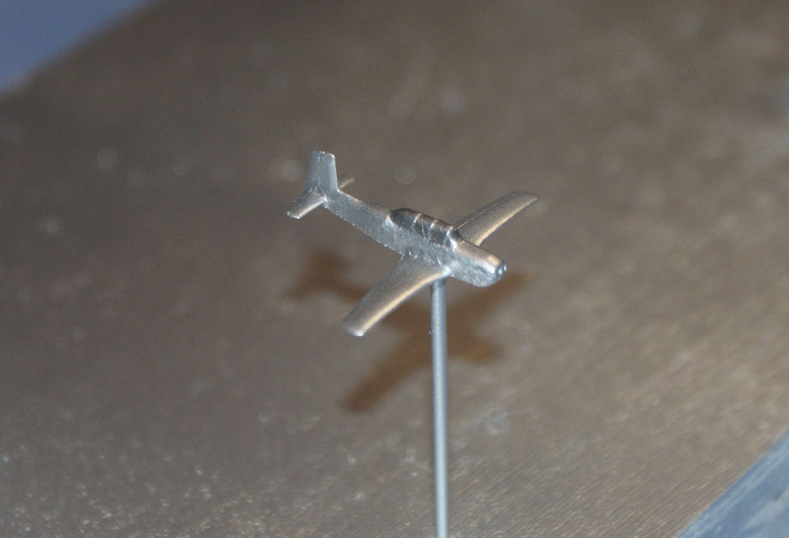
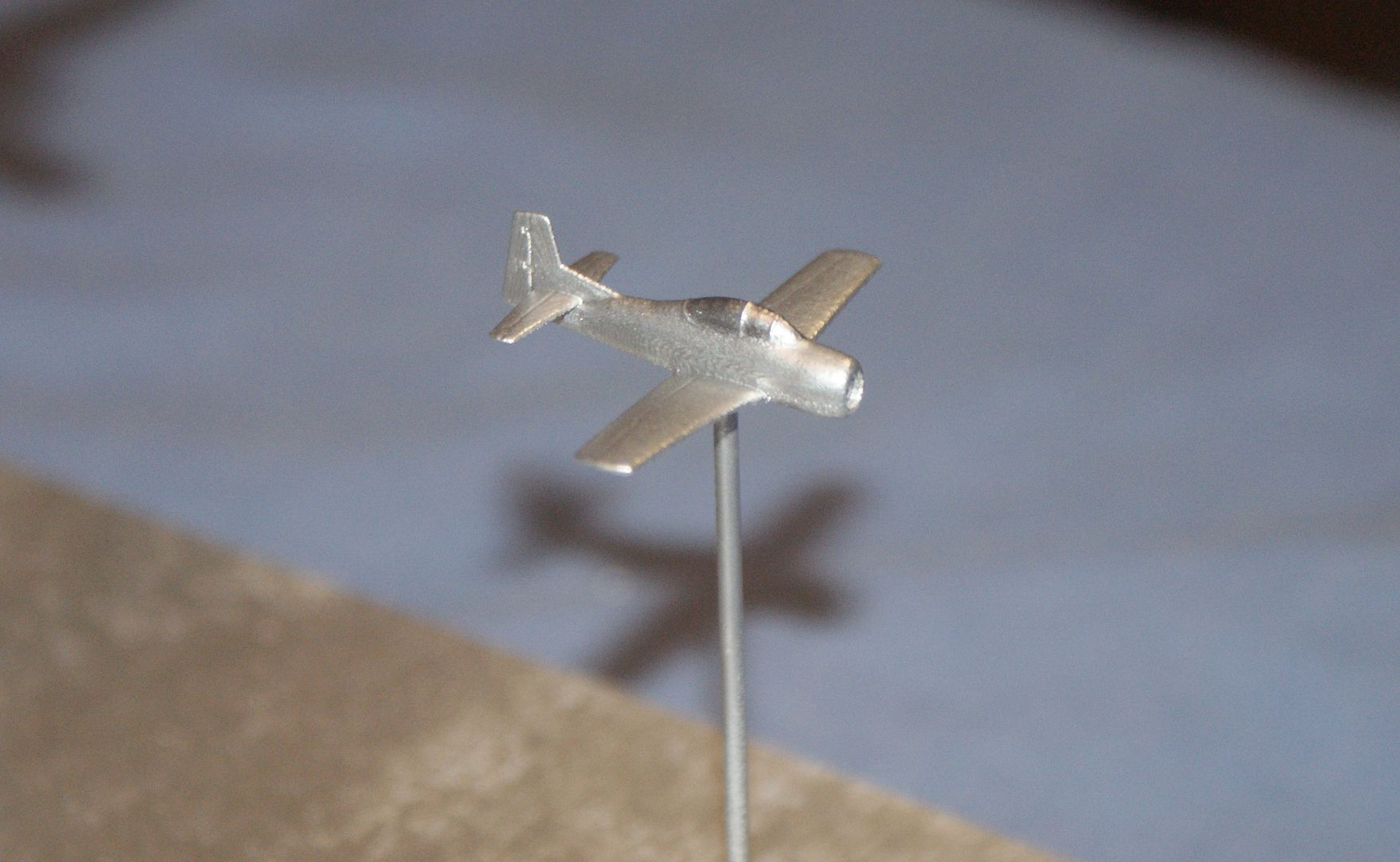
The T-28…

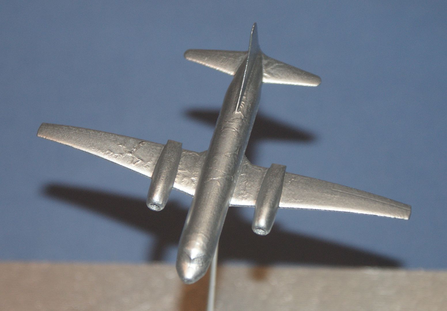
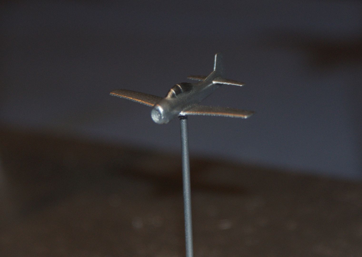
The T-29…

The T-34 (with a cat hair)…

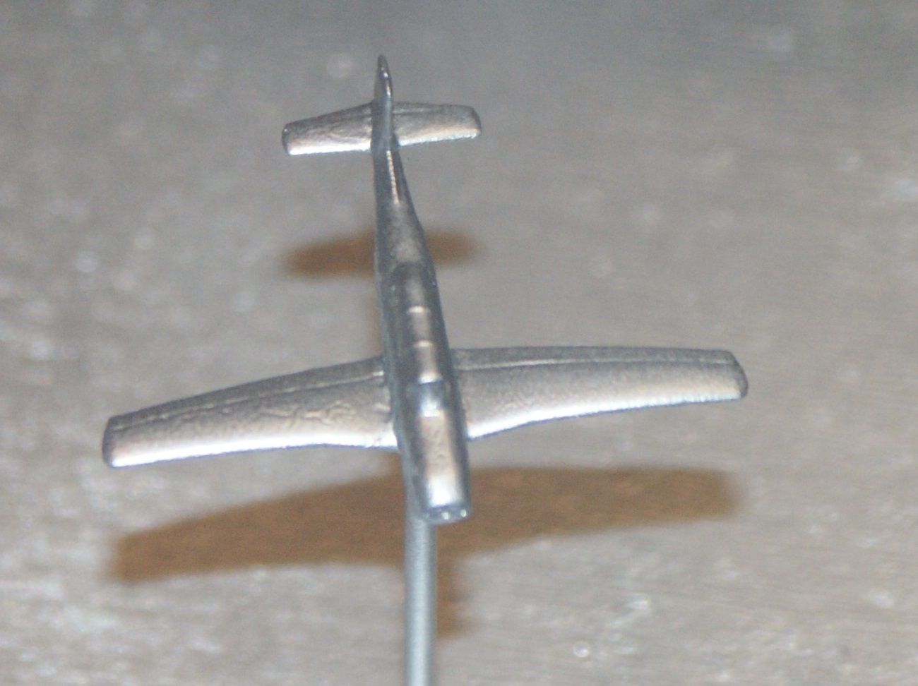
And the U-3A.

Yesterday, I sprayed the planes with a coat of Rust-Oleum Plastic Primer. The only plastic primer I was able to find was a matte white color. I would have preferred gray, but I suppose it doesn’t matter since the planes are going to be painted anyway. Before spraying, I debated on whether to use the brass rods that I was going to use to support the models on the final display or find a substitute during spraying. I decided to just use the rods I will be using, reasoning that I can easily remove the paint from the rods with mineral spirits. If not, I can always cut new ones. The image below shows the planes after the one coat of primer.

So far, so good!
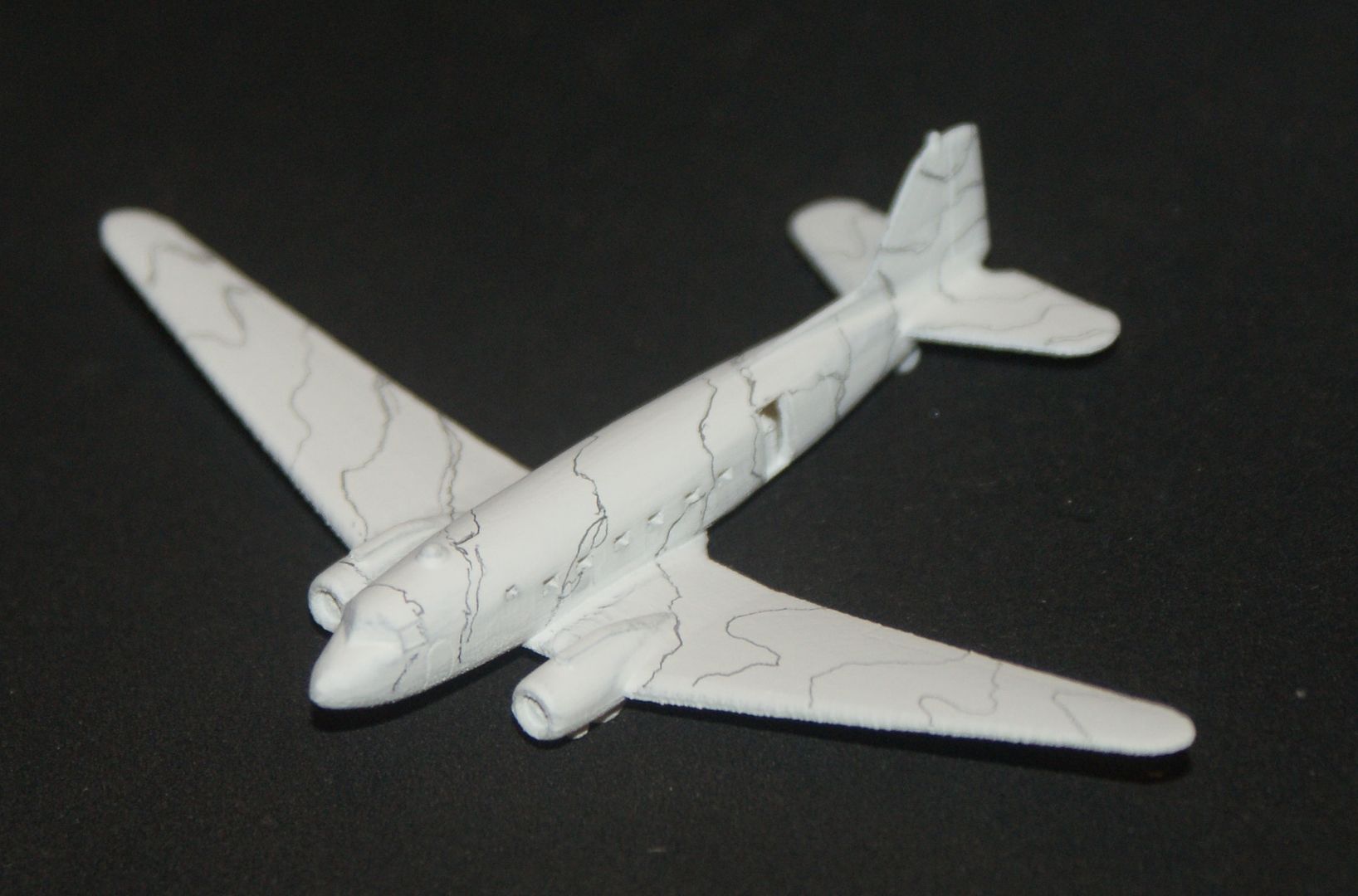
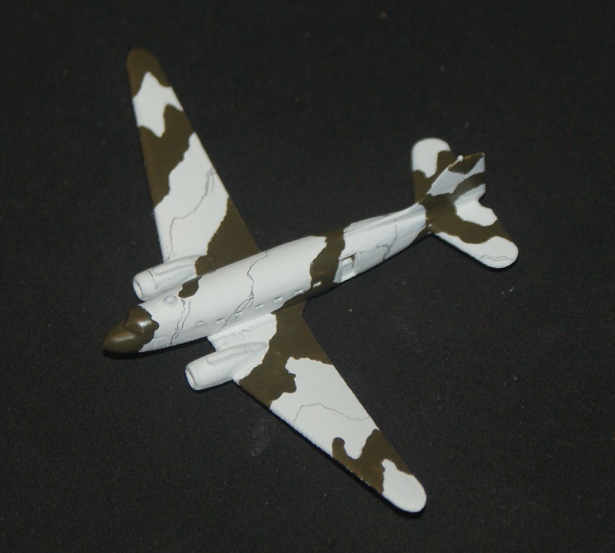
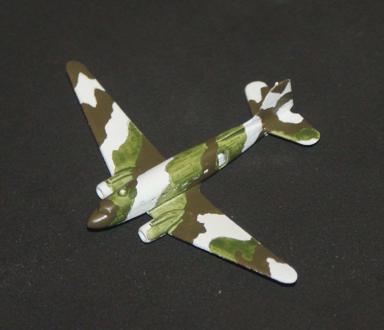
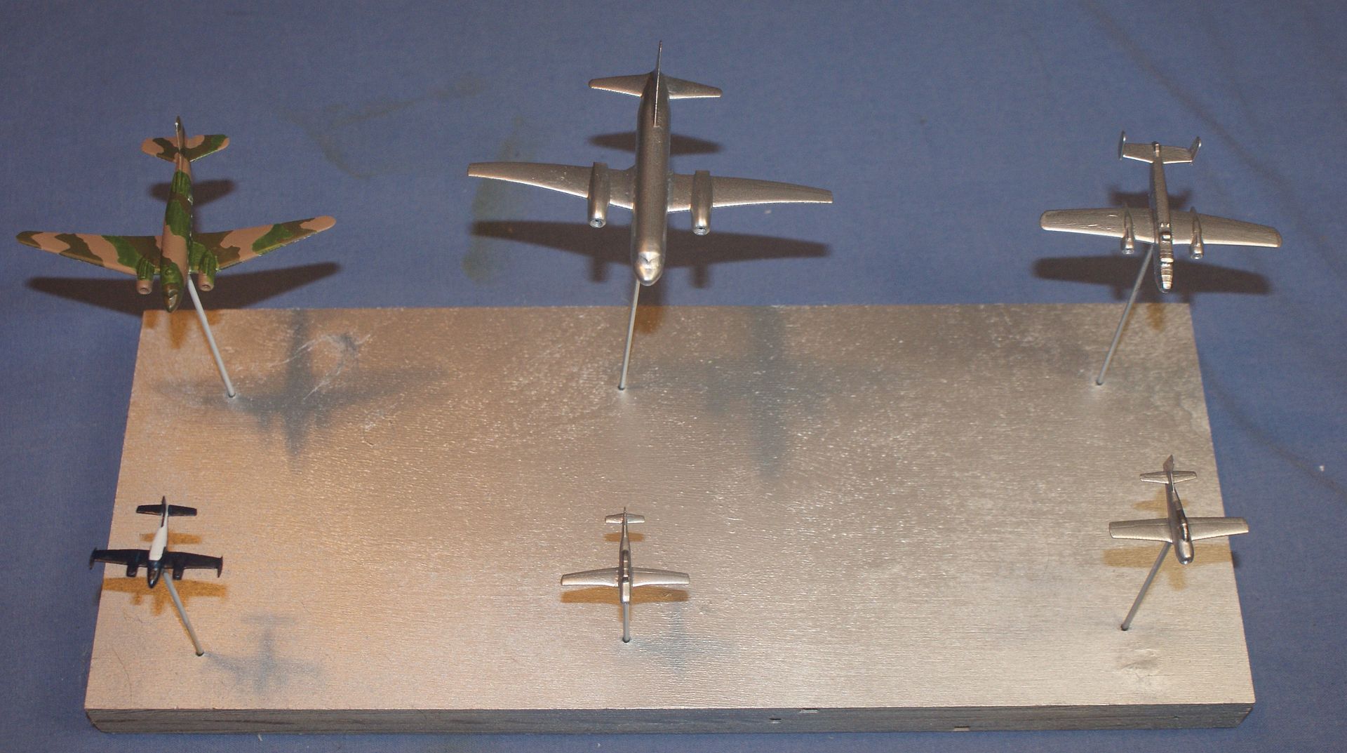
According to dad, the B-25, T-28, T-29 and T-34 planes he flew were colored aluminum, so to paint them I used Rust-Oleum American Accents Satin metallic Aluminum. This did not go so well, especially for the T-29, but somewhat on the others too. The paint “wrinkled” and I have no idea why.


I sprayed them in the garage, which is pretty cold, but the models and paint were warm, and I brought them in as soon as I sprayed them.
Does anybody have any idea why this wrinkling would happen? It seems especially odd to me that the primer appeared to go on nicely, but the paint didn’t. Hmmmmm….