Lol, I’ll bet! Thanks, Buffirn! [:D].
Russ
Lol, I’ll bet! Thanks, Buffirn! [:D].
Russ
Thanks for the good words, Ken! [:D]. And you’re more than welcome, bud. It’s my pleasure.
Russ
Hi, All,
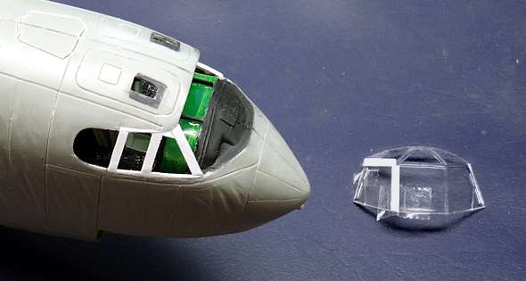
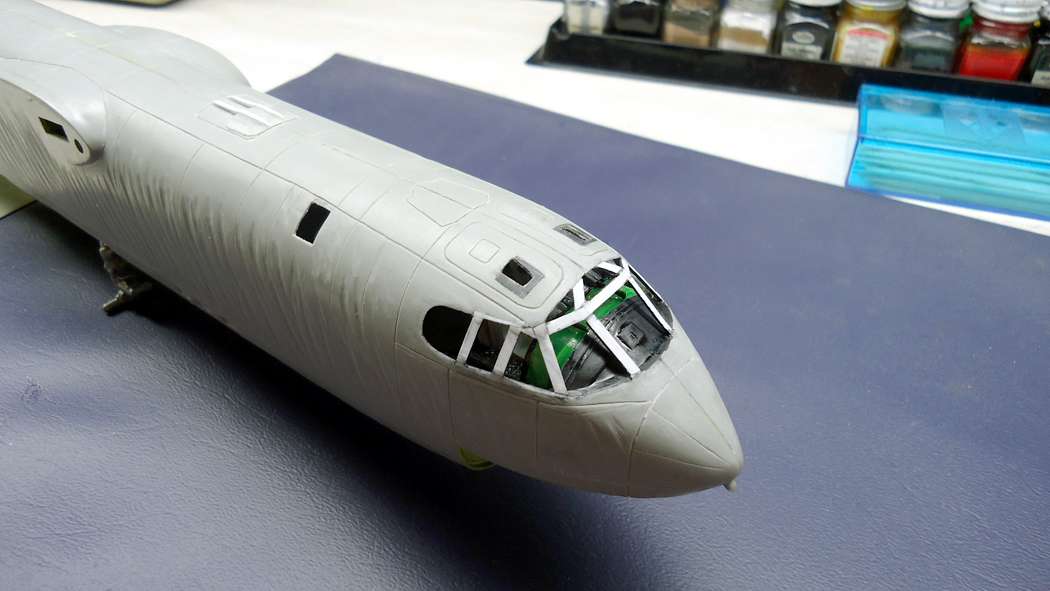
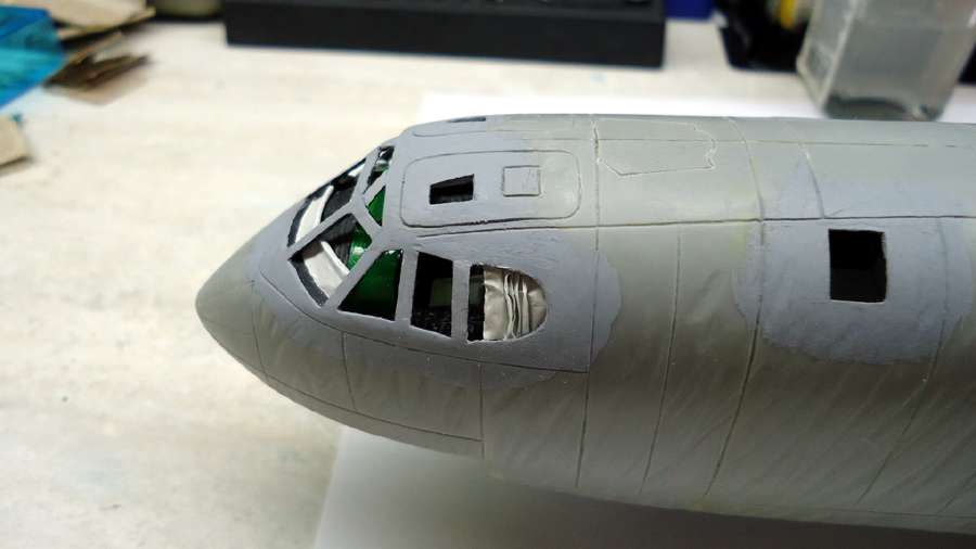
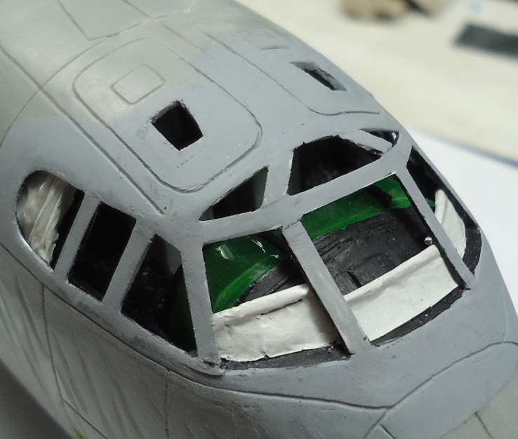
I decided to build up the front canopy as I did the gunner’s canopy, and take Ken & Dom’s suggestions to leave off the clear panels and just leave the canopies open - at this scale, it really doesn’t look bad and you can certainly see the details better. Since there will be a cover over the entire diorama, dust shouldn’t be a problem.
Below are photos of the canopy under construction and finished - it’s not painted yet but I plan to prime the entire fuselage soon. I used the front part of the original canopy as a template and taped the pieces of the frame to it, then glued them at the joints.
Cheers,
Russ


Russ;
Honoured i was mentioned by you, and Ken no-doubt feels the same.
I have a few hints if you want to PM, but that is a great build and
I’ll try to keep up. I like your ‘Open Concept,’ I hope it
doesn’t to much pressure on you to ‘super detail’.
Dom
Facinating build! Was stationed at Da Nang in 68 with the 366th TAC Support Group. We didn’t have the Monkey Killers in there very much:)
Hi, Dogfish7, and welcome!
Lol haven’t heard them called that in a long time! That was pretty much an in-country term [:D]. I was stationed at Nha Trang in 71, not too far south of Da Nang.
Thanks for stopping by!
Russ
Hi, Dom,
Any hints, tips or comments would be much appreciated bud! Please post them here so others can benefit from your suggestions.
As for the “open concept” (thanks for the term!) not much more detail I can add now except blast curtains. At least I don’t have to worry about scratching the canopies! [:D].
Russ
NOTE: Information in brackets [ ] has been copied from a previous thread into this post without responses and comments, so some disconnects in the dialog may be apparent.
Hi, All,
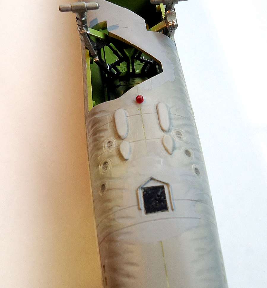
I just added the strike camera window and rain deflector to the undersides, just aft of where the ECM antennas will go. For the window, I used clear styrene covered with a layer of Future floor wax.


**[**I finally got the 47-section hatch cut out. It was a tough job because the plastic is really thick here. This hatch was important to the ECM shop because it gained access to the “ovens” - fiberglass boxes that held our high-power jamming transmitters. Through this hatch, we removed and replaced transmitters and their cooling units, some weighing over 50 lbs each. It also provided access to our chaff dispensers. Each loaded magazine of chaff weighed about 40 lbs (they weighed about 25 lbs empty) and there were 16 of these magazines in a full load, one for each slot in the side of the aircraft. They all had to be handed up through the hatch.
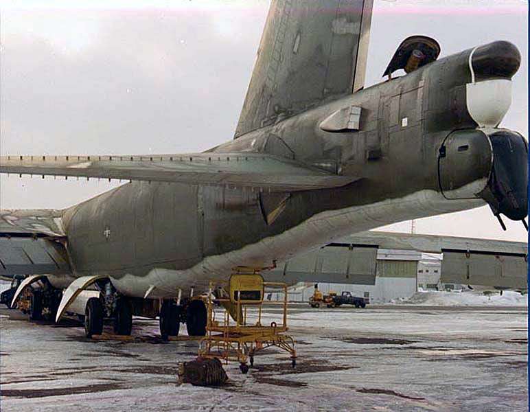
The only clear picture of the 47 Section hatch I could find was on a G (or H?) model, shown below.

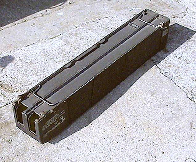
Below is a single chaff magazine. Each was about 4 feet long and was made of cast aluminum and steel. It had two channels for chaff bundles. The magazines were loaded vertically into the dispensers. The dispensers had motor-driven pawls that ejected the chaff bundles. The chaff bundles came in small cardboard packets that were torn open by a small “tooth” when the bundle was ejected.

[
Yup, although much more sophisticated. Instead of plain aluminimum strips, the chaff now is mylar strips coated with alluminum. Much thinner and stronger. It is cut to different lengths depending on the frequency of the signals you want to jam - longer for lower frequences and shorter for higher frequencies. Some of the lower frequency chaff is 8-10 ft long and actually can cause power outages if they get across high power lines. The very high frequency chaff is around an inch long and very narrow - like what you get from a shredder.]
The next step will be to prime the fuselage and wings. After that, I will assemble the aircraft. But before I can do that, I need to build the diorama base so I have someplace to park this monster [:P].
Cheers,
Russ
You will need to park it on a mirror so everyone can see the detail that you put on the bottom! Nice work Russ, again as always! [Y] [Y]
Ken
Thanks for the good words, Ken! [:)]
I know it seems a waste of effort but without this feature added, the view from the side won’t look right. There would be a pretty wide empty space that just isn’t there on the real plane.
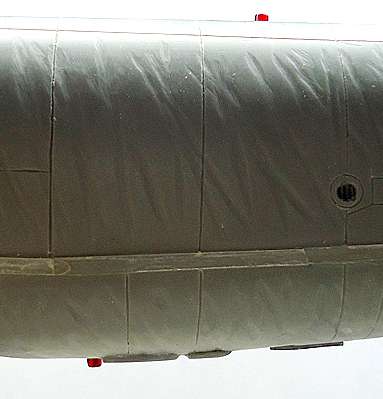
In the picture below, the strike camera rain deflector shows as a line between the last rectangular antenna and the large paddle antenna.
Color me picky [:D]
Russ

Nice job on the research and paying attention to detail Russ. I would never say that it was a waste of effort. It is all a matter of how much pride you have in doing the aircraft you have dear to your heart the justice it deserves! Only modelers such as ourselves can understand that!
Ken
Russ:
You mentioned,“I know it seems a waste of effort but without this feature added, the view from the side won’t look right.” i have to agree with Ken, as he put it so well:
“Nice job on the research and paying attention to detail Russ. I would never say that it was a waste of effort. It is all a matter of how much pride you have in doing the aircraft you have dear to your heart the justice it deserves! Only modelers such as ourselves can understand that!”
As I like to quote:
"God does not subtract from our time on earth
the hours we spend modeling."
Dom
Thanks guys! That means I’m not totally cracked lol [:D]. I’ll drink a toast to both your philosophies! [t$t] [B]
Russ
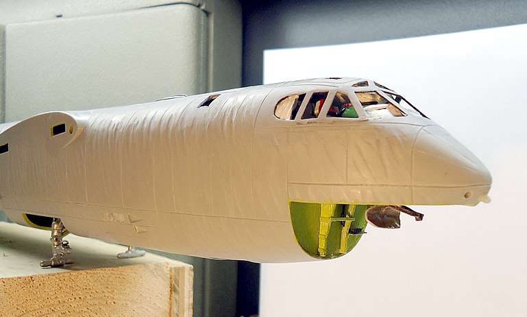
I finally got the blast curtains in and believe me, it was no blast [:D]. It was a real struggle for the side curtains - I should have put them in first before the canopy frames - lessons learned [:)]. The curtains are made of aluminum foil sprayed white on one side. I used a pair of straight tweezers to make the folds in the side curtains. I used small round styrene stock to make the rods for the front curtains. Glue the rods to the un-painted top edge and roll them gently until you get the shape you want.
The front curtains apparently had a spring-loaded roller system that took up the slack down below the window sill. Since there’s no slot at the bottom on the model, I had to place the curtains against the outside of the frames and run my fingernail along the bottom edge to get the curve of the window, then cut along the resulting line before gluing the curtains in behind the frames.
Cheers,
Russ


Those curtains look real nice Russ! Great job! Very realistic looking! [Y] [Y]
Ken
Thanks, Ken! [:D]
Russ
Hello, All,
Below is a picture of the nav radar antenna installed in the chin radome. I was only able to find one photo that showed the antenna reflector from the back so I had to guess at the feedhorn assembly, and the reflector support system. If anyone can provide more information on this antenna setup I would certainly appreciate it.
Cheers,
Russ

A little more progress today - I added the antenna pedestals for the ECM antennas and the transmitter exhaust vents, and also added the top and bottom flashing navigation beacons. I’ll wait until the plane is assembled and painted before adding the antennas.
Cheers,
Russ

![]()
Incredible work Russ! This baby is going to take off and fly when you are done!
Ken
Lol thanks Ken! Not sure I’m ever gonna be finished with it though [:D]
Russ