Small update.
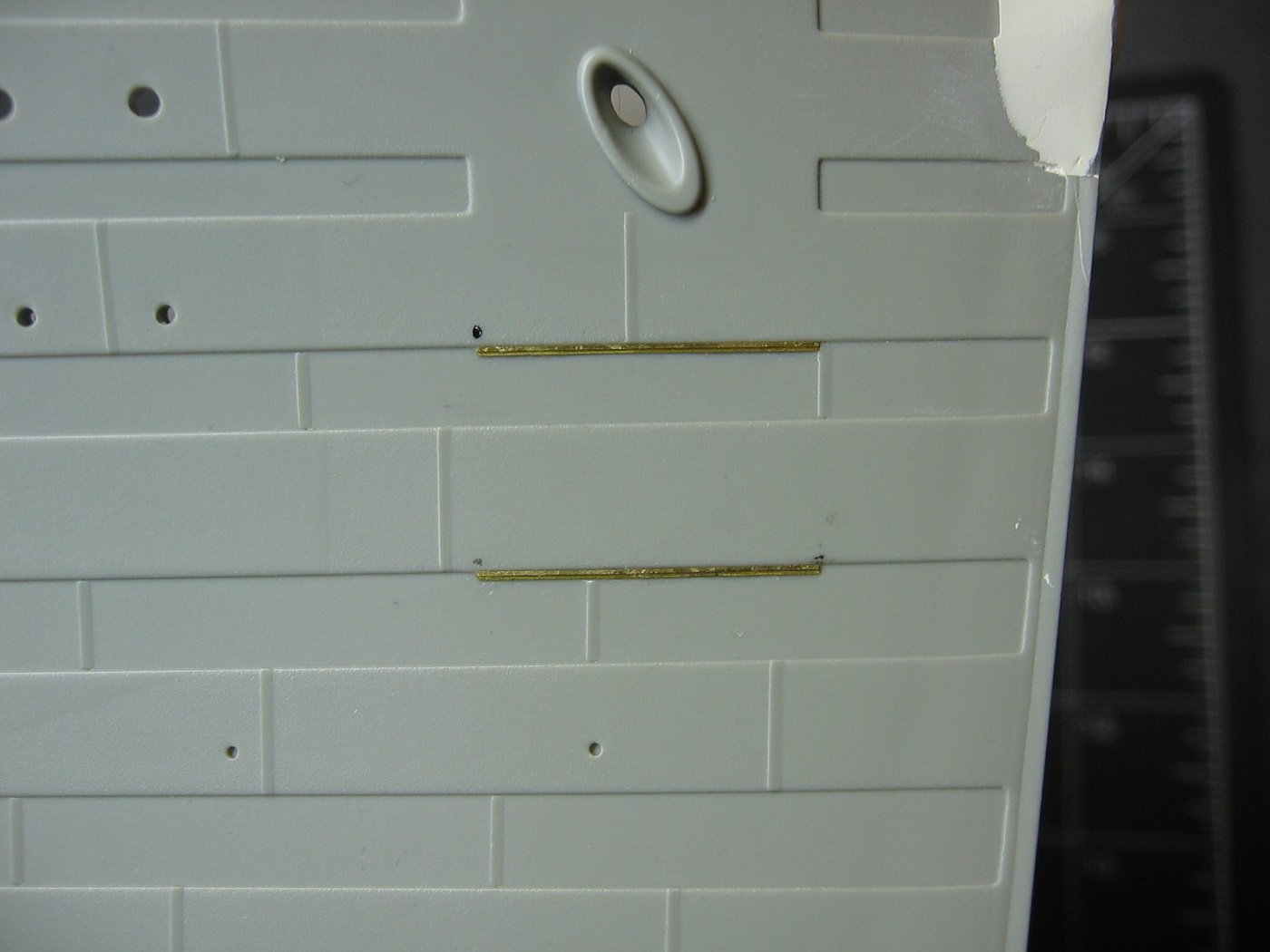
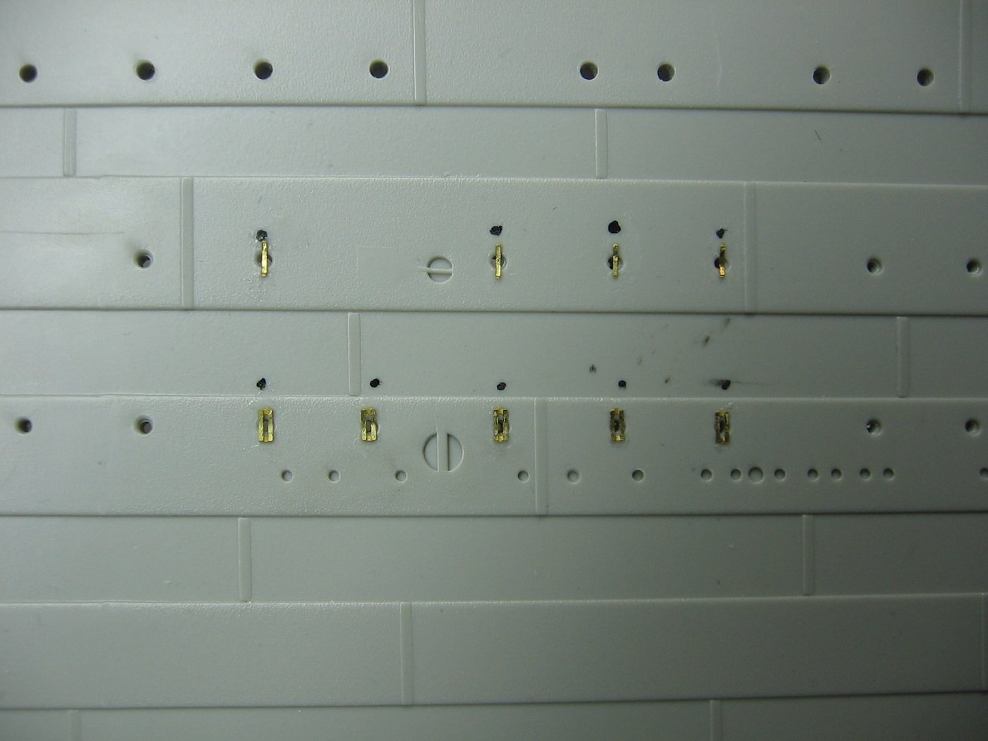
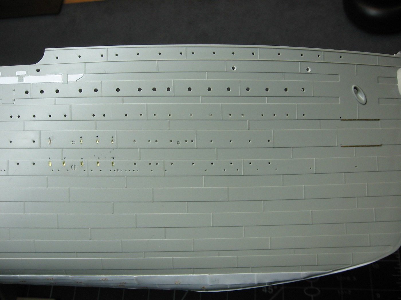
Got the MiniBrass anchor guard bars PE installed on the Port side.
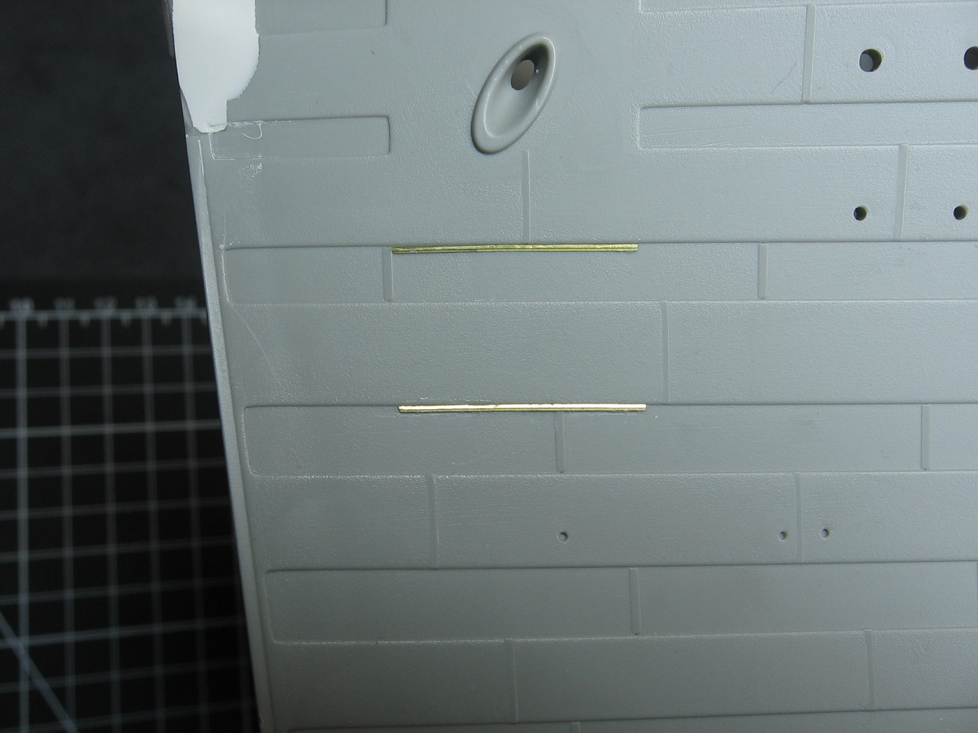
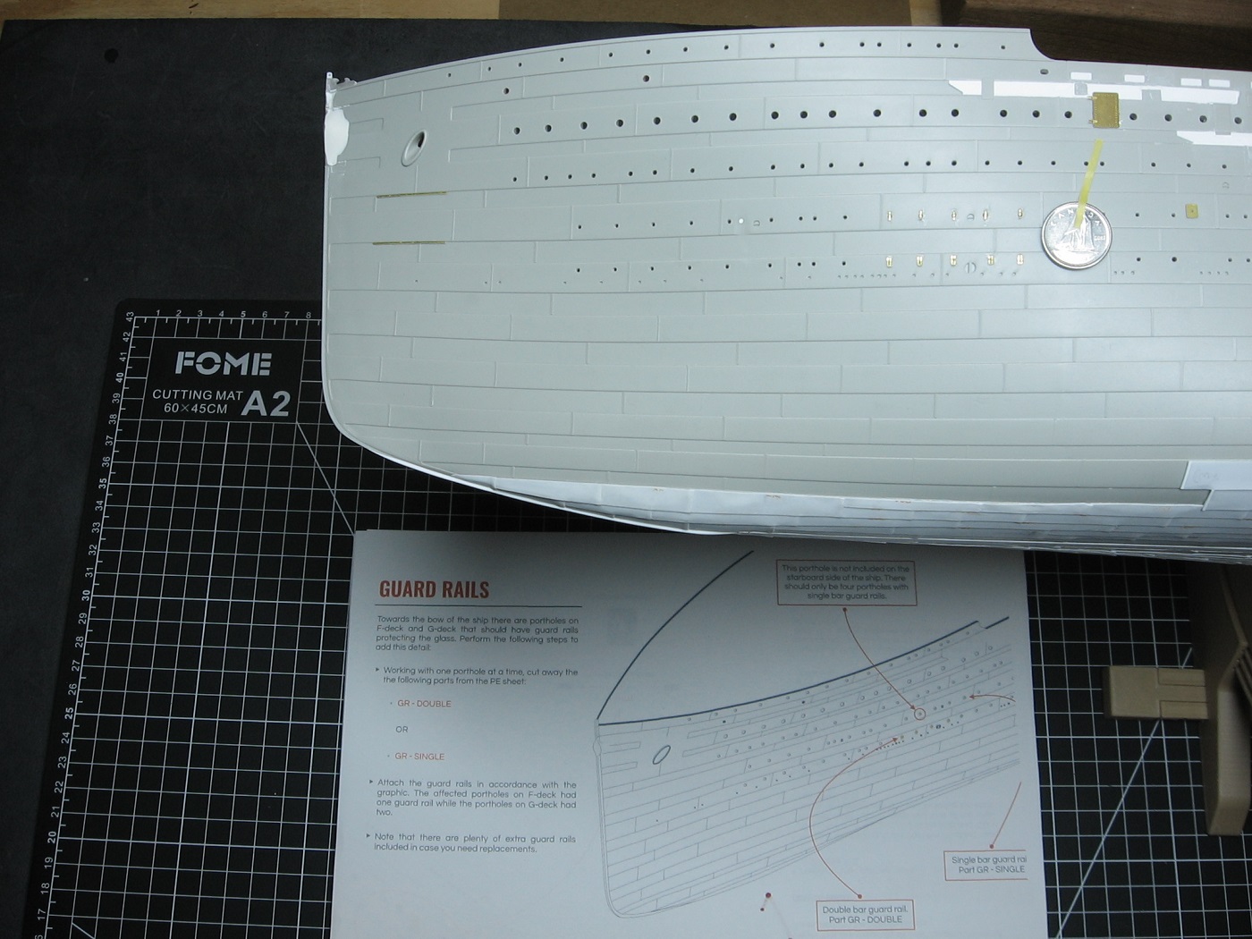
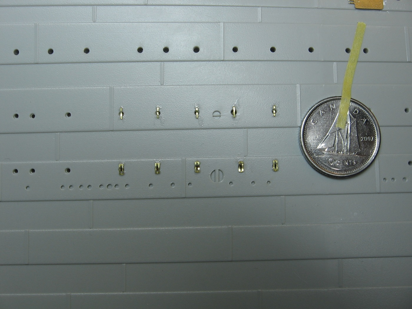
And the single and double porthole guard bars installed, Port side. Dime added in photo for scale reference. This is tiny PE.
Thanks for looking.
Cheers,
Mark
Small update.
Got the MiniBrass anchor guard bars PE installed on the Port side.
And the single and double porthole guard bars installed, Port side. Dime added in photo for scale reference. This is tiny PE.
Thanks for looking.
Cheers,
Mark
Oh my! Not sure the man cave is big enough for that! ![]()
Whoot!! Work on the Titanic has resumed!
Yes. Yes it happily has. ![]()
Ha ha that’s awesome .
Still not enough room. ![]()
Despite golf season still being in full swing, I’ve found some bench time lately.
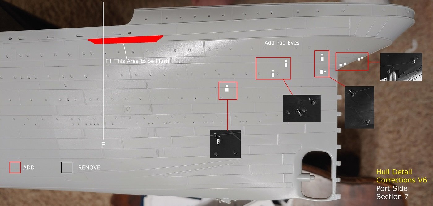
Before continuing with the PE for the hull sides, I’ve decided to do the Pad Eyes at and near the stern next.
.JPG.9b70c558eb55eaf7fc88e36ab2e87707.JPG)
This is tiny PE. Did the larger P1 Pad Eyes first. As evident in the pictures, this PE has two parts. The eye itself, and the base.
.JPG.27176d5ae93570e9f6906950511a6d8c.JPG)
I figured it would be easiest to attach the eyes to the bases with the latter still attached to the fret.
.JPG.db4312e8fb91d7416bc04205cdc3db69.JPG)
.JPG.6289a2843a2ccb3971d9dd2fa86d4257.JPG)
I filed the fret nubs off the eye parts with an 800 grit sanding stick while holding the part with square jawed flat pliers. Tricky.
Then using the Mini Brass instructions, as well as Graham Boyd’s document, I placed the positions of each Pad Eye, by eyeball, on the Port side with an Ultra Fine Sharpie.
.JPG.24ada9812fc5ed540316b7c194f9b08b.JPG)
For the Starboard side placements, I measured the Port side placements from various references points and placed accordingly to make both sides symmetrical.
.JPG.18d8a2353febf08c6bd891449abce20c.JPG)
And a couple of pics showing the P1 Pad Eyes in place. Unfortunately, I somehow managed to get CA glue within the eye hole of most of them. At least, it looks that way. Despite using Vision Aid magnifiers, I found it quite hard to actually tell. I tried cleaning them out while they were still on the fret, but after breaking two of them off, I gave up. I suppose, in hindsight I could have burnt the CA off with a lighter, but that heat would most likely have caused each eye to become removed from each base. Thus, having to start all over. Anyway, not sure how that might have happened. As they are so small, I’m happy with how they turned out. I think the ultimate tell will be when I get paint on them.
As for fret nubs on the base parts, I cut as close as possible to the base edge. Consequently, I manage to avoid any nubs on the bases. If there are any there, I couldn’t see them.
And finally, as far as I could tell from instructions and reference photos, the two aftermost Pad Eyes were on the centerline (which makes sense to me). As a consequence of that, there is one extra P1 and one extra P4 provided.
.JPG.51acd2223462cc858e3cfc2a4167f437.JPG)
.JPG.5bb478080ef4e09047e30d9a19bc10b9.JPG)
Hoping the smaller ones will go as well as these ones did.
Thanks for looking and cheers,
Mark
Yes, it’s live again! ![]()
That PE is so tiny. I’m always impressed by all the planning and pre-work you do before placing a single piece. Looking good!
mistermeester, I tip my hat to you for installing all of this PE! It’s going to look fantastic when it’s completed but you may need an “intervention” when you’re done.
Tremendous and precise work so far. Following with interest.
@MR_TOM_SCHRY Intervention indeed! ![]()
Cheers,
Mark
MiniBrass Pad Eyes P2, P3, P5, and finally P4 attached. Pad Eyes complete.
.JPG.fcecdfebd4b8e0fac7796ea2b5f11190.JPG)
.JPG.8a530396a84bbb70f4a40ceadbc62973.JPG)
Not perfect by any means. A few are slightly crooked and there is excess CA glue here and there.
Probably goes without saying that the P4 Pad Eyes (the smallest) were the hardest.
The white object in the tray on the left in the first pic is a cat whisker. I used that for applying a tiny drop of CA glue to each P4 base before attaching the P4 eye to the base. I forget where I heard about using that as a tool for small amounts of CA as it was quite awhile ago. Perhaps a member of Model Shipwrights of Niagra, but I’m not sure. This is the first time I’ve employed a cat whisker for that purpose and it worked out quite well. I used a glue looper for all the other gluing.
Having said that, one lesson learned with this aspect of my build is I think I underestimate the power of CA glue, and tend to use too much. Looking forward to working with it more. I need to find something to practice on with it.
As for fret nubs, I did not bother sanding/filing any nubs off the remaining PE beyond P1. I figured it’s so tiny and hardly noticeable that it wasn’t worth the bother and risk of losing some of the parts. I considered cleaning them up (fret nubs and excess glue) once attached to the hull, but upon closer inspection with my Vision Aid magnifiers, I’m going to leave well enough alone.
Another lesson learned is my eyes aren’t what they used to be. Despite using the magnifiers, this PE (especially the P4 eyes) was somewhat difficult to see and work with, but I managed. Hoping I will never have to work with such small PE ever again.
I suppose now, the hardest trick of all will be making sure they stay intact. (Read: not get careless and bump them off).
One final thought on the Pad Eyes regarding mention of mine upthread of the hole of the eyes getting CA glue in them. How did that happen? Well, in working with the subsequent eyes, it became apparent. It is quite difficult to attach an eye to a base while maintaining a vertical aspect of the eye. Often they wanted to just flop on their side once they came into contact with the drop of glue. Hence, once on their side and in the glue, that glue gets into the hole. Just a heads up for anyone else who might be using this aftermarket kit on their model.
Thanks for looking and cheers,
Mark
Interesting tip on the cat whisker. I’m forever looking for smaller and smaller applicators for ca. been using some cheap sewing needles lately. Going to hit up the neighborhood cat ladies!
I have ~ a dozen saved in a tall pill bottle. Having used one now, it appears that’s a lifetime supply as I discovered once the tip gets too globbed up, just trim it off with scissors! ![]()
Cheers,
Mark
Small update.
Got the starboard side anchor guard bars and porthole guard bars glued on a couple weeks ago.
In so doing, I discovered a mistake in the instructions. The location of the non-existent porthole indicated (starboard side only) is not where the instructions say, but rather ~20mm further aft. But it’s a moot point anyway, as Trumpeter did not even mold this porthole into the hull, and therefore, it’s obvious.
Golf season is officially over for me (as of 10 days ago). I’ve been busy with chores around the house, transitioning from summer to winter. Getting back to the bench just now.
Next step will be starting work on the MiniBrass Hull Profiles PE set. This set is quite extensive and will transform the hull significantly.
The set arrived (last May) damaged. All three sheets bent. I assume this occurred during shipping. I emailed the proprietor advising him of this. I mentioned I thought I could make the damaged product work, but suggested he might want to re-address choice of packaging for future orders. He replied that this is the first time he had a report of damage and assured me that he’d replace any parts that won’t work. Fingers crossed.
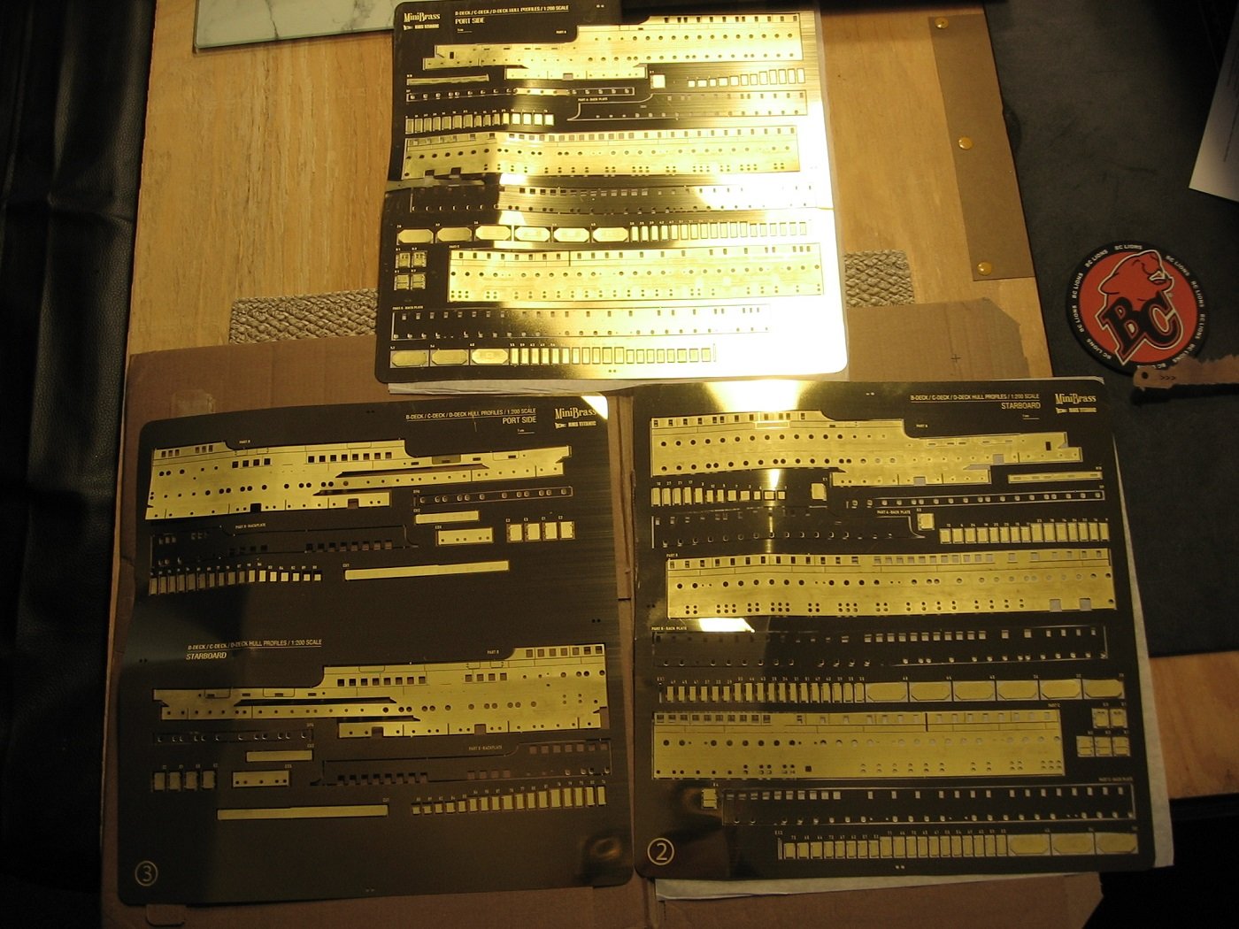
Intro to the instructions…
.JPG.44c74fd336b668e2c61d9a40eaf499e1.JPG)
General information page…
.JPG.2df317bbe94a45fdb1633afa152aefc3.JPG)
First three pages, describing the first steps…
.JPG.c261fc54b17419fe70655e46eb84491c.JPG)
.JPG.2b020a91519f8c49808889c1759ba66d.JPG)
.JPG.019a52cc0a5010cf02bf31fce1ed8824.JPG)
Expecting to get started this afternoon. Should be fun.
Thanks for looking and cheers,
Mark
Argh. Didn’t take long to have a couple of issues. I take full accountability for my mistakes, but some clearer and more comprehensive instructions would be nice. But that’s part of scale model building, isn’t it?
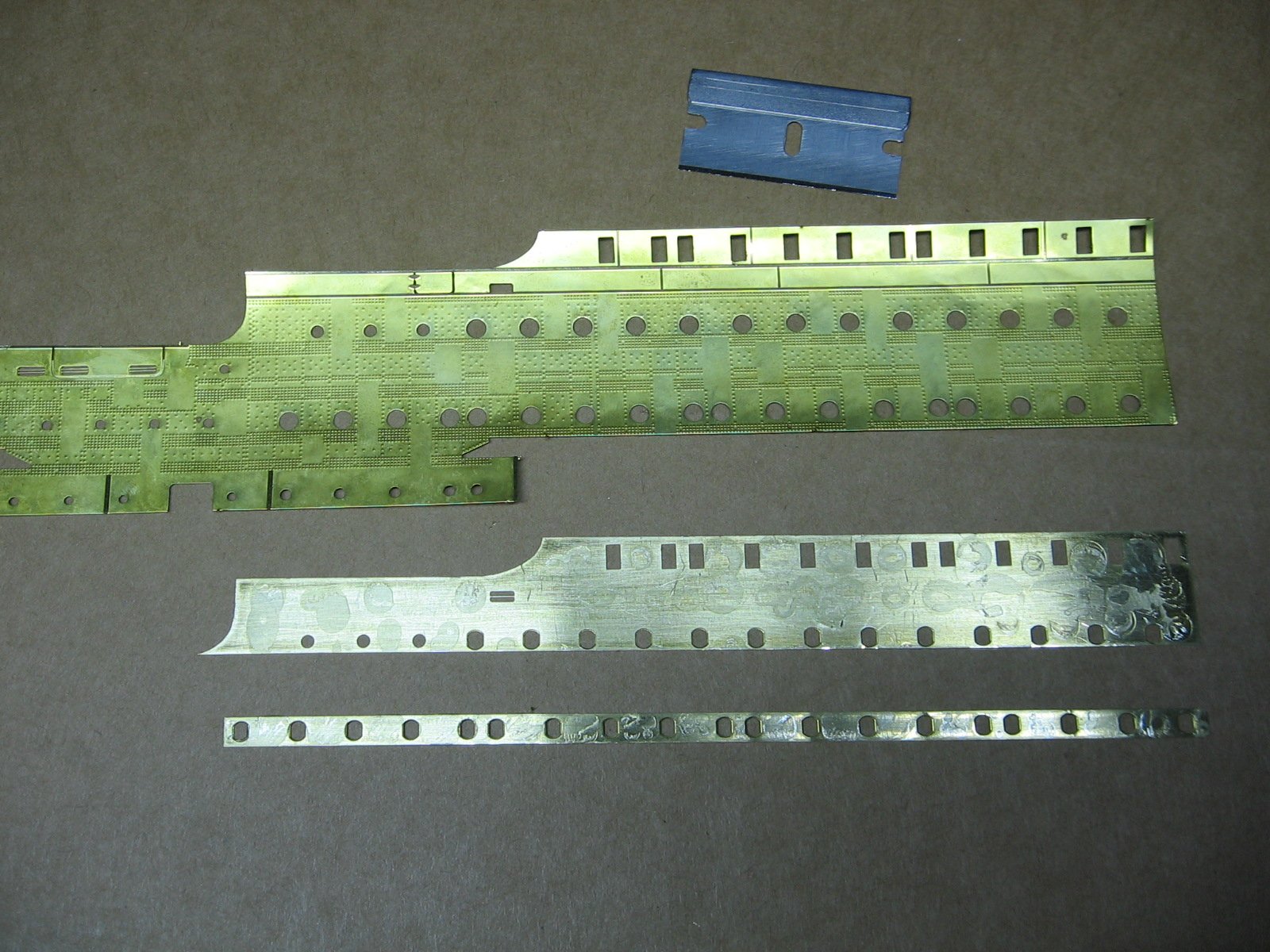
The first issue. Fitting Back Plate A, for the Port Side of the kit.
.JPG.d790bc180fc0ffecbaf0a6313e74f4a1.JPG)
.JPG.9c3605299856b5882a7899a3497fe774.JPG)
As one can see of the port holes within the blue oval, I did not get the back plate lined up properly. The way the instructions are written suggests that the back plate can, and ought to, be fitted in place with Plate A upside down. No. This is not the best way. Don’t do what I did.
Upon gluing Back Plate C to Plate C (haven’t done B yet), I found that what’s better is to flip it back over to topside up and work the underneath back plate from above, with a scriber tool. The “Utley” aspect of said portholes, as well as the inside portion of the window frames, are visible and the back plate can be manipulated into position this way.
.JPG.db1c2b0c03ccb149b29e36f2499fd68d.JPG)
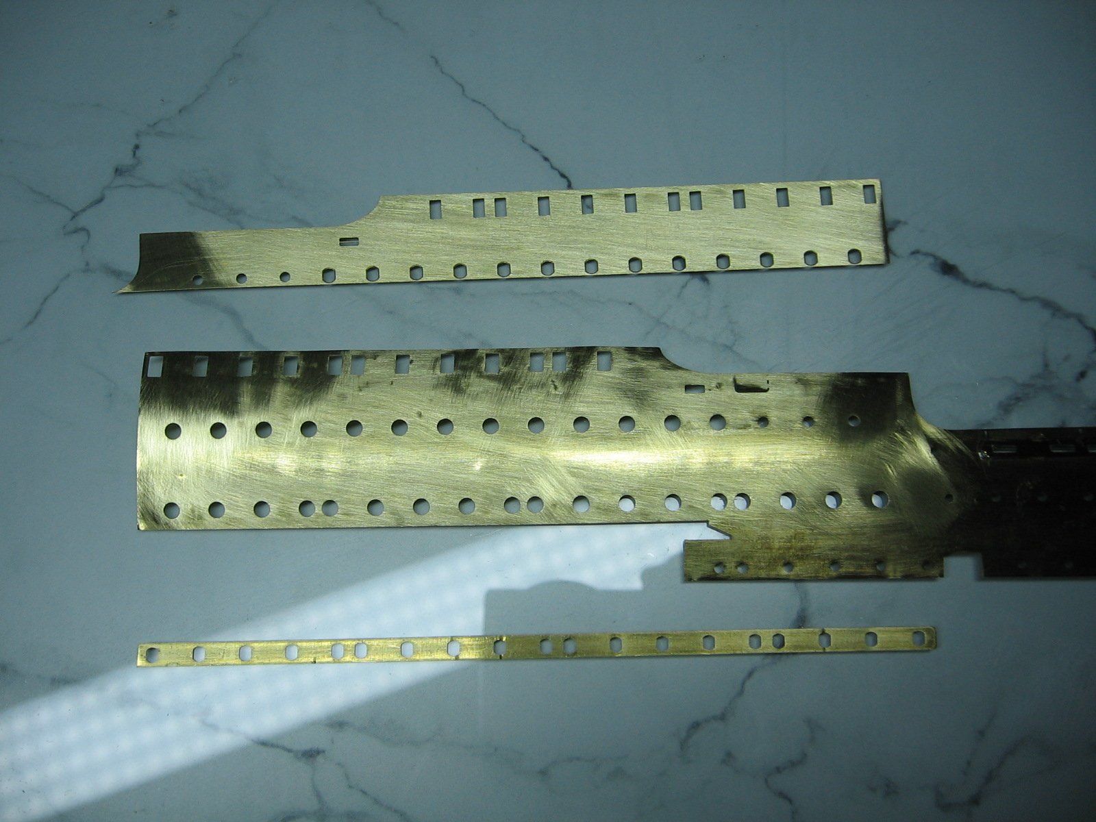
The second issue. Completely got the placement of Back Plate DP wrong.
.JPG.30e02c99d5e092fee246bf56ab3581fb.JPG)
.JPG.aa93eaec6201c502944d013dd5fe5ed3.JPG)
The end in the blue circle needs to be at the end of the green circle. I was wondering why there was no port hole in Plate A for this end of the back plate. Further, I trimmed the end as it was slightly covering the adjacent smaller port hole by ~1mm. I had just assumed this was a manufacturing flaw. Nope. Modeler flaw.
Having said that, the instructions could be better.
.JPG.ccd3be52cd62e61f4a0a580ba933b4cf.JPG)
I’m a visual guy and a better diagram would have gone a long way. The contrasting color of blue (the back plates) to grey (the fret, etc.) is not very evident in this particular spot. Further, all the port holes of this back plate are indicated in white…except for the one port hole at the left end, where the red arrow points. Yes, turns out it is indicated, but in extremely hard to see, and easy to miss, grey. Just a poor visual representation. Had it been indicated in white, like all the others, it would have been obvious.
Great. What to do? Am I going to have to order another sheet and go through another three months of waiting for it to ship? Thankfully, no.
I managed to separate the back plates from Plate A with a straight razor. (Gorilla two part epoxy glue used.)
And cleaned up with a sanding stick. Ready for attempt #2.
I’m happy, and relieved, to announce that attempt #2 was a success. Back Plates A and DP are now glued on Plate A correctly.
Thanks for looking.
Cheers,
Mark
Excellent save! As good as aftermarket parts are, I agree the accompanying instructions a very lacking in most cases. I usually walk away for a day or two to let things like this perculate in my head for awhile and the solution presents itself.
@mrb865 Thanks. Yes, it’s not my first issue with aftermarket kit instructions. Buyer beware is what comes to mind. And good advice, re: patience.
Cheers,
Mark