That’s an impressive Titanic reference library there. You weren’t kidding about doing your research.
Good luck with it! I’ll be cheering you on from the sidelines.
1 Like
Same for me. When I got back into modeling back in 2000, I had the full set of FSM magazine in binders from 2000 to 2005, we ran into some financial stuff so I stopped my subscription. Had the magazines until a couple years ago when they were all damaged by a fire in my house.
1 Like
@PhoenixG Great little build, and thanks for the Titanic build encouragement!
@fxsti03-42 Sorry to hear of the loss due to fire. Thankfully you’re ok though. I’m contemplating purchasing digital and hard copy back issues of FSM. Just waiting on a certain voucher due to January participation points ![]() . Tick tock
. Tick tock ![]() .
.
Cheers,
Mark
1 Like
Progress has slowed somewhat. Wife had hip surgery three days ago and most of my time has been devoted to that lately.
Continuing with the Mini Brass Hull Details PE sheet…
I applied the zinc anodes and reinforcement plates in the vicinity of the stern frame. Zinc anodes are the smaller squares, the reinforcement plates are the larger.
Not too happy with how the zinc anodes turned out. I did the Port side first…

I have a $15 CDN manufactured pick up tool, but it proved to be useless, so I crafted a homemade pick up tool made from a round toothpick and blue tack (as seen in the next image; thanks to FSM for the tip). I suppose the ball of blue tack is too large for these applications as, upon placing the zinc anode, I could not actually see the photo etch piece. I figured I’d just get it on there (CA glue already applied) and then shift it into position accordingly. However, the CA glue set up immediately and it is what it is. The zinc anode should be butted right up to the plating below it.

The placement of the pieces here are what I intended to achieve, however, the zinc anode and the adjacent plating below clearly do not align exactly, indicating that I did not quite get the angle of the upper end on that stern frame plating correct.
Bottom line is, the placement of the zinc anodes, one side to the other, don’t match and the Port side zinc anode placement is inaccurate (too high; should be right up against the plating).
I considered trimming the styrene on the Starboard side, to match the Port side, but that plating matches now as it is, so that would just change one problem into another. I also considered trying to pop off the Port zinc and reposition it, but I had visions of the piece flying off into the carpet monster’s gaping mouth if I tried that.
In the end, it is what it is. This model will not be displayed in the middle of a room with both sides in view. One side will be up against a wall. Not sure which side that will be yet. Depends on which side has more mistakes. Chalking this up as a learning experience. One of my next tasks will be to make another pick up tool with a much smaller ball of blue tack.
Further, technically the reinforcement plates should be flush with the plating around it. Having said that, I’m okay with how I placed those.
I proceeded to then move on to the so called “Safety Bars”. Some of the Sidelights (aka Portholes) on the Titanic had bars over them to protect them from the Anchor Cables. Nine on the Starboard side, (five double and four single), and ten on the Port side (five each). I got as far as cutting them from the fret. Here’s a picture with a dime for scale reference to indicate just how tiny this PE is.

Four single bars are in the left container, five double bars in the right.
As I cut these from the fret, they bent from the knife pressure. That’s how delicate they are.
Another hurdle I have with these, besides just trying to get them glued on, is that most, if not all, still have an attachment nub remaining on them from the fret. I’m interested in advice on how I can file and/or sand these nubs off, seeing as they are so tiny. I’m thinking glue them in place first and then try dealing with the nubs once they are secured in place. Any suggestions on this would be greatly appreciated.
In the meantime, I’ve decided to move on from these, for now. Instead, moving on to the second MiniBrass PE sheet I purchased, Coaling Doors and Cleats. Beginning this sheet with the Coaling Doors.

The only reason I purchased this sheet is because there are two molded Coaling Doors missing from the Trumpeter hull. But seeing as I now have the sheet, I figure I might as well do all 44. There are 22 Coaling Doors on each side.
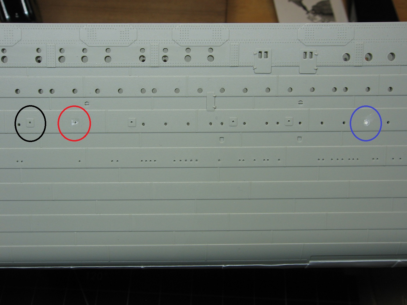
The black circle represents a Coaling Door as molded by Trumpeter.
The red circle represents a molded door already chiseled off by me. Happy to see the indentation remains. Will aid in positioning.
The blue circle represents one of the two missing coaling doors. A porthole was here in its place, which I had previously drilled out. Hence, the putty fill.
Thanks for looking. Suggestions are welcome.
Cheers,
Mark
2 Likes
I’ve not worked with PE before, but I did see a suggestion for sanding the nubs (probably an FSM video). Hold the piece in some flat smooth jaw pliers so only the nub is sticking out. Then sand until it’s flush with the pliers. That way the piece is fully supported and won’t go flying off or bend while the nub is being removed.
Be interested to see what other methods might be suggested.
@PhoenixG I have smooth jaw pliers. I’ll look at giving them a try. The parts are just so small and delicate. Thanks.
Mark
Wow! That is one impressive kit. I’d love to get one of these 1/200 scale ship kits someday. Anyone who builds ship models has to build the Titanic at least once as a “Rite of Passage”
1 Like
Progress update:
Not much.
Continuing with the Coaling Doors, I have those all applied now.
Prep for adding the indentation for one of the two doors missing the indentation.

And removal of the molded door itself in advance of attaching the PE replacement.

Starboard side Coaling Doors complete.

Proceeding onward, I was puzzled over where the Cleats, on the same PE sheet as the Coaling Doors, go. I had no clue. So, upon researching this it finally became apparent that the instructions for the MiniBrass Coaling Doors and Cleats PE sheet is buried in the MiniBrass Stern Plating Instructions pdf document. Sheesh!
Not only that, but the instructions for the MiniBrass 1:200 Titanic Hull Details PE sheet are buried in the same document. Sheesh x2! Absolutely no mention of this in the title of the document. Just “Stern Plating Instructions”. Ridiculous. Rant over.
So, it turns out the Cleats are actually associated with the Coaling Doors. A pair of them are to be attached above each door. I’ll be leaving that for another day.
I was also curious why the MiniBrass Hull Details sheet has only five so called “Gangway Doors”, when there are 16 total molded doors on the hull (8 each side). This research led to discombobulated thoughts on what the heck is accurate and what isn’t, strategy, and a potential change of plans on which direction to go with some aspects of the hull build.
I learned that the five doors provided are optional doors for E deck, and are to be used to compliment the MiniBrass 200 HULL PLATING PE sheets.
I also learned that the KA Detail Kit has PE hull doors for the model. I missed that the first time I looked through the kit. So, at this point, I decided to go with the KA doors.
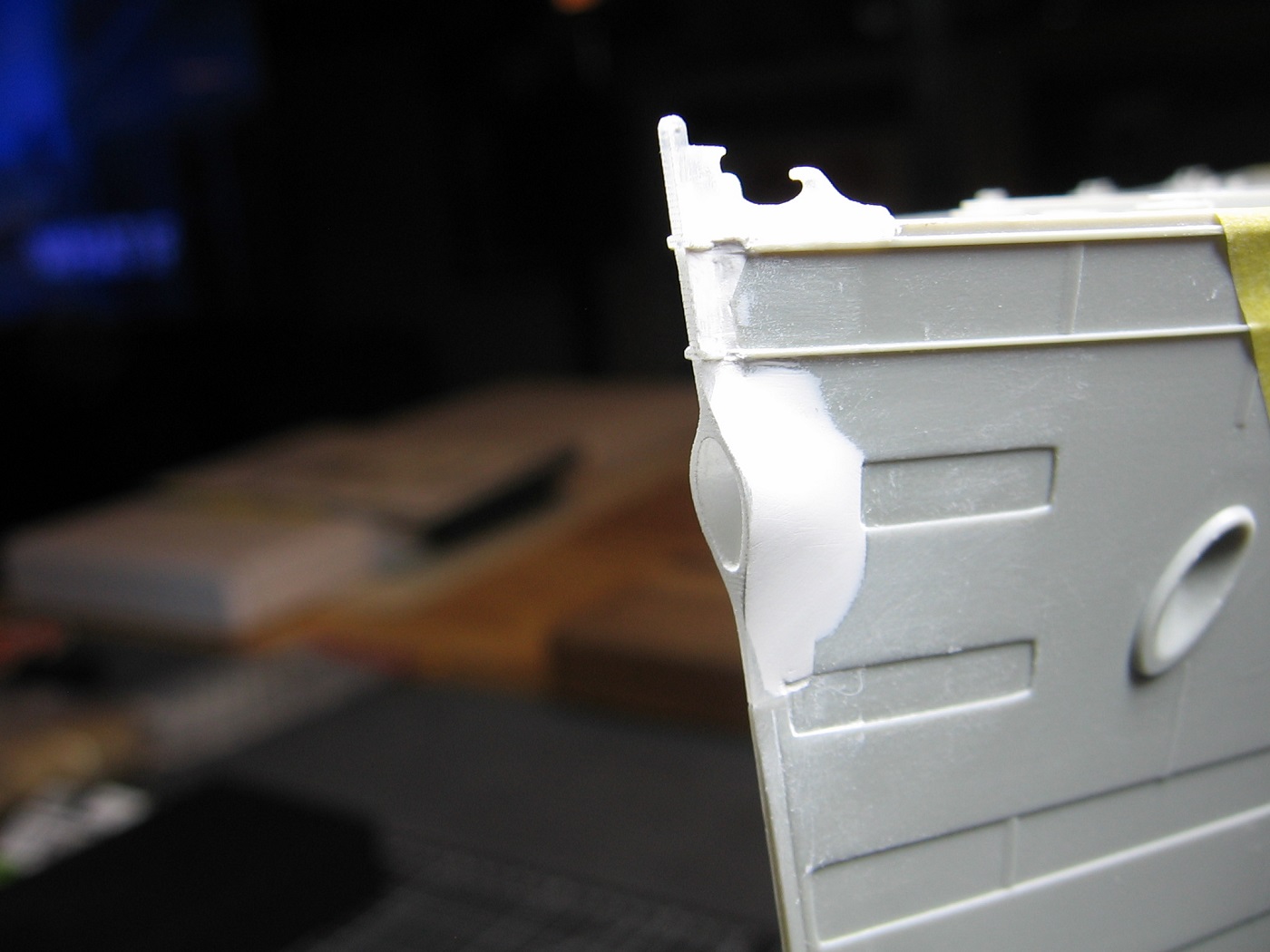
I began with Port Forward. The KA instructions indicate a door goes here (red circle).
It is also “implied” (my term) from the Starboard profile hull plating diagram in a particular reference book, that there should be a door here (again, red circle) so I attached a KA door here.

As well, it appeared to me that some other modifications were required. The raised feature within the blue circle is not in said diagram and needed removal. Further, the lower portion of the raised feature within the black circle needed to be trimmed.
Here’s an image of the work done.

But wait! The KA instructions are wrong, and the hull plating profile perused is that of the Starboard side, not the Port side!
I forget the sequences of events moving forward from here, but upon researching the doors more I discovered the following:
-
There are instructions for MiniBrass’ Hull Plating PE sheets (who knew?). I was previously aware that MiniBrass has these sheets available, however I had assumed that using them requires major plastic cutting surgery. After reading through the instructions (that I just discovered), it looks to me that the application of these is not as hard as I originally thought. -
Also discovered in said instructions, apparently, there is no such door on the Port side, such as what I just applied. -
Unfortunately, there is no Port profile hull plating diagram in the (to remain nameless) reference book to point this out. -
 However, perusing a photograph in another reference book confirms this. No door here (red circle). Looks like I got the other modifications wrong
 as well (blue and black circles).

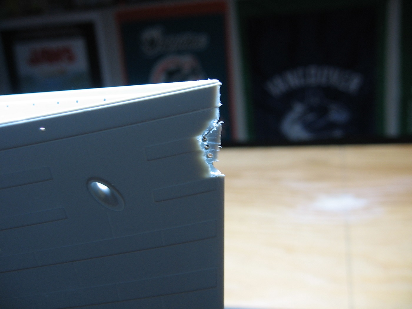
Also, while working on this door application I couldn’t help but notice (for the umpteenth time) the rivet damage I’ve incurred to the hull prior to having the cradle I have it in now. Prior to the cradle, I just had the hull on two boards with hand towels as protection. It didn’t always work out. Not to mention some of the rivets were inadvertently chiseled away by carelessness while chiseling something adjacent. Sometime a go, I purchased an HO scale 3D rivet decals sheet to help rectify this, but they just aren’t the same.
Taking into consideration….
-
the rivet damage…. -
that the Trumpeter hull rivet detail is actually quite lacking overall and that the MiniBrass PE kit captures the actual rivet detail…. -
that the MiniBrass kit looks to be not that difficult to apply….. -
and the MiniBrass kit should take out further guesswork of what goes where….
I’ve decided to order the MiniBrass 200 Hull Plating Kit.
In the meantime, I’ve applied the Trumpeter provided PE parts 48, 49, 50, and 51. Condenser Intake screens.

Next work will be on the Prow Hawser Port. This piece was purchased from Shapeways.

This will require some plastic surgery and putty/sculpting application. Intending major patience on this. Even if the first cut takes me an hour, it takes me an hour. Hoping it goes well.
Hopefully what I’ve described makes sense. Believe me, to achieve an accurate representation of the Titanic with this kit is a major challenge and I’m often lost myself. I can only image the experience of what others just reading about it is.
Thanks for looking. Suggestions are welcome.
Cheers,
Mark
4 Likes
I don’t have suggestions as what you are attempting is way out of my area of expertise. ![]()
The level of detail you’re aiming for is mind blowing. ![]()
What I can offer is that I’m rooting for you and think the job you are doing now is spectacular! ![]()
Enjoying the process immensely. Thank you for sharing it all!
1 Like
Your attention to detailing is amazing with this build. To build one of these 1/200 ship kits is definitely on my “Bucket List” of modeling projects.
@MR_TOM_SCHRY Thanks Tom! It’s a big project. I expect this build will take me another 3 years to complete. Mind you, that’s doing other projects in the meantime as well.
Cheers,
Mark
The Prow Hawse Port.
Used for the center anchor as well as being towed from ahead.
It did not look as Trumpeter molded it.

I began with filing down Trumpeter’s version. Not sure if that was necessary. It might have helped keep the saw in line.

I used a #13 Excel saw blade for the cut. I cut down 25mm. This was conservative, making sure I didn’t cut too far, and fined tuned later.

The gap here, on the Starboard side, came away pretty much on its own. For the Port side I had to do some additional cutting. The first additional cut was easy. For the second additional cut I decided to drill holes to make the turn easier. I suppose, in hindsight, I could have made that cut coming up from the bottom instead.

I measured the gap required to be ~0.75mm wide. Using a file to accomplish that width.

Cutting complete. No turning back now. I put the Fo’c’sle deck in place to ensure no fit issues down the road.

The new Hawse Port CA glued in place.


I used a straight edge to ensure proper alignment with the stem.

The next step was puttying. I first taped the exterior of the gaps, to act as a backstop, because……

…. I applied putty from the interior first.

I let this set for 24 hours. I used Milliput Superfine.
As expected, some putty was pushed through to the exterior. Port side as well.

Milliput Superfine putty applied to the Port side. Let to cure 24 hours. The red arrow indicates a piece of styrene strip I taped in place. I neglected to take a picture of this prior to puttying. Purpose of this was to let the putty create the forward edge of the recessed strake here, as opposed to me trying to sculpt it later.

Post sanding, Port side.
Starboard side. Blue arrow in this image better explains the intent of the styrene strip. Red arrow indicates the Mainmast Forestay fitting. Note that it is intact.

I flipped the hull upside down to work on the Starboard side. I’m right-handed and wanted to sand from aft to forward, for the most part. My main concern with this was that I hoped the different perspective wouldn’t cause a different result.

Starboard side putty in place. Let cure 24 hours.

Starboard side sanding complete (for the most part). Note the red arrow indicating the now missing Forestay fitting. While the hull was still upside down in the cradle, I decided to do some clean up and clipped it with the hand vac. Downside to many resin parts. Very brittle. Spent about 20 minutes looking for it.

Next task was to fill these gaps (within the red circles).

And filled. For the top ridge I used 0.75mm x 1.0mm styrene strip, sanded down to ~ 0.55mm² prior to gluing in place. For the bottom gap I used 0.25mm x 0.5mm strip.

The ridge gaps on the Starboard side were not as bad and did not require styrene. The camera shows me they still need attention, however, so I’ll take another look at those.

New forestay fitting manufactured from 0.75mm x 1.5mm styrene strip. The hole is 0.7mm. Larger than the original hole, but it’s the smallest drill bit I have. Probably should have left this well enough alone until much later. No doubt it will get broken off again. Note to self: Be careful.

Some final shots. The last one shows the cover in place.


It’s not perfect, but disaster averted. This could have gone so wrong. I’m very pleased with how this turned out.
Thanks for looking.
Cheers,
Mark
7 Likes
That …was quite a bit of work Mark…but well worth every second of it as seen in the ending results. I’m looking forward to see what other modifications you’ll be putting into this build along the way as I’m pretty sure that this isn’t the only area of this model that will need the “Mark treatment”.
Yes, it was worth it. I still need to fine tune the Starboard side with a sanding stick, I believe.
I don’t foresee anymore cutting required in the future, but we’ll see.
I will have to do a significant amount of sanding in advance of another PE AM kit I have on order. Need to chisel and sand off some features that the PE will be replacing.
Thanks for looking and commenting, Joe.
Cheers,
Mark
1 Like
Hopefully you won’t have to keep doing many more mods like this to get the kit to where you want it. I’ve had kits to where one mod lead into another …and then another…and then another to make things work. Tuned in to what’s next bud.
1 Like
You should be. That’s really well done – talk about confidence, taking a saw to such a conspicuous spot!
2 Likes
Thanks Tom. Actually, I purchased that little AM piece with the idea of just using it as a visual guide for puttying and sculpting the correction, but then decided what the heck, I’ll trying putting the actual piece in place. So happy I was able to pull it off.
Cheers,
Mark
1 Like
Outstanding work on this bow scratching project. You really did an amazing job of blending that into the existing hull.
1 Like
Thank you, Tom. I’m very pleased with it.
Cheers,
Mark
For the second week in a row, I am humbly honored to have a WIP of mine featured (link to) in the current FineScale Modeler Newsletter email. This time my 1/200 Trumpeter Titanic build. Thank you FSM!
Having said that, this build is on hold while I work toward wrapping up my Phantom of the Opera build. Hoping to have an update here soon.
Cheers,
Mark
2 Likes