I am starting a model on the USS Monitor using a 1/96th scale resin kit. Right now I am in the information collection phase. My problem is I intend to model the interior viewed through cut aways. While there is lots of information on the exterior of the ship, there is little on the interior except the major equipment like the engine and boilers. In order to place things correctly I need the minor details so I wanted to pick other’s brains for info they may have collected over the years or potential sources. Of course the Martime Museums restoration is a major source especially for the turret, guns and engine but not much on other details. What I am looking for is the more bland information. For example, it is easy to find out the deck armour thickness, it’s 2 inches. But I need to know the clearance under the deck for the interior. So I need to know how the deck was installed. Did it have a wooden flooring between it and the beams supporting it? How thick is the flooring? What is the size of the beams? Likewise the floor of the interior is raised apparently at least three different levels. I need to know how much since this is all subtracting from interior clearances which will become critical when “scale” sailors are put into the cutouts.
Have you done an image search? There seems to be quite a lot there, and as always you can swim upstream to the source once you find something.
Bill
Oh yes. There are 40 to 50 images plus various interpretations by other modeler’s who have posted pictures. The problem is most have no dimensioning and none are from original plans. Some drawings appear to show a subflooring to the the iron plating on the deck and others don’t. Also the supporting beam cross section varies between square and rectangular (some in horizonal some in vertical). My understanding is that the original plans of the Monitor have do exist but I haven’t found them online yet. Parts of them have been reproduced but usually without dimensioning.
What I wish I could find is something saying like deck was iron plate 2" thick attached to cross beams of 6x6 oak spaced every 18 inches.
Also, very few address the fact that the deck is sloped for drainage. As far as I can tell there is no center beam so the cross beams can be sloped so how did they do that?
Even armor thickness on the deck is open to question. I have references saying 2 inches but also one saying it was made by two layers of 1/2" wrought iron plate.
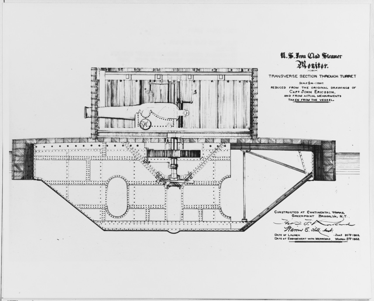
From the Naval Historical Center (history.navy.mil) Several drawings available. While not totally dimensioned, this drawing is scaled. Take measurements off a known object (cannon, turret) & transfer measurements to unknown.
Another source will be the US Archives in College Park, MD. They have several original drawings on linen. I have personally handled the Miantomah. If unable to get to the Archives personally you can hire a researcher to do the leg work.
I have a copy of that image but yours has much better resolution. Unfortunately, the scaling isn’t usable since its a reduction copy. But it does look like it has enough detail I can use the turret dimension to calculate some of the others. This image looks like it did have a wood layer under the iron plate and that the cross beams are being used to create the slope. Unfortunately, I can’t tell what the cross beam material is. Since this is the section under the turret those beams could be iron rather than wood to help support the considerable weight of the turret. Unless they relied on the metal bulkhead under the turret to provide that support. Being in Texas kind of limits my access. I suspect the Virginia Maritime Museum has much of the information I need but the combination of distance and virus may not make that an option.
Lightfoot,
I highly recommend you contact the Mariners Museum. They have the plans.
https://www.marinersmuseum.org/library/plans-drawings/
I am currently discussing offline with several members here about the new Micro-Mir 1/144 kit of the Monitor and its “issues”. Although it is not relevant to interior layout, the external features of the Monitor and details from the various plans may be of interest.
I have a PM on the way.
Nino
P.S. As I go thru the available info I will confirm what Plans, Pictures, Reports can be posted here and I will Post’em!
P.P.S.
What you really need is this.
https://digital.ncdcr.gov/digital/collection/p249901coll22/id/397371/

Unfortunately, they make only some of their plans available online. I subscribe to their Blog in case they give more detail but I suspect the only way to get the kind of plans I need would be to go there. Mostly their online information concentrates on the metal parts of the Monitor they have recovered (engine, guns, turret, etc.).
Try this link:
https://digital.ncdcr.gov/digital/collection/p249901coll22/id/397371/

The PDF file is 42 MB. The scans of the plans are mostly readable. It’s the descriptions that are the most helpfull. There are over 500 pages.
Check out the original design of the Monitor below. Looks like a UFO.
Nino

Drawing courtesy of “Drawings of the U.S.S. Monitor: a catalog and technical analysis” from North Carolina State Publications.
Thanks, this is what I needed. Actually found the book still in print in England on Amazon. May still need to see if I can find some of the drawings in high resolution copies to be able to read the detail.
You’ll recall that Museum was the museum that Dr. Tilley worked for. He helped me model the skylight of the America, which he worked on at the Museum. Great resource.
Bill
I have a book titled Monitor by J F deKay, but the drawings are the same as others have posted. I am not sure what you have against online drawings. Can you not download them and resize them to whatever scale you want in a graphics program?
Also, isn’t the engine and mechanical systems what you need for interior detail?
Also, doesn’t the section view posted by Ed Grune answer the questions about the deck thickess and space?
The problem with reproductions of drawings in books are the loss of detail and dimensioning reference points. There is further loss when they are scanned by someong for posting on line. By the time the reduce the original down to a size that will fit on a printed page you are lucky if any writing on the drawing is readable. Most of the online images I have downloaded are less than 800x400 pixel which on many of them make 1 pixel = 1 foot. The best cross section I have is 1280x1030 but it has no dimensioning data in the drawing. I can come close by trying to create a scale matching turret diameter but I am hoping to find a drawing that has a printed scale to verify the size with. Or better yet a construction report for the Monitor saysing what size blanks were used.
I need to get the decks correct because in a cut away they will be in full view. One of the most detail cutaway models I have found pictures of don’t show the flooring at all. Just the metal plating attached directly to the beams.
The Engines, Boilers and other large equipment also need to be modeled but there is considerable published information on them. Although, the Boiler diagrams have errors in them. Those I will model in Fusion and 3D print.
Under flooring is another area that there is little information on. It is shown only as lines in most drawings. Hoping to come across something detailing them.
But the best results come from an original document scanned at high resolution at its full size. Then you can search for detail by magnifying and you can print at its correct scaling for making measurements.
I wish you luck on that because they may not exist.
I can tell you, having drawn buildings for a living, that up until 3D modeling became common, drawings generally were meant to describe the general arrangement of something. The actual dimensioned drawings of her frames, longerons and other components most likely were done in chalk on the lofting floor.
We restored Grauman’s Chinese Theater in Hollywood back in the early eighties. We were fortunate to have the original drawings and we scanned them, but they in no way were to scale. And those were from 1920 I think.
Looking at Eds drawing, I see a lot of wood with metal plating over it.
I suspect a lot of things were done by point and do. “Run a pipe from here to there” type instructions. I have that problem with the Boiler. The ship has two steam driven ventilators on the rear. One is used to force air through the ship for the crew. The other is suppose to be a forced air blower for the Boiler furnace. But so far I haven’t found any indication of forced air entering the boiler unless it is just a general system to increase the air pressure in the engine room and assume it goes into the fire box as opposed to a true forced air system where the air is piped into the back of the fire box. Doesn’t help that the Boiler drawing have numerous errors.
But I am making progress on the wood specifications. So far:
Under Iron Plated deck: 6" x 12" (although this is by interpolations of drawings)
Beams (actually specified): 10" x 10" (although a few special ones 12x12)
Flooring (of cabin areas): 2-1/2" x 9"
Now to see if I can find precut veneers and bass wood in those sizes at 1/96th scale. This use to be easy when places like ModelExpo carried a full line of ship fittings and woods. You could order veneer strips in a wide range of sizes and wood types.
That’s a fact. I have a table saw I bought at Micro Mark when they had a 20% off sale. A little over $ 300. One thing it doesn’t do is produce strip wood in quantity quickly, but yes I can pretty much make whatever size I want in a wide variety of species.

Worth saving up for.
Hi;
Just so you know.The boiler room being somewhat pressurized would help get a better burn in the firebox. Now, that said they didn’t have boiler casings like they did after the Fletchers. So, after those ships and their types, the fire-rooms did Not have to be pressurized.
Hi " G"
I ran into the same problem at Fort Roots.( A V.A. medical center in North Little Rock, Arkansas) , years ago, They wanted a building returned to it’s “As Built”( 1853) appearance on the outside and modern inside.
The biggest problem was that we had to measure everything by hand. We didn’t have Laser equipment till three years later. So we had to hire a Surveyer!
It came out alright though. A fun project at that! I was working for Cromwell, Levy Truemper and Gatchell, Architects and Engineers as a consultant. I had done two earlier for A group in Tenessee under contract.
Since it states that the ship does have a forced air ventilator on the rear of the ship, I am pretty sure it is using that to move air through the firebox. In free standing steam engines this would be actually routed to the firebox by pipes. But it also usually required a mechanical means of putting coal into the firebox since openning the front to shovel it in would result in fire being blown into the engine room.
My suspicion is that the ventilator just forces air into the Engine Room using the center bulkhead to restrict air flow so that a few inches of water pressure would be created in the Engine Room/Boiler area. Then air would be forced through the openning below the coal grate in the Firebox and through the boiler to the stack. That type system wouldn’t require special piping. I have just got to find a way to confirm my assumption.
There is a view of the rear air vent depicted in a Congressional Serial set of published docs on the Monitor. There is no pipe. It seems to be open to the engine room spaces below. I can not tell if it is Port or Starboard.
So, is Air is simply drawn into the engine room to create positive pressure? There is a mention in the remarks on page 176 about air to the forward part of the ship was from the Starboard blower. Hope this helps get you on the right path.
EDIT: In the top drawing the long thin pipe overhead I BELIEVE TO BE THE “waste” or Excess Steam pipe . You will need that location too. Looks like this drawing may be the condenser rather than a blower motor as it has a small “device” on top which is likely the escape valve to release presure.( Note: this valve is operated from the deck by removing the grating.) Note also that the condenser has what looks like a pipe running to the right and up to the overhead and forward. I did not find the next photo showing the forward part of the engine room which might show the termination of this pipe. I will keep looking.

A sample link of some Congressional Series Docs.
It takes awhile to find details on Monitor and Virginia in these congressioinal records but there is a wealth of personal experiences and obsevation in this series.
P.S. In the USS Monitor Drawings and Plans book referenced in my earlier post there is a nice drawing of the engine room components on page 358 and other nearby pages. Read The Remarks!
That’s a good drawing of the bow and stern. Wish I could find similar for each section of the ship. Unfortunately, they rarely combine both a side and top view so you can place things in three dimensions.
The Starboard ventilator forces air under the floor. I haven’t found anything showing how it gets it there but under the flooring there are holes through each floor support to route the air to the forward part of the ship where it comes up through floor vents. But this sort of thing other than the unidentified pipe to the floor wouldn’t show up in my cut outs.
The forced air blower to the Boiler is more important because it will alter how the the boiler is depicted depending on whether it gets it air from the room or a pipe.
I am also surprised I am having so much trouble finding details on how the turret was rotated. I can find drawings on the two donkey engines used to power it and I can find a cross section showing the gear on the pipe supporting the turret. But nothing shows the gear set up that transfer power from the donkey engines to that gear atttached to the turret. Also, it isn’t clear how that pipe is supported. That just doesn’t look like any kind of bearing and load support under it that would handle the weight of the turret and guns.
I got your link to the Congressional Serial set. Have to see if I can figure out how to find things.