Also came across references to the Plastic Modelers Club who did some detail collection of drawings for their member who wanted to build the Monitor. But apparently they no long exists or at least Google can’t find them.
I would be quite certain that the central axle didn’t support the turret. It’s just too heavy and that would concentrate the load in one place.
More likely, the turret rested on it’s ring. What that bearing, if that is the case; looked like I don’t know, but it might be two flat surfaces with grease.
Elsewhere there’s reference to two donkey engines and four gears.
Bill
[/quote]
Apparently it only rested on the ring when not in use. There was a wedge under the spindle used to lift the turret off the ring about 1.5 inches so it could rotate.
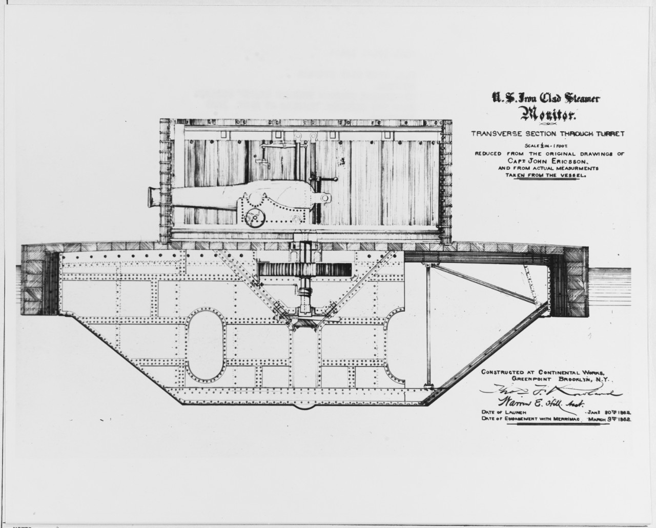
"Including the guns, the turret weighed approximately 160 long tons (163 t); the entire weight rested on an iron spindle that had to be jacked up using a wedge before the turret could rotate.[37] The spindle was 9 inches (23 cm) in diameter which gave it ten times the strength needed in preventing the turret from sliding sideways.[38] When not in use, the turret rested on a brass ring on the deck that was intended to form a watertight seal. "
But like you I don’t see anything in the drawings to indicate how they stabilized the turret once it was lifted or how the ship’s hull could support 160 tons of weight through a 9 inch spindle. I don’t see the kind of supports under it or through the deck beams that would hold up 160 tons.
Knowing there are four gears will help. Now to just figure out there relative size and arrangement. ![]()
I did not come across any turret mounting/rotating info beyound what you seem to have. I did look thru The Monitor Centers Twitter postings and photos and found a few interesting pics. These are Courtesy of the Monitor Lab…
Take a look here for the Twitter feed . It has many photos .
https://twitter.com/USSMonitorLab
The Floor of the engine room. A nice diamond pattern.

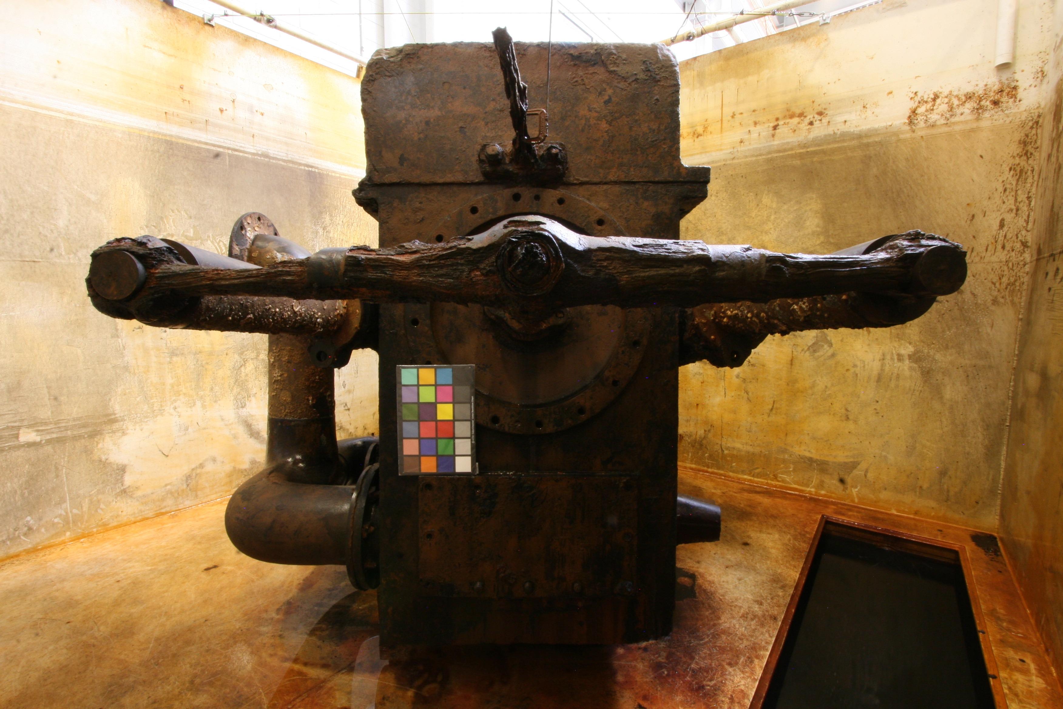
The real Condenser:

That Turret… When they first pulled it out and got photos of it somewhat drained, I remember trying to count the metal slats in the turret roof. I came up with 36 (or a possible 40*(edit)*- it was real muddy.) These slats appeared to be at least 4 inches apart so I am pretty sure there was another roof on top of that for the sailors to walk on. I had posted a question to the Mariners Museum staff as to what they believed it looked like. I have not heard back.
Have fun!
Let us know how you are making out.
Nino.
Thanks for the twitter link, I’ll follow that and see if something new pops up. The top had a grid of beams which allowed ventilation as well as a floor for those on top. But it doesn’t appear to provide much else. There are some supports coming up from the sides of the floor to the center column. It just doesn’t appear strong enough to help support the turret at the top which would be more stable than at the bottom. I keep looking for something that would keep the turret stable when it was in the lifted position for rotation. Normally you would expect wheels around the bottom like they used on guns that had to rotate. Maybe more weight was carried through the top of center pipe than the two braces would indicate.
Looks like that center post is what raised’er up. Bet the guns had to be restrained back to a loading position for balance.
Do you suppose the crew had to make like the U-Boat crews when diving as in “everybody LEAN this WAY”!??
The Monitor Turret replica only shows the center support. The adjustable rods that were added for floor suppport will stop the floor and roof from deforming during lifting so it would appear they expected the center support to have the weight. (Note 2 angled support rods over each Gun to compensate for the extra weight compared to single rods for and aft!)
When asked “how does it work”, maybe it’s a bit like the Special Project subs, Seawolf & Parche. The answer: “Very Well!” Okay, maybe not all that well. There is evidence that the turret was not, (Could not be?), aimed directly at the target but was trained in the expected path of the Virginia and them fired “as she bares”.
As regards a 9 inch shaft to lift the turret… (I wish…)
Enough joking… The Replica Turret:
Link:
https://www.facebook.com/marinersmuseum/photos/a.10150228208175402/10156509583715402

credit:
“The USS Monitor’s revolutionary gun turret. This replica perfectly depicts John Ericsson’s innovative design”. Photo by Kurt Fanus.
Nino
Edit: That Turret roof support on the Replica is NOT exactly accurate. Should be 4 Supports across the entire turret ( They left a section out.)
A few more things of interest…
There is a group doing 3D renderings of the Monitor artifacts.
ink: https://sketchfab.com/NOAAMonitorNMS/collections/uss-monitor-virtual-artifact-collection
“This is a laser scan of USS Monitor‘s iconic gun turret taken in summer 2016 by API Services of Newport News, Virginia. Because this is laser scan data, versus the photogrammetric models seen in the rest of this collection, there is no photorealistic texture for this image. Having data like this available, though - accurate within centimeters - means that we can now study the construction and use-life features of the artifact while it is still submerged in its conservation treatment bath at The Mariners’ Museum and Park in Newport News, Virginia.”
The Turret:
link: https://sketchfab.com/3d-models/uss-monitor-turret-51c24ab1647646c0b820767dfc892aea
My Observation:The Turret roof was a flat perforated surface overtop of the 40 , (or 41?), iron slats (railroad rails!), that were supported by the 4 iron Joists. Now we know!
The Condensor:
Condenser link: https://sketchfab.com/3d-models/uss-monitors-condenser-0b7a0a7b569e408886f7174e3c46527a
Note that this 3d render of the Condenser is UPSIDE DOWN!
Nino
Interesting 3D, unfortunately not downloadable. Curiously, I now have found two methods describing how the lift worked. One from the original plans for the monitor show a wedge about half way up the central column in the hull of the ship. It supposedly lived the 9" pipe supporting the turret about 1-1/2" so the edges wouldn’t touch and it could rotate freely. However, the model I purchased from Cottage Industry has a lifting bar inside the turret which lift the center pipe and turret by leveraging it with a screw at the side of the turret. Based on the pictures and 3D the turret was supported through the center with supports spread out to either end of the gun rails. But neither show the mechanism that was included in the model. Or, for that matter, show the 9" pipe extending to the top of the turret.
Some of the images enlarge and “I suppose” all can be copied using a “Screenshot”.
(Quality is good as I can count the holes in the upper deck perforations.)
Too bad they did not recover the rotating mechanism or at least a few gears.
Nino (Jim)
As for the boiler, just a thought. With the room pressurized, the air is controlled through a register in the boiler front, probably located in the coal door, where they shovelled in the coal. That way, they would not get a flare back through the register or the door when they opened the plate to feed. Air flow would be fairly consistant.
The process would be something like ‘open the register all the way then open the feed door, feed in coal, close door, then adjust register for correct burn.’
From the drawing I’ve seen, the boiler appears to be a fire-tube unit rather than a water-tube, So we are talking low pressure, saturated steam.
Like I said, just a thought, having operated boilers in the past.
One more thing regarding the turret. As the ship moved through the water it would rock side to side and front and back. This movement would cause the turret to move laterally. I don’t think that the central shaft would be strong enough the keep the turret from sliding off of the main deck. Once the heavy turret developed lateral momentum it could snap the central shaft. If you look at the cross section of the turret at the top of this post it looks like the bearing located under the exterior wall of the turret is recessed below the top surface of the deck. That recess would prevent any lateral movement of the turret. A simple yet ingenious solution.
Just an FYI…
The Cottage USS Monitor shows the hulll armor overlapping the hull side armor. In at least 1 photo it appears that the hull’s armored sides went all the way up and the deck plating did not cover the top edge of the armored hull sides.
Cottage 1/96 kit example showing edge of deck overlaps the hull sides:
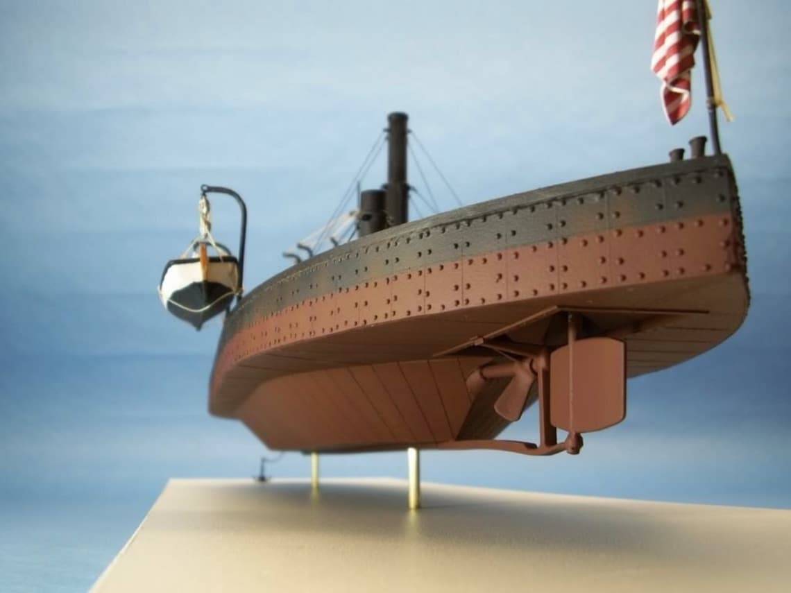
Photo of Hull side armor to deck plating contact:

Note the crack in the deck at the lower right corner. Some believe this to be the result of contact with Virginia’s bow stem.
Hull armor seems tp go all the up to the deck edge. (Same photo as at the start of the thread):
For those interested , take a look at this link for a nice drawing of the engine, bilge pumps, etc., with extra descriptions:
Nino
Edit: Try this link for more on the Turret rotating engine:
http://www.shipmodels.info/mws_forum/viewtopic.php?f=27&t=66949
The last picture shows the lift mechanism which was a wedge with a bolt to move it in and out. It could lift the turret about 1-3/4". I contacted the person who made the kit. What he labeled in his construction drawings as the lift mechanism was really the controls for engaging the the gears that turn the turret.
Nino is right on the deck althought the top armor plate may go all the way to the edge. The wood under deck didn’t.
When the ship wan’t in battle the turret sat down in a recess groove to make it water tight. But it couldn’t move in that position.
Trying now to better define the pedistal the 9" pipe with the wedge under it is sitting on and how it connects into the center bulkhead. It isn’t clear in the picture above. It shows it in the center of the buldhead but I haven’t found a crossection looking form the side of the ship that I have confidence is correct. Some show it cut flat on the bulkhead side.
Better (??), Larger picture of side view. Maybe this resolution can help.
It does appear they left off much of the mechanism in this drawing. At least what is there is said to be from measurements of the actual ship.

Click on it to see the larger pic.
Jim.
P.S. How 'bout that Anchor mechanism!
Thanks Nino, that is a much better resolution than I have on other drawings. A lot more detail added too. Actually shows how the rudder is connected to steering. That has been my trouble with published drawings. They are all low resolution scans of the originials. In Peterkin’s Catalog of drawings he sometimes describes things in the drawings that you can’t see but it is like they say “a picture is worth a thousands word”. But I do wish these people believed in adding scales to legend so you can measure things in the drawing. In the Catalog’s reproductions they say what the scale is (like 1" = 1’) but because it is a reduced reproduction it is meaningless.
Pretty sure you must have come across this video of a " Monitor engine".
https://www.youtube.com/watch?v=VWn8gQ9Ykpk
And the real one: https://www.dailypress.com/resizer/0Kk16l4KUm7EGBAwQcg70dkY6JM=/800x534/top/arc-anglerfish-arc2-prod-tronc.s3.amazonaws.com/public/6PFQ3MA74ZBMLPFUJJ7ICFRI54.1

You might want to hop onto Facebook as the Mariners Museum folks have been answering my questions on Turret roof details. Perhaps you can post a querry about rotating that turret.
https://www.facebook.com/marinersmuseum
Jim.
Nino: What did they say about the roof? I have multiple references giving the roof flooring as iron bars, triangular iron bars (in Erickson’s original drawings), and railroad tracks (which I favor). I find facebook pages the most difficult platform for useful information. It ages off to quickly and has a very poor search mechanism. Forum format is much better for accessing information.
It’s probably correct to think of the movement of the turret as a way to choose what angle to the direction of travel the engagement would be made at. Sort of like the centrally mounted large guns on Kearsarge and Alabama.
Not a set up where the ship could move it’s fire to multiple targets.
I’m guessing here.
My response from the Mariners folks to that very question:
Hi Jim,
The outer roof of the turret consists of 14 plates with the central 6 perforated; under that, is railroad track followed by large wrought iron beam.
https://sketchfab.com/3d-models/uss-monitor-turret-51c24ab1647646c0b820767dfc892aea

My notes are anotated on the Monitor Centers 3D rendering above.
(Image Provided by Sketchfab.com)
(The hatches did slide on the depicted rails, to the Rear not to the Center.)
Here is the actual make-up of the Turret roof:
(The hatch openings are conjecture on this older rendering)

( An update to the drawing above… The right rear hatch in the Turret deck was the only one that accessed the lower deck. The turret had to be turned to line up with the “hatch access” below.)
I had known about the Iron plate perforated roof but had no proof till they confirmed it. The one thing I did not ask is whether this roof is due to the refit after the March 9th 1862 battle or was it always like this.
Those railroad type rails were listed as on 6 inch centers. Placed upside down with the largest surface to walk on, I suspect the space between the rails may have been only 2 inches so they could have been the roof on the day of the battle and the iron plates with the Perforations may have been added during the refit with the Pilot house and Stack changes.
I would not doubt that a wood slat deck could have been intended for the roof to lay on top of the 40 (Or 41?) iron rails instead of the iron perforated plates but the Monitor had to get to Hampton Roads ASAP and I bet a lot of stuff was not done.
one other thing…
Heck, talk about a rush job…they only had bilge pumps in the stern so a “Bilge Keel” was made part of the hull bottom so that water in the bilge could flow from the bow to the stern. All the models of the Monitor leave that “curved” hull protrusion out.


Those plans can be downloaded from here:
https://archive.org/details/drawingsofussmon00pete
Several formats are available.
Jim.
I neglected to add in a link for a very well done review of the Sinking of the USS Monitor. It has descriptions of some of the changes during the re-fit in October 1862 including raising of the main deck by 3 feet in the wardroom area.
Halfway down the page you will see this:
There is a Button to download or read the entire text of the investigation.
Nino.