Here are some interesting 3D printing factoids. Space X’s new Raptor 3 engine prototype uses 40% 3D printed part by mass. The Intuitive Machine’s Odysseus moon lander has a 3D printed part in the upper section of the engine nozzle. The astronauts on the ISS are playing around with 3D printing in space using stainless steel filament. If you are going on a multi-year trip to Mars how many spare parts do you bring? You can’t just send more parts if you break down. Instead of hauling tons of spare parts, why not bring a 3D printer and spools of metal filament to make whatever part you need on the way?
I’m ready to final print the side 1 pipes but what color are they? The vent lines are all the same grey as everything else. Looking at pictures of side 2 and 4 the supply lines are white. On side 1 the LH2 supply lines are white but the valve complex looks to be grey. What I have been struggling with is the LOX supply lines on side 1. They are not white but in some pictures they look to be a few shades lighter than the grey. This may be due to shadows. Colors are really hard to determine in pictures since they change quite a bit depending on the lighting conditions. Are they silver or aluminum? The LOX/LH2 lines on the Saturn V LUT were all white so white makes sense. Is this insulation? Liquid hydrogen has to be at least -252.8 degrees C which is really cold, 20.28 degrees (or colder) above absolute zero. It turns out they use a pipe within a pipe as insulation with a vacuum between the pipes. This limits the three forms of heat transfer; convection, conduction and radiation. Maybe they used white paint to reduce solar heating. Not sure why they changed the color of the LOX pipe on side 1 but I will go with grey.
The side 1 LOX pipes are complete and published. There is a mix of filament and resin parts. The smallest pipe going to the tunnel would be dicey with filament and the relief valves would be all but impossible. Here is a picture of the main valve assembly printed with filament and resin. I like the resin a lot better.

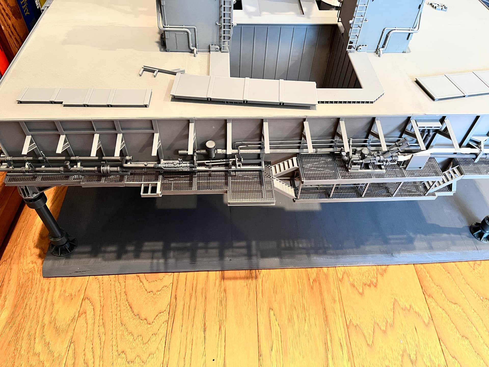
Here are some overall pictures.


Now I am working on side 2. There are some things to add before finally adding the LOX pipes. First is the gutters since they have downspout pipes that go being the LOX pipes.

Near the middle is an MLP to SSAT interface. Once parked and on the piers, there would be a structure with stairs that you would use to access the top of the launcher. This is where the structure would connect, including a grate that goes over the gutter. This grating is the smallest, most delicate part I have made with the resin printer.


The other parts I have added are the pneumatic mufflers. These were on the Saturn V launcher. I have included a filament version and a new resin version with the grating on the ends.

Here are the LOX pipes going the length of side 2. You can also see that I painted the electrical interfaces with a rust wash. The pipes angle down on the left side just a bit.


1 Like
Side 4 is complete. This side has the LH2 pipes going to the side 1 valves. This also includes vents and a platform interface. The bottom vent pipe angles down on the right side. As with side 2, the gutters should go on first.


2 Likes
Everything looks great. I’m assuming you’re close to the finish line. Looking forward to seeing the completed stack.
Yes, I am close, probably within two months. After finishing the launcher I need to finish up the crawler by adding the interior equipment. About 3 years ago I set it aside since at least two other people were adding interiors and I was hoping they would publish their parts. That hasn’t happened so it’s about time to research the innards and design parts.
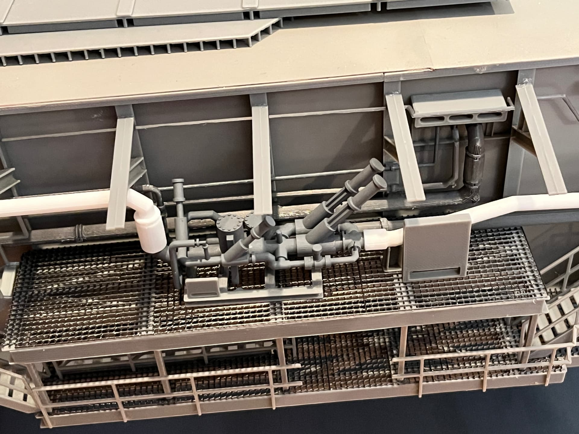
This is the most complicated part I have ever drawn up, the LH2 valve assembly. Every time I look at pictures I see something else to add. Without a doubt, the majority of this will be a resin print. I will separate the I-beam structure it sits on and print that with filament, then decide where and how to connect filament pipes to this structure. For the supply pipes, they are white so there are logical connection points. The main vent pipe is the large one towards the back.

Here is the valve assembly hot off the printer. The platform was filament printed as a separate part. There is also a picture of the valve assembly roughly in place with the white supply line attached for now. The valves still need to be painted.


1 Like
It’s amazing how far 3-D printers have come. Part came out nice. Interested in seeing your crawler.
Thanks. Yeah, 3D printing is just as good as the plastic model parts. I have even noticed other people selling resin printed parts as add ons for kit models. I am also working on a 1/200 scale USS Missouri with all the photo etched parts. Some parts were not available so I 3D printed them and made them available for others. I will complete the crawler once I finish this one.
The LH2 pipes and valves are installed along with some control panels. Before adding the pipes to the tunnel where they go into the launcher there are some parts that go behind them including sprinkler pipes and the overhead blast shields.


2 Likes
Before the sprinkler pipes can go on, the blast shield supports should go on. I used the blast shields to determine exactly where the supports should go. The long center shield goes just under the top lip and the left shield should line up with the extension already printed in the side panels.
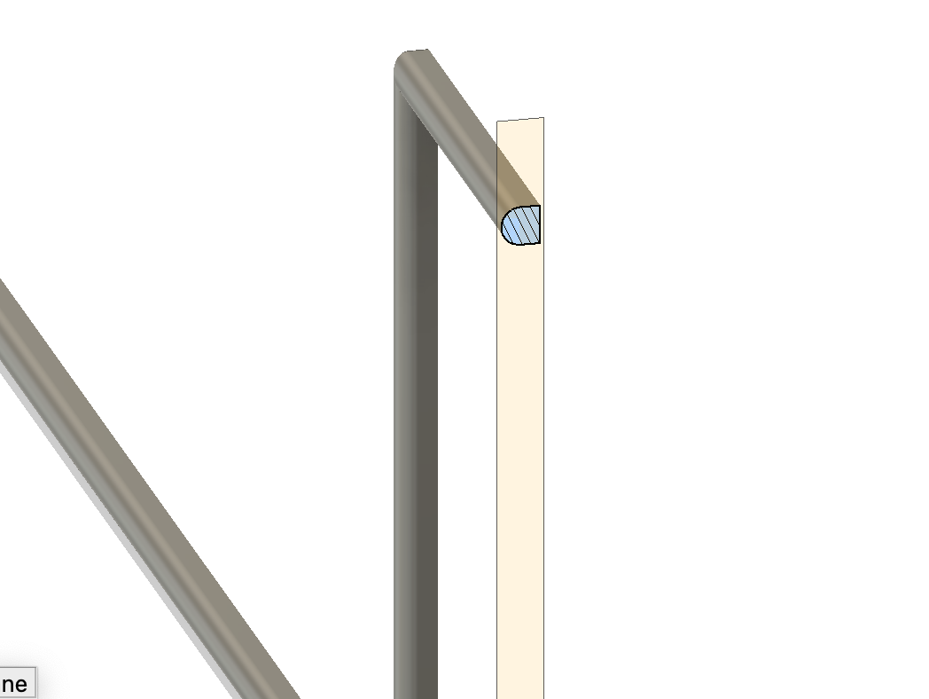
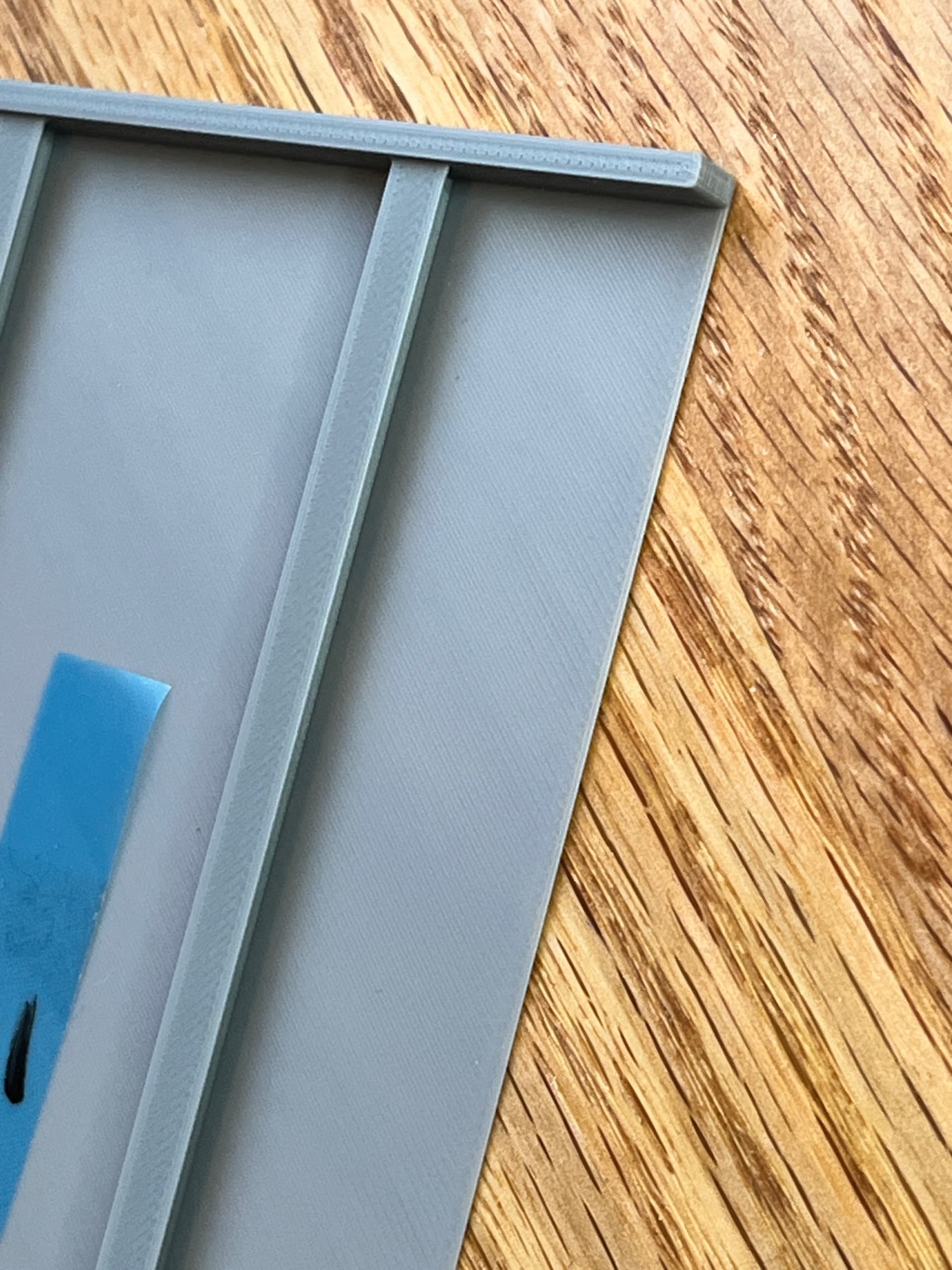
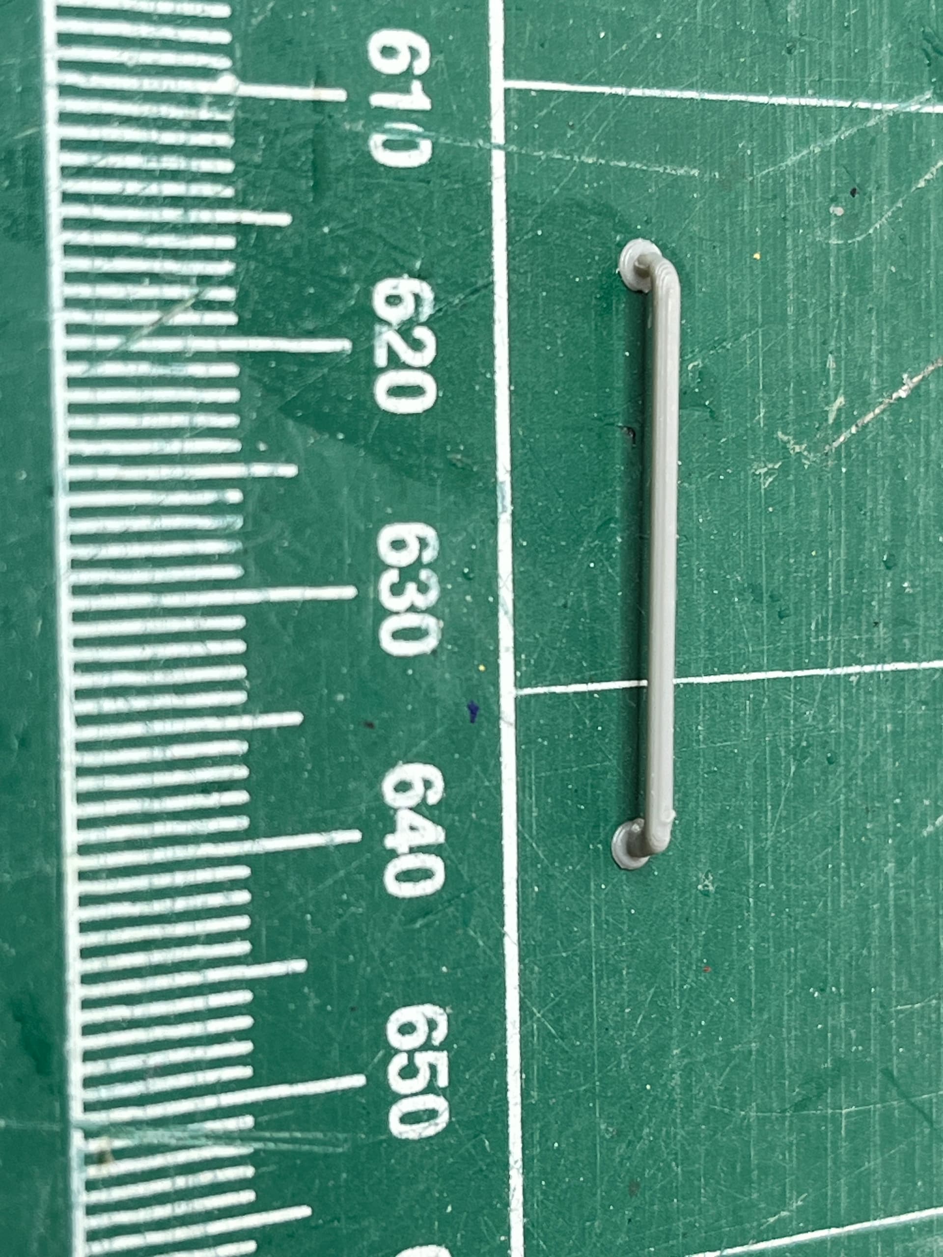
Thoughts on part creation. For round objects such as pipes most people seem to split them in two so both sides look good. The problem with this is it can be tedious to glue the two halves together. The two halves must line up exactly and still there is an obvious glue seam. For the Saturn V LUT I chose to print the large cross braces as two halves due to a notch at the top and a tab at the bottom. To erase the glue seam I used an old woodworker’s trick, the cabinet scrapper. If you try and sand plastic you get an obvious discoloration due to the scratches in the plastic. If you turn an exact-o knife at 90 degrees and scrape the seam the plastic will come off a little at a time without any discoloration. This works great for larger parts but not for long thin pipes. For these I chose to print them as whole pipes. For the larger pipes use supports. After the supports are removed, that side should be scrapped for the best result. Also print them so that the scrapped side is either down or towards the inside so the best side (the top when printing) is the most visible. For the really small pipes such as the sprinkler pipes which are 1.0mm in diameter, the slicer will not add supports. Adding rafts means you have quite a bit of cleanup on the underside. Since these pipes are so small I chose to square off the inside, the side that is glued to the launcher sides. With the square side down you will get better adhesion to the print plate. This is an artifact that you won’t even notice. Here is cross section of one of the pipes.
Another trick I have used sometimes, especially on the side panels is to create parts that do not require supports. In this case the side panelss have I-beams and if these were printed as true I-beams they would need support and the supports would attach to the printed panel and cause unsightly artifacts. An alternative would be to print the outer flanges separately and glue them on. This was the way the Saturn V LUT floor structure is created. For the side panels I chose an alternative, to angle the inside corners so no support is required. This is not visible and falls into the shadow. If you look close you are not sure if you are looking at a shadow line or a not square inside corner. Here is a cross section to visualize what I am talking about and a picture of the resulting panel.

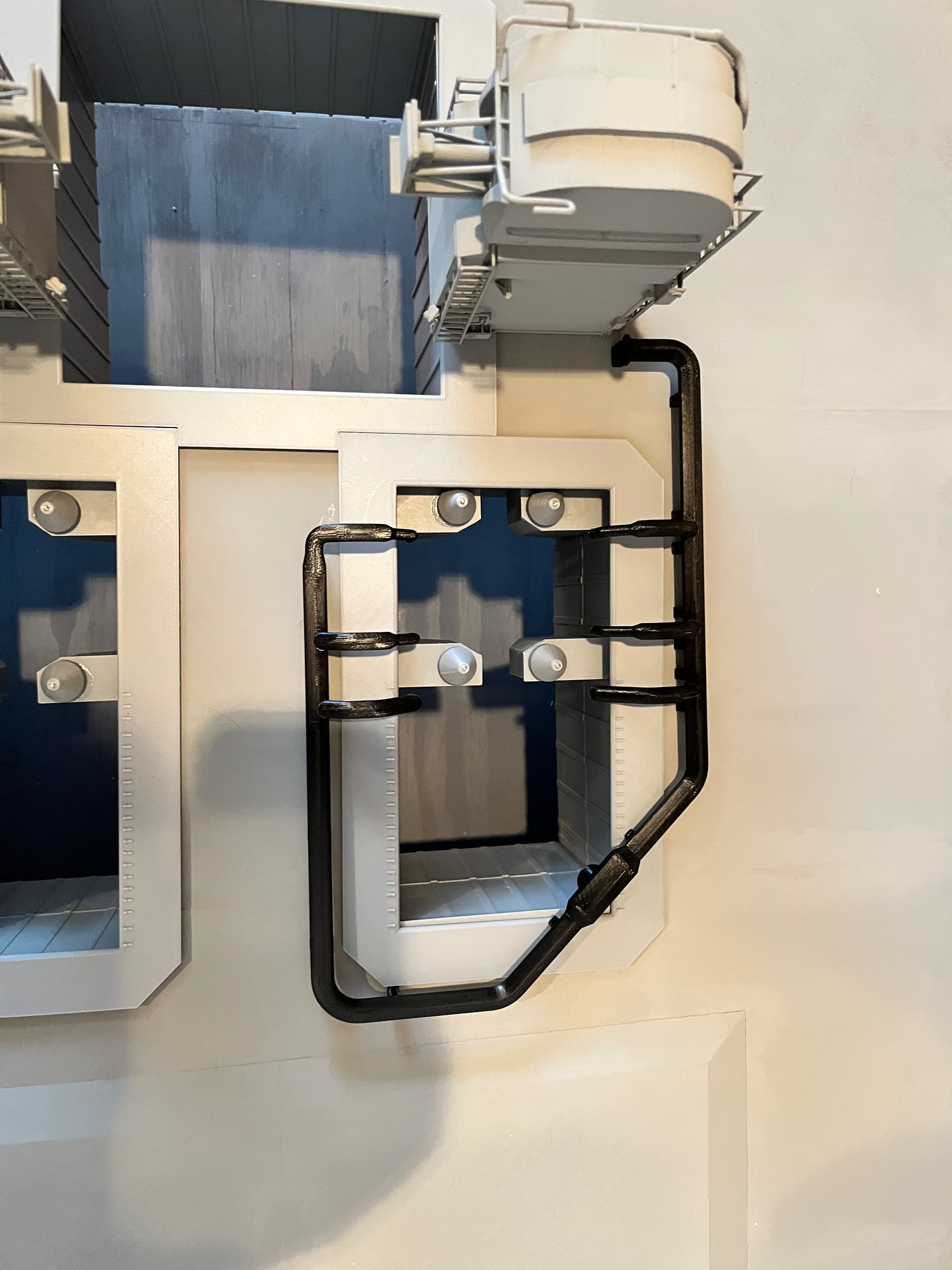
The LH2 piping is compete, all but the hangers which glue to the underside of the blast shield. In the first picture you can see a bypass valve from the supply line to the vent line. I have also added the sprinkler pipe and a square cable shield for a future camera on the top deck. The railings are also going on.
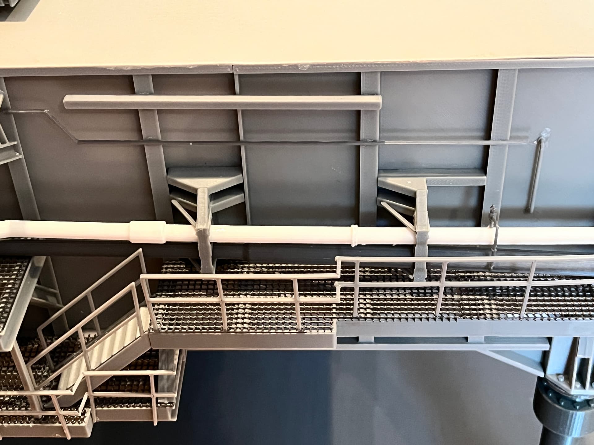
Here is the valve complex. The supply pipe is white and just behind it is a grey vent line, both going to the LH2 tunnel. Above those is a small sprinkler pipe.
1 Like
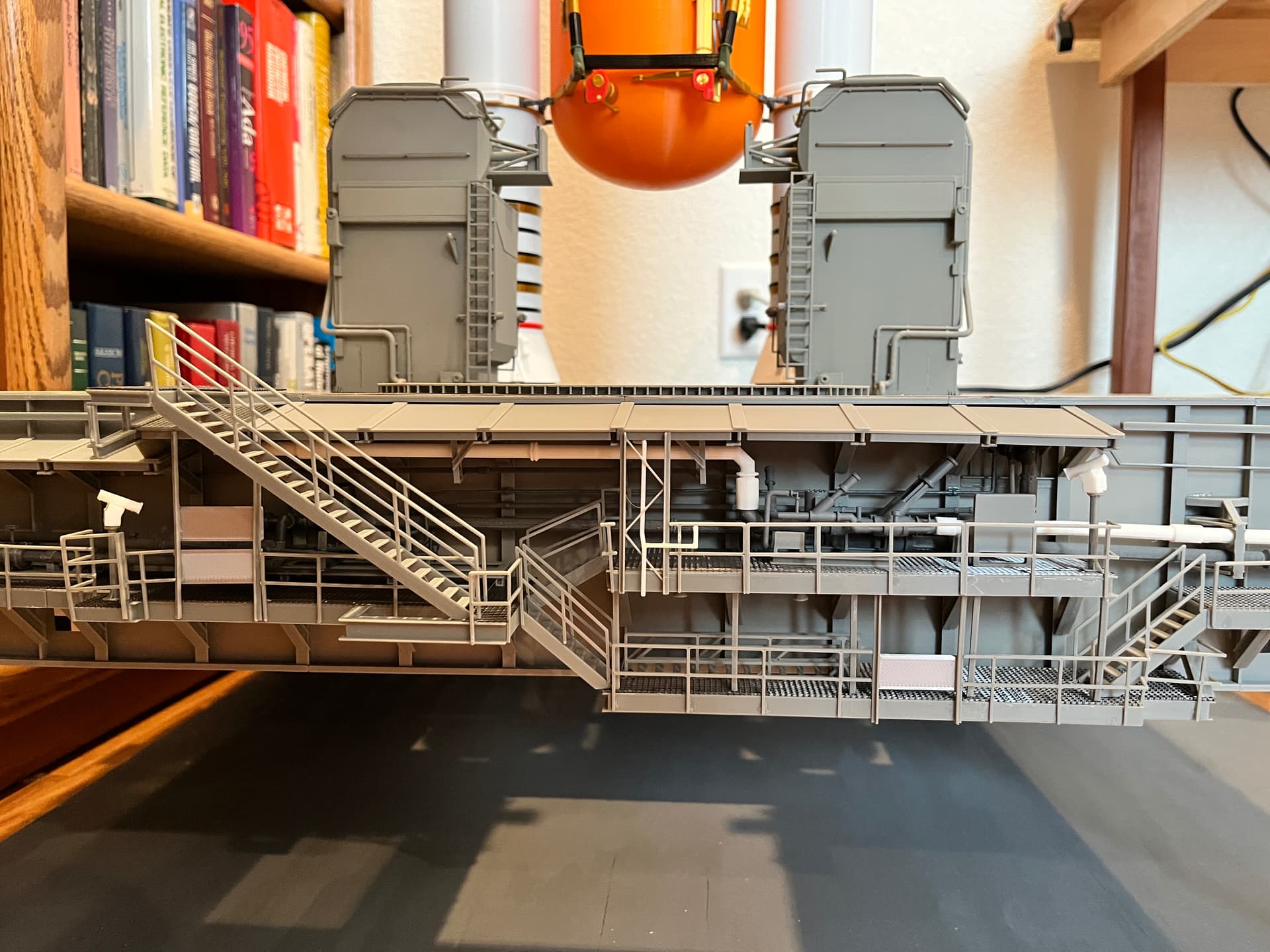
Side 1 is now complete. This includes lots of equipment and the railing, lights and cameras. The parts have been published. Now I am going to work on the equipment on top, starting with the deluge pipes.

2 Likes
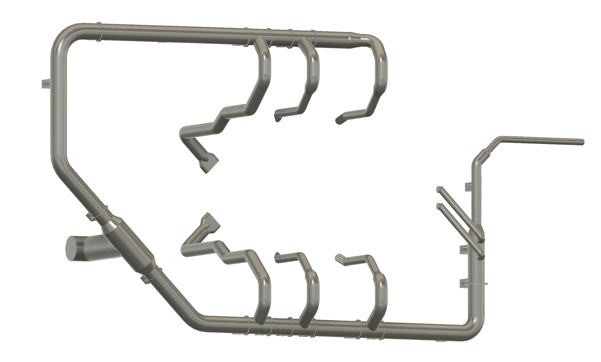
Working on the deluge pipes. The pipes around the SRB engine chambers are mirror images of each other. The pipe design is almost complete. It is a real rats nest of pipes, way too large to print as one piece and it would be impossible to install it as one piece. The reason it is black is because for test prints I use either black or white filaments which is much cheaper than the colored variety. The first slice of the part is horizontally at the top of the deck, level 0. There are 14 pipes that hang down into the engine chamber. Of those 14 pipes, there are 4 unique parts so this makes sense. The remaining part is still way too large to print as is so I divided it into three parts. Two of the parts are shown. There is a third part that wraps around the TSM to spray water into the ORB chamber. There were some minor tweaks done to the parts before adding additional details. Just about ready for a final print.