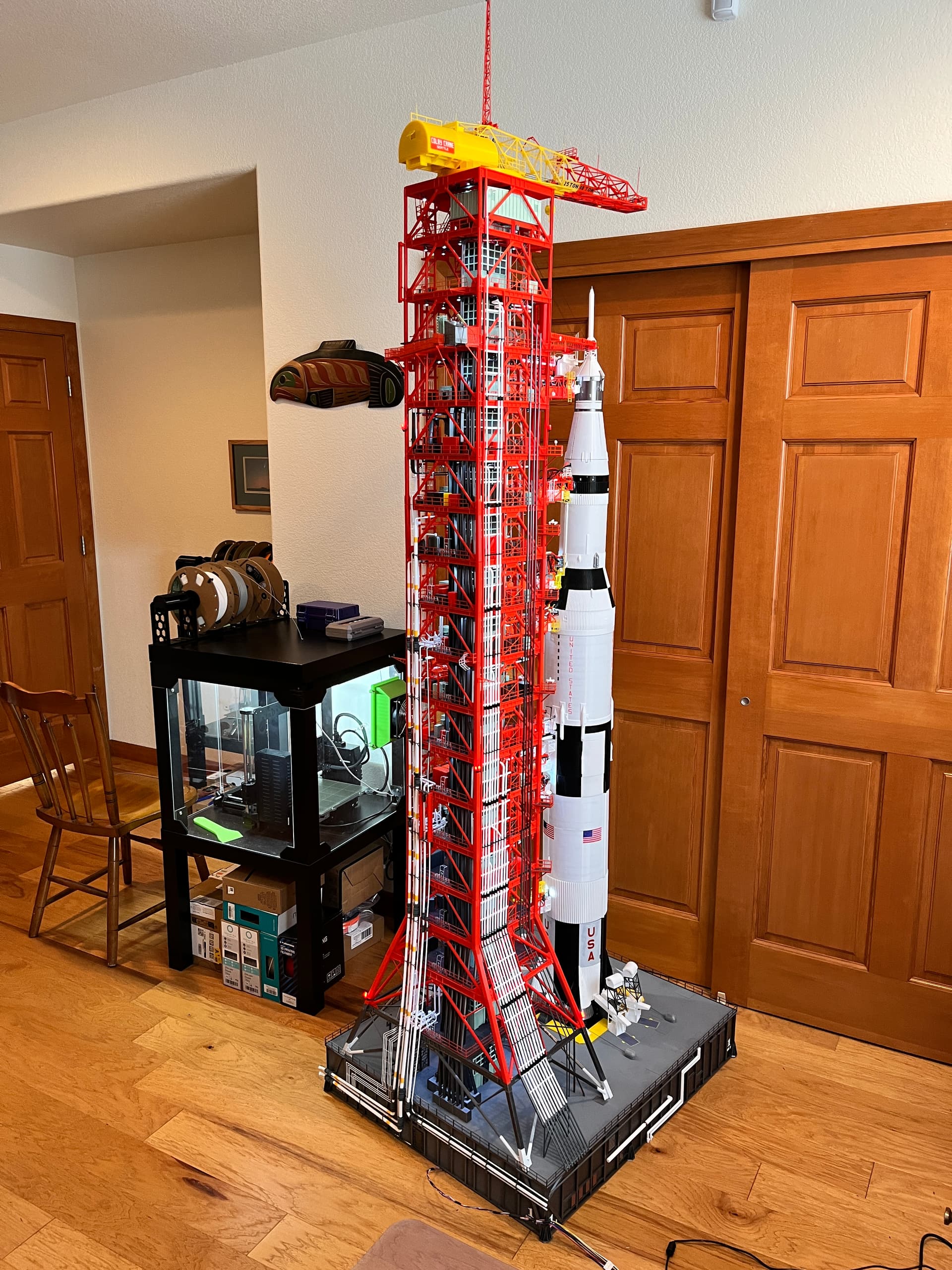
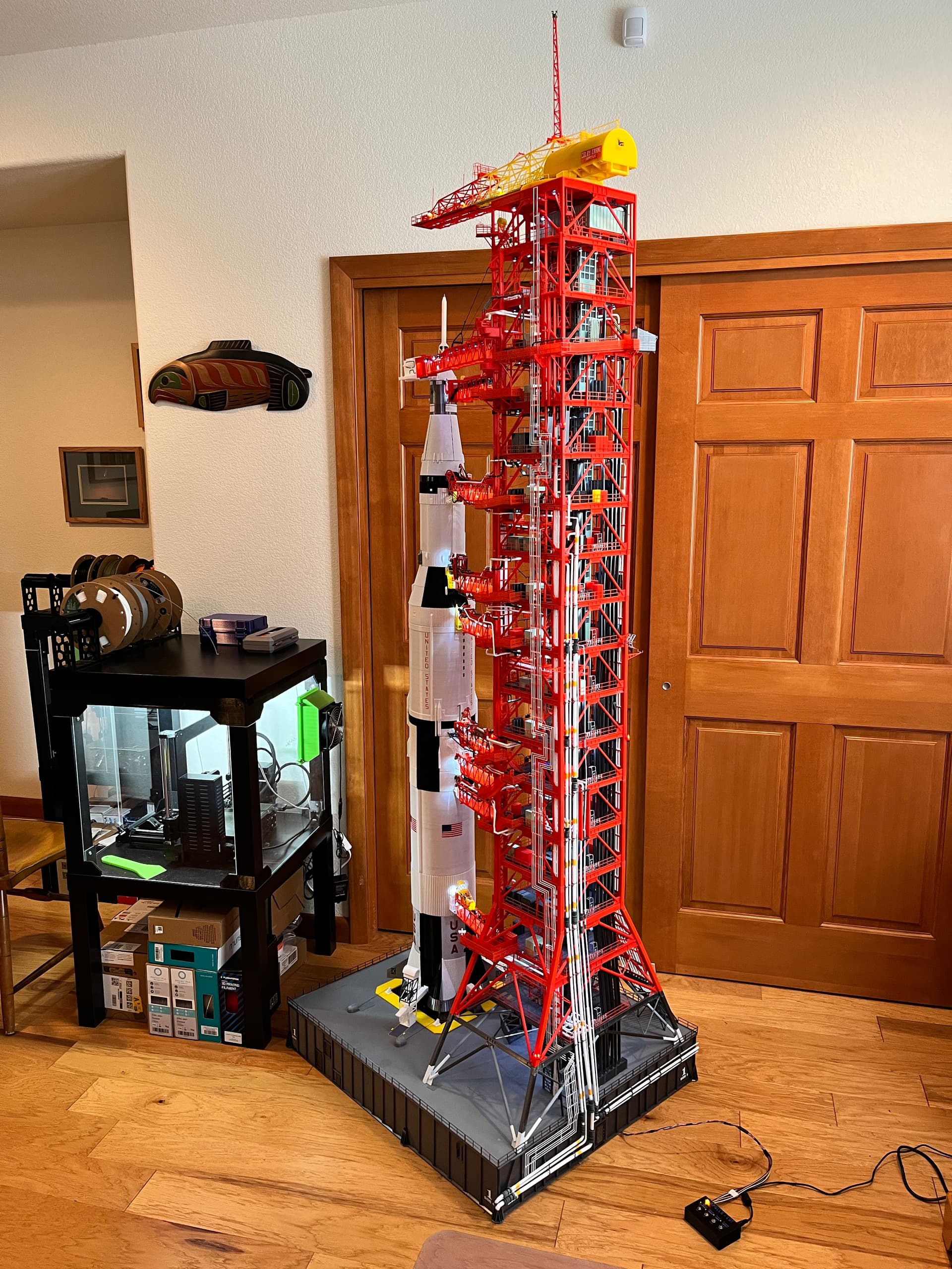
This is a completed model I documented out on an obscure build site. It is hard to get to so I will move some of the info over to this site. This is a 3D printed model. The great thing about 3D printing is you can make your own parts any size you want. I use an FDM printer for the large parts and a resin printer for the fine detail. The model parts and instructions are out at bglasford1 | Printables.com This model is large, over 7’ tall with a total of 5614 parts so it is not for the faint of heart but well worth it. I tried to use as many parts from other people as I could find. The Saturn V rocket is from the Amphioxus available on Cura for a reasonable price. I owe a great thanks for all the contributors at LUTGroup@groups.io | Home. From this site I was able to download all the original NASA documents used by the people that constructed the LUT. Without this information this model would not have been possible.

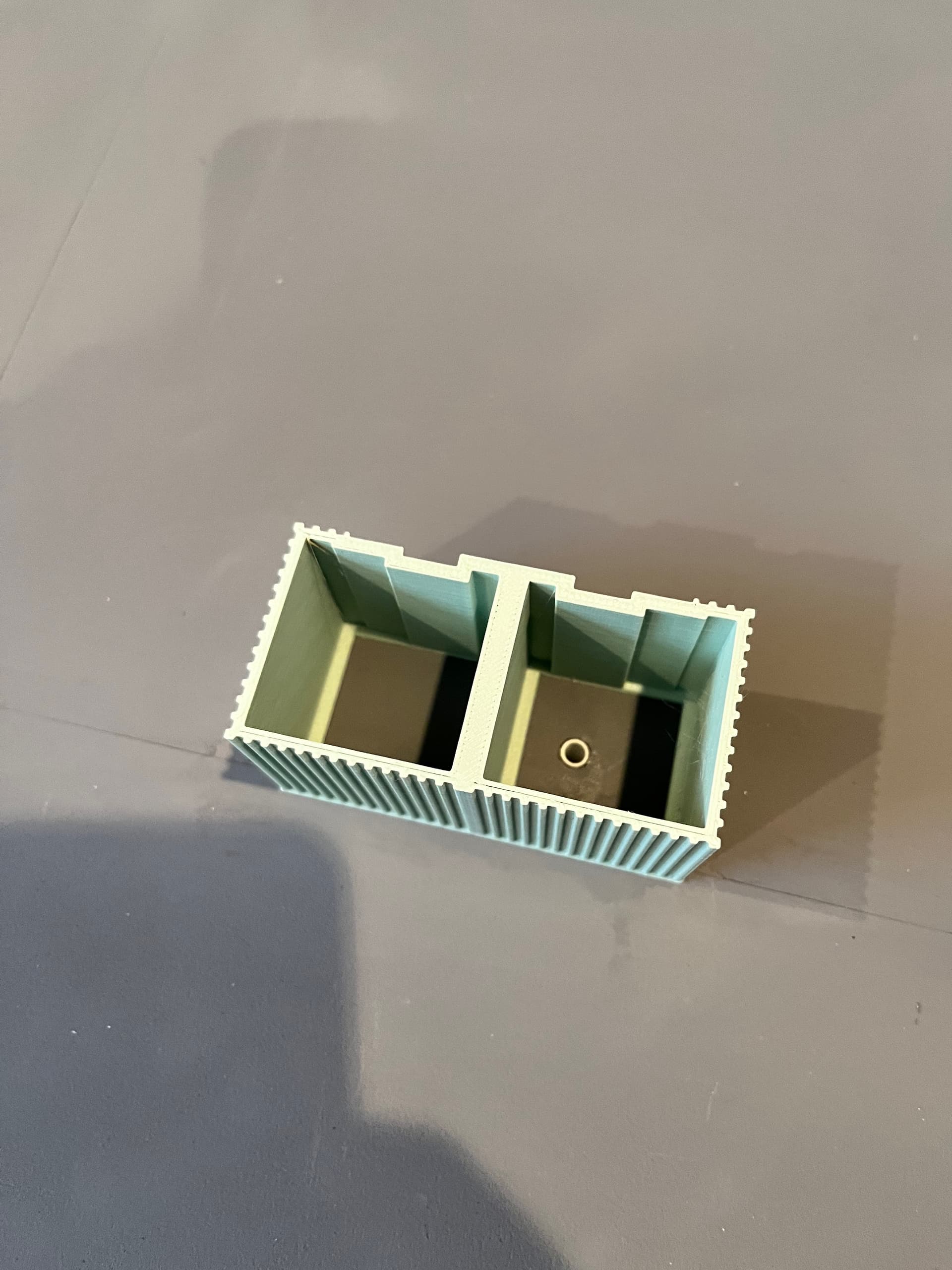
I started by building the Saturn V. It is well documented by the developer so I won’t go into that build. I also created a crawler to lift the entire structure but given the height of this model I will put the crawler under the shuttle launcher that I am currently working on. Once you print and build the Saturn V, the next thing to build is the launcher portion of the Launcher/Umbilical Tower. The launcher is printed skins that are glued to a wooden box. This model is heavy so you should make the launcher box as light as possible. I used 1/4" plywood and interior cross bracing. I don’t have a picture of the interior of this launcher box but here is an interior picture of the shuttle launcher box.
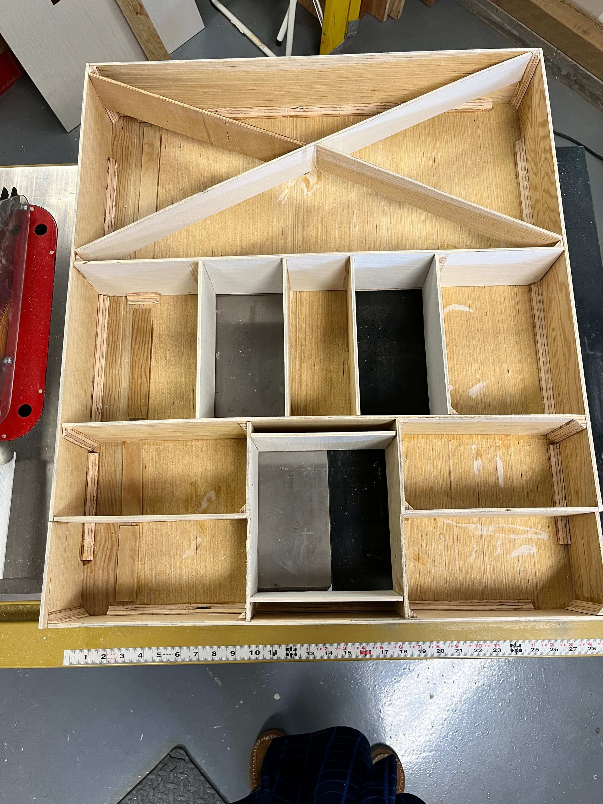
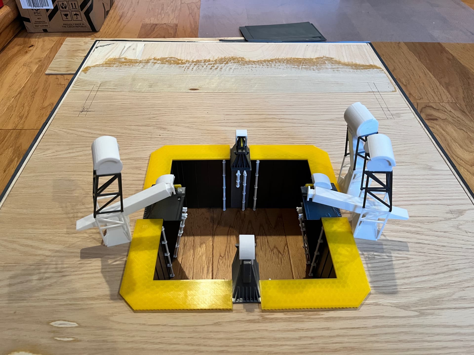
Here is an example of the information available from the LUT Group. This is a page showing the dimensions of the launcher. It is important to get the overall box size, location and size of the engine chamber, and the location of the four tower legs. Getting this as accurate as possible will pay off later. It is not critical to make the wood box look good since it will be completely covered, except for the bottom. Here is a picture of the completed box where I am starting to lay out some of the engine chamber parts. You can see where I did some sanding on top to get it absolutely flat.
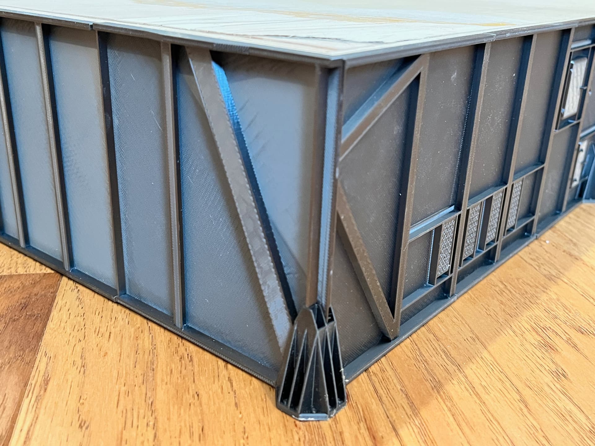
Here are some of the side details. The sides print flat. They are not true I-beams. To make it easy to print I did a trick where you don’t need supports when printing. The corners are where the launcher is placed onto legs that will not be used for this model but will be used on the shuttle launcher.
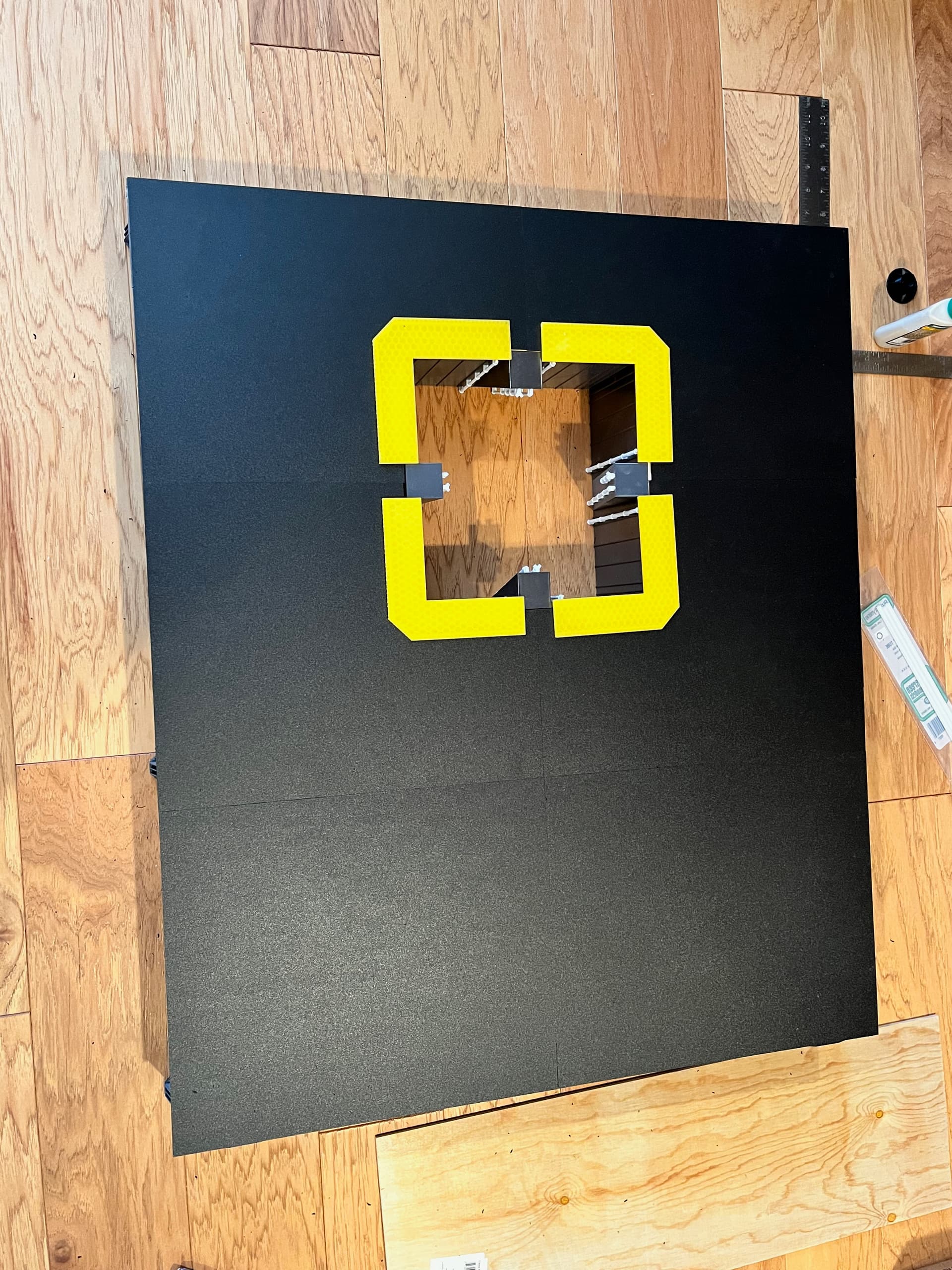
3D printing has come a long ways in the last three years. The printer I used for this model would print a satisfactory flat panel for the top so I used plastic sheeting I purchased. I currently use the Prusa MK4S printer which makes great flat sheeting. This model was printed on the earlier MK3S printer. Here are some of the flat sheets being test fit.
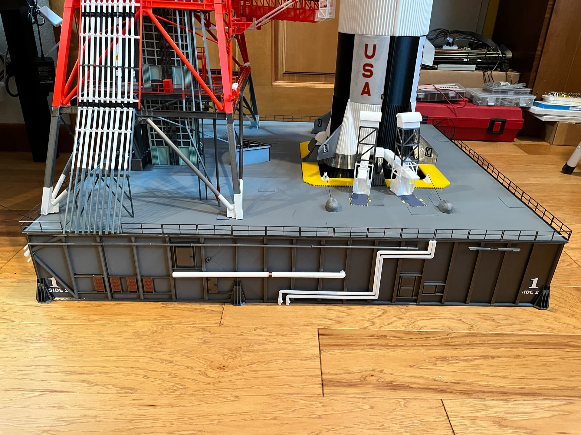
Here is a picture of the completed launcher, side 2, with the completed railing in place. I added the railing as the last step. Notice that I provide decals you can print with self adhesive paper. Getting to know how the sides are numbered are important as everything is named based on the side number.
One last thing to note about the launcher. The model is lit with small LED lights using the same number of original lights in the correct locations. The crane on top is also functional, using two stepper motors. The wires for all this run up through the elevator shaft so you need to add a pipe through the launcher where the elevator will be located. You can see in this picture the first section of elevator is placed and a hole is drilled through the box with a styrene tube glued in place.
OK, enough about the launcher. Now onto the fun part, the umbilical tower. It is best to build it up from the bottom one floor at a time. This model is so tall and heavy I chose to segment it into removable parts. The launcher is definitely the largest, heaviest part. The Saturn V is already segmented so the only question is where to split the tower? The tower levels are labeled based on the height about the top level of the launcher (level 0). The crane sits on level 380 or 380’ above the launcher top. I had to work around the swing arm and ended up with seven manageable sections.
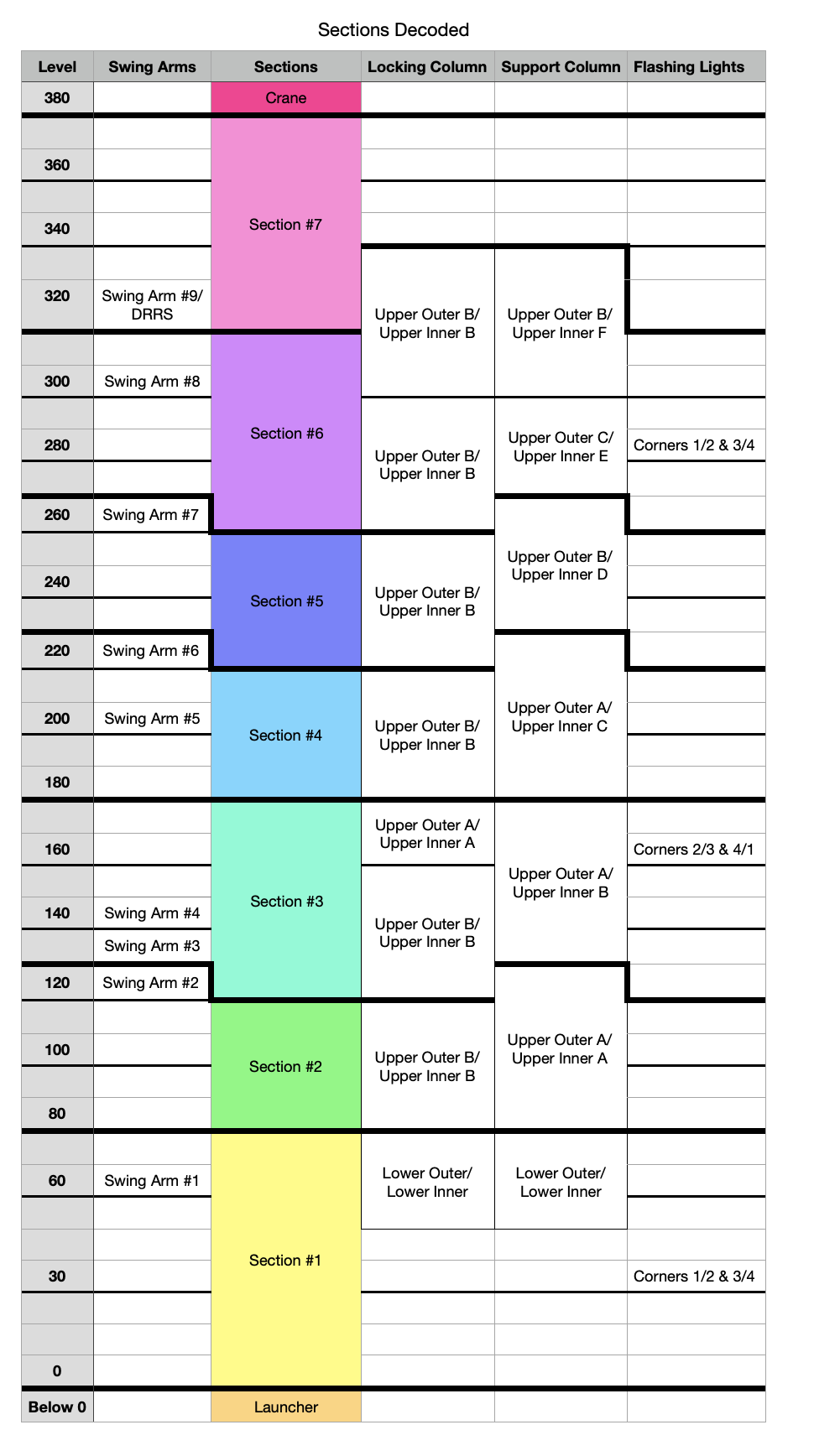
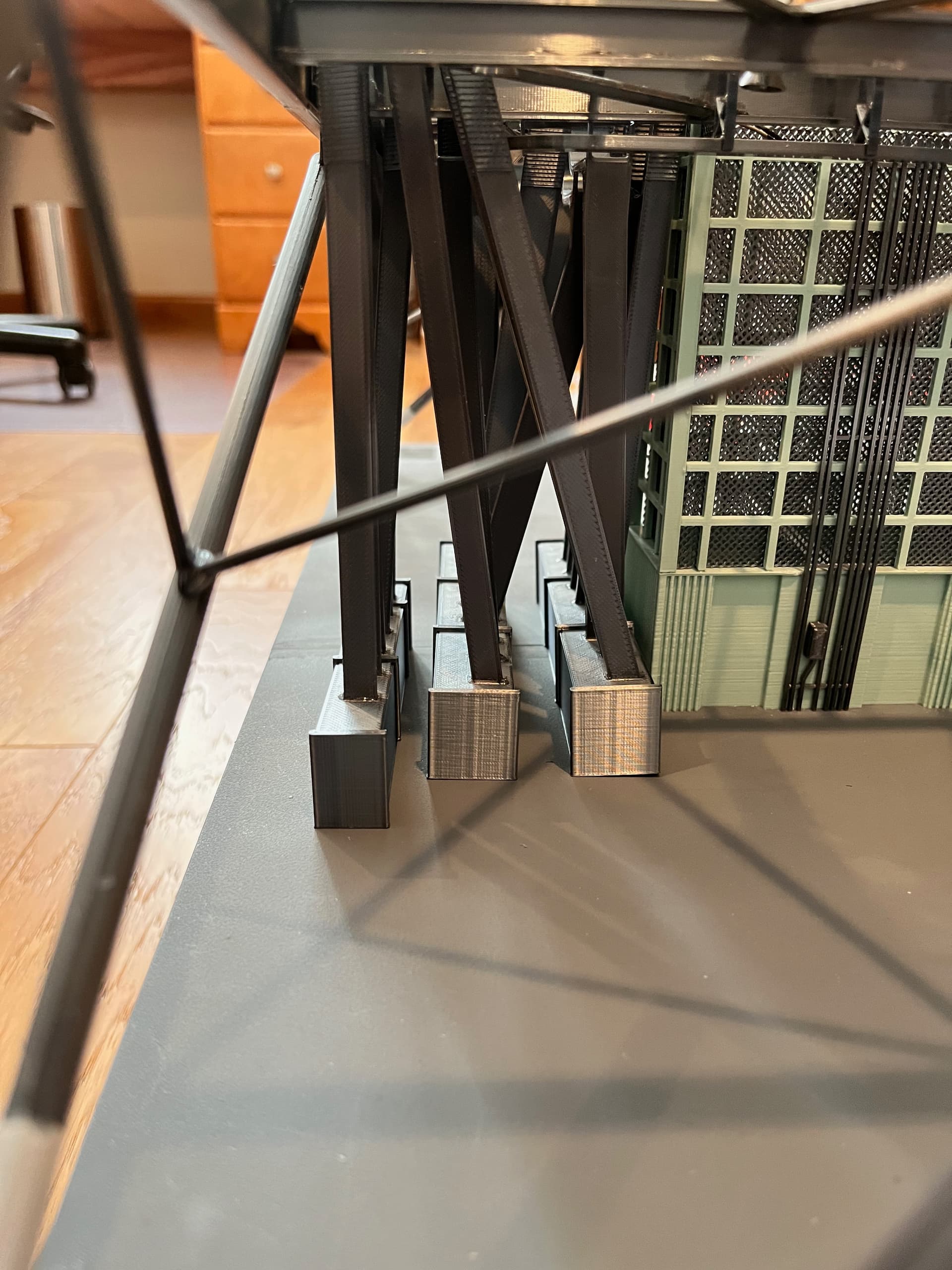
The general steps are start with the structure of the first section. Glue each level and its legs together but keep the levels removable for now. Then add the elevator, stairs and equipment, the interior stuff. Once satisfied, glue these levels together into a single section. Now you can add the outer pipes, railings and such. Finally add any swing arms to the section. The first section’s structure is the hardest because it is angled. Make sure everything is true. Notice that for the first level (level 30) the side 3 legs are positioned such that they visually extend through the side of the launcher.
The floors interlock so I found it best to build the structure floors for the next section but don’t glue the floors to each other until as late as possible in the build. Stack the floors for the next level so they align. For the first section it is best to build it upside down, making sure the angled legs align.
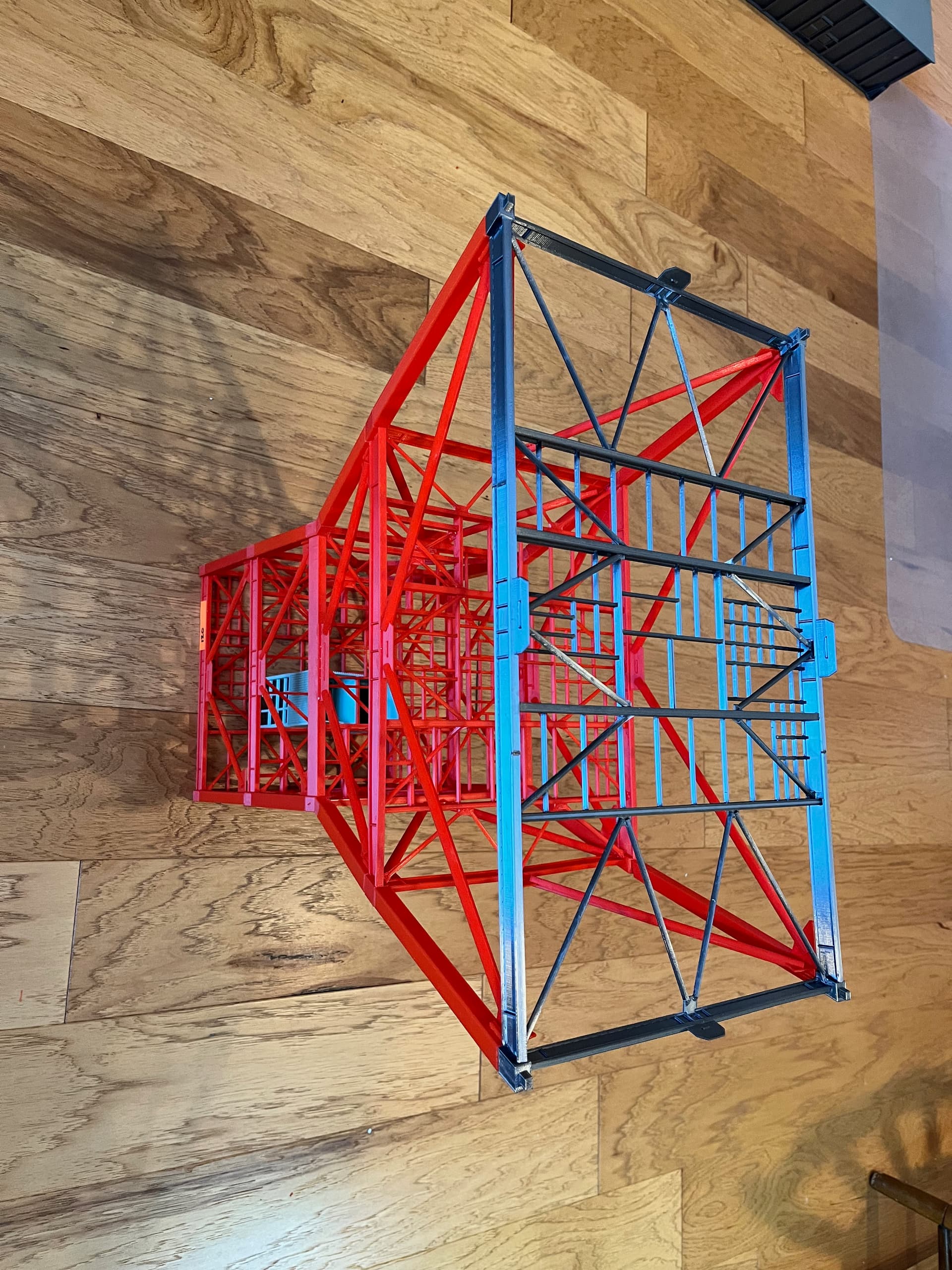
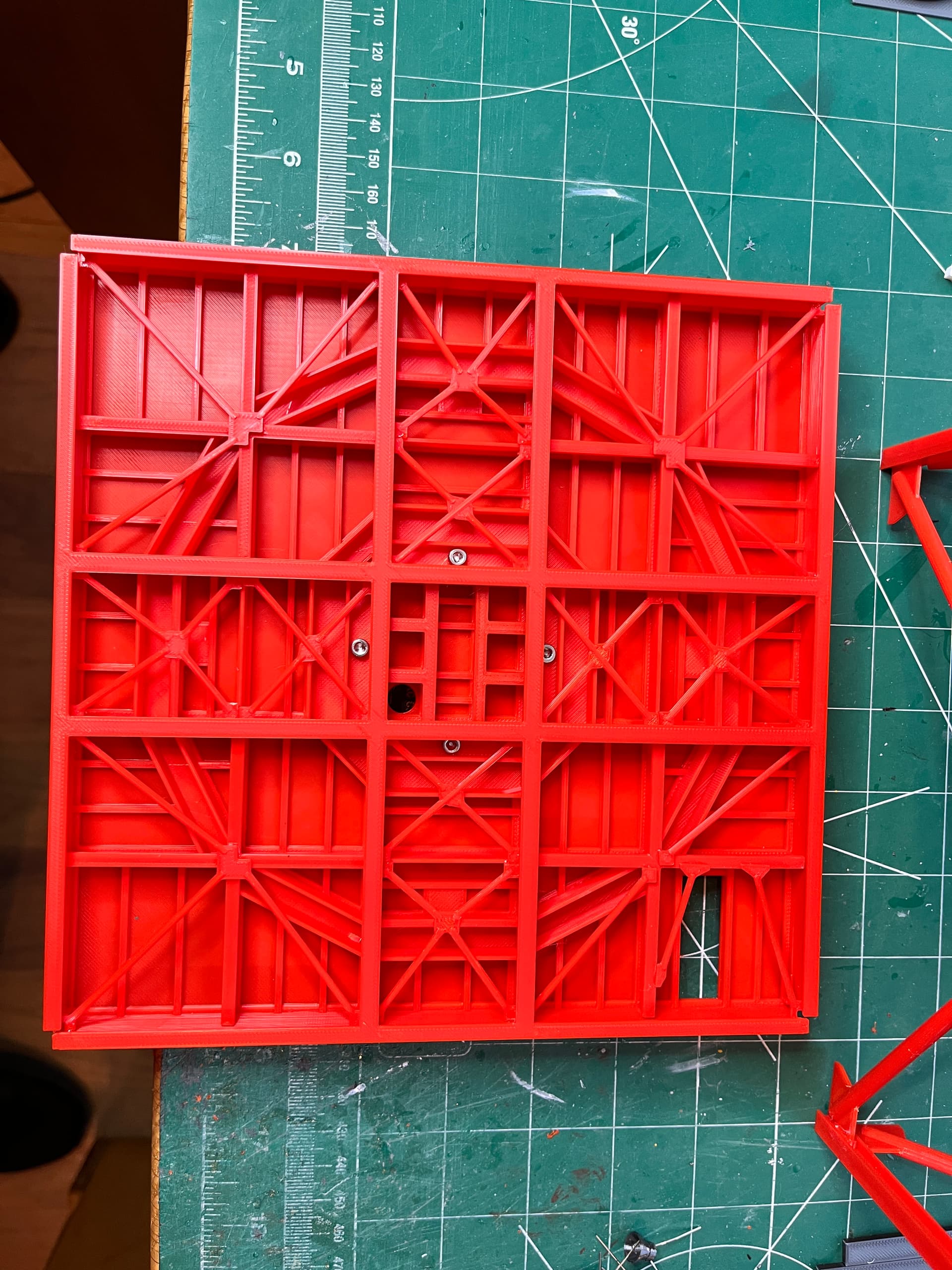
Critical to the overall look is that the vertical corner beams and the horizontal outer beams get smaller as you go up the tower. The corner beams even go from box beams to I-beams. Here is a picture of the Level 340 floor versus the Level 60 floor.
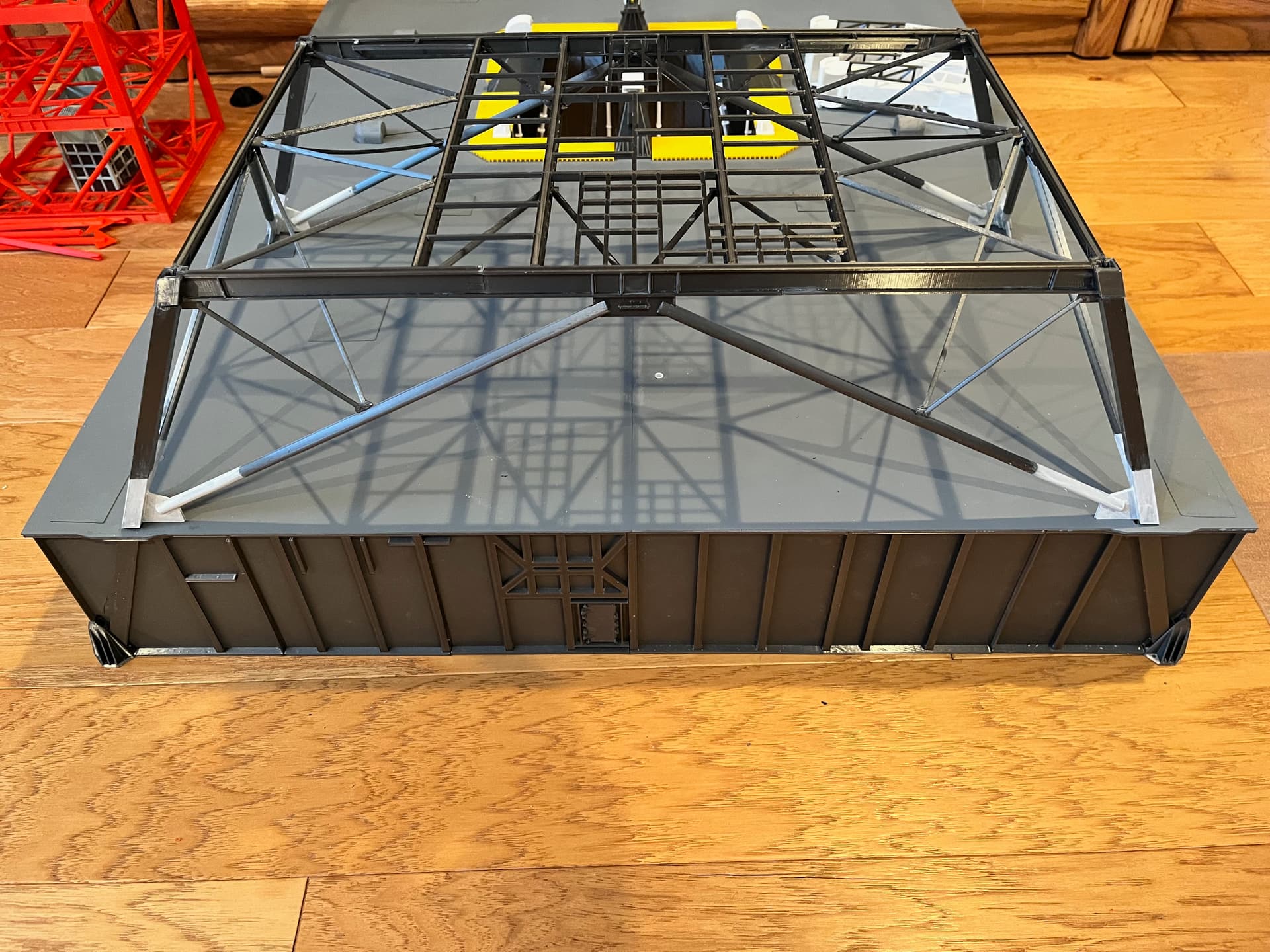
This site is severely limiting how many posts I can do in a day so I will just hit the highlights. The last structure picture I will show is the underside of the top floor, level 380. Most of the floors are 40’ x 40’ which at scale just fits on a standard size 3D printer. The top surface is flat so it prints upside down. On the underside the various I-beams are different size and therefore different heights. To make them true I-beams the underside flanges are glued on as is the various cross beams. This floor’s design was by far the most complex part to create. This structure has only 21 parts so it takes a while to print but is relatively easy to glue up and surprisingly strong.
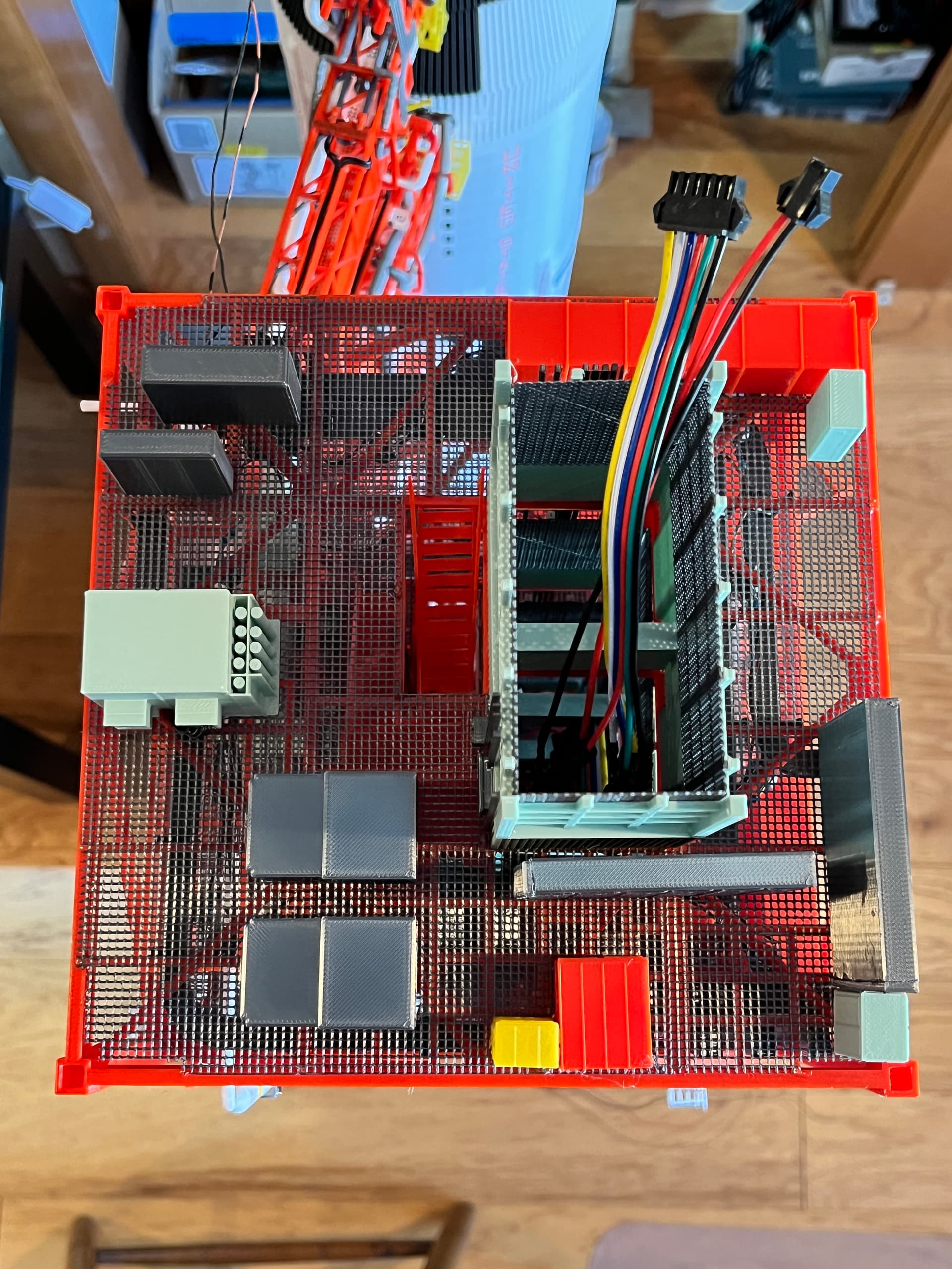
When adding the equipment for each floor I glue the equipment onto the top of the floor including the elevator shaft. Most of the equipment was created by Aviator67, a great set of parts that have great detail. You can see the wires going up through the elevator shaft and the connectors used to separate the sections.
On the underside of each floor hangs the stairs, cable trays, piping and lights. It is easiest to turn the structure upside down and add all these parts on before turning it right side up and gluing onto the stack. I was unable to get every light in the exact position per the NASA drawings but it was close.
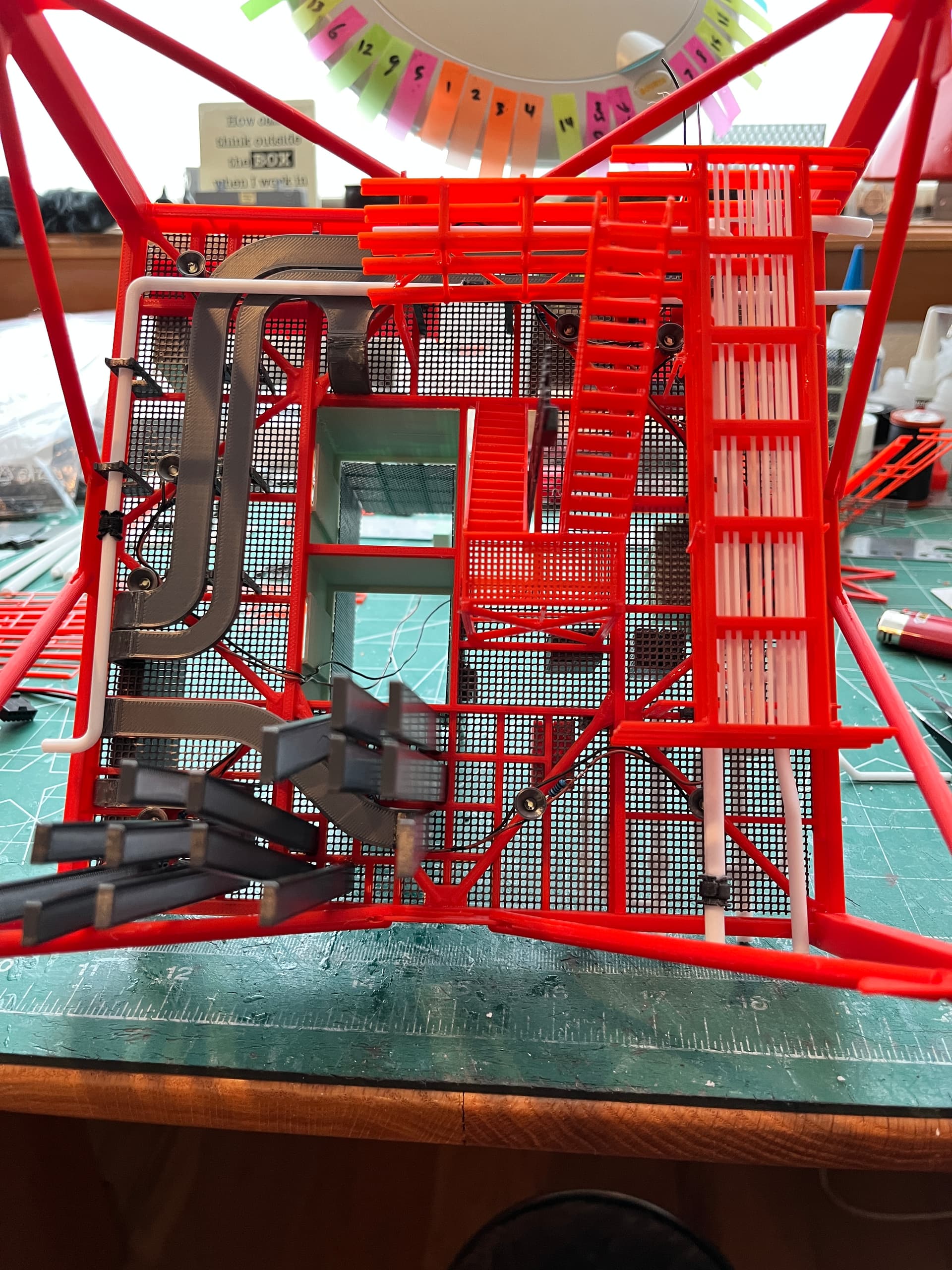
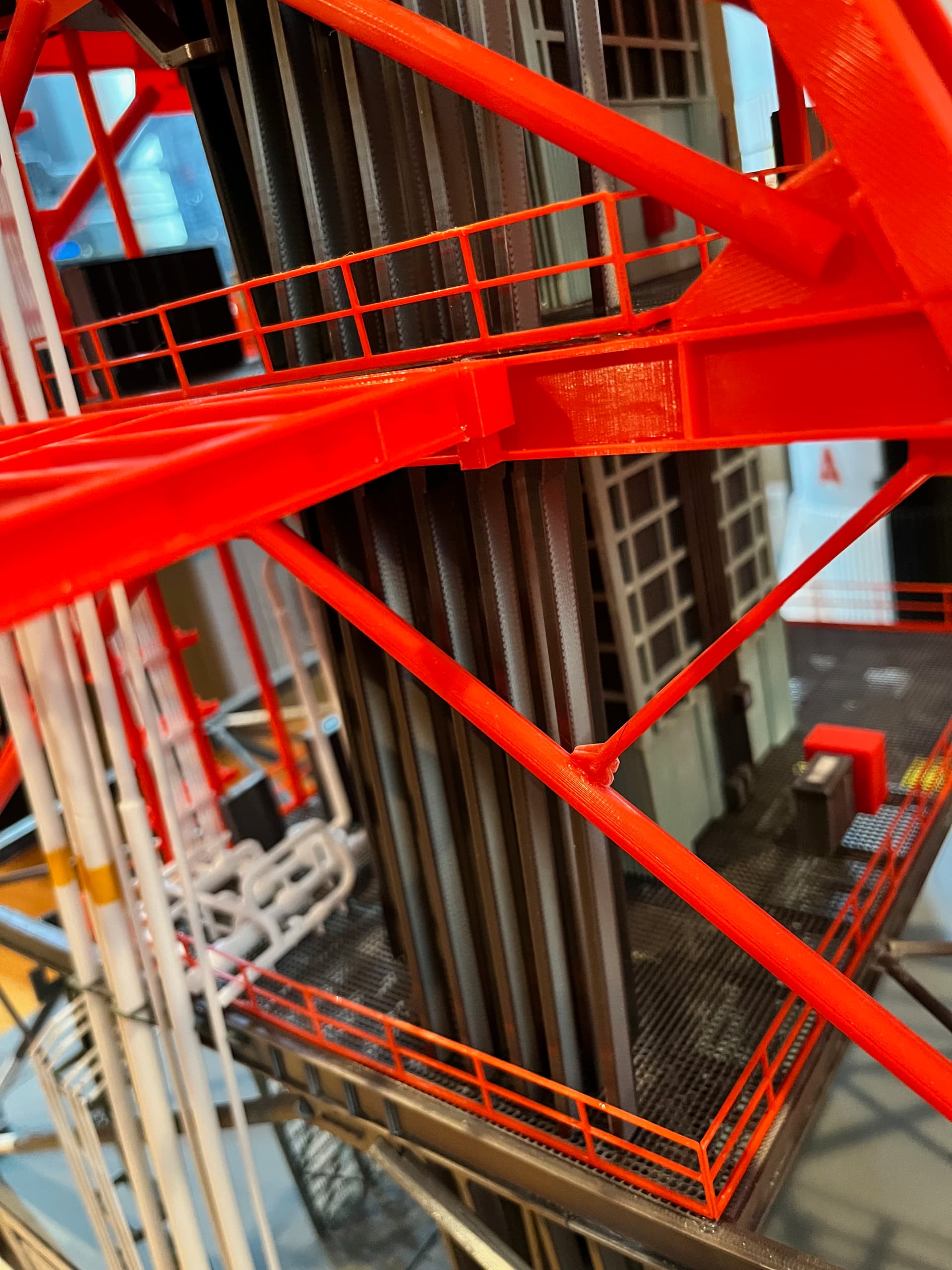
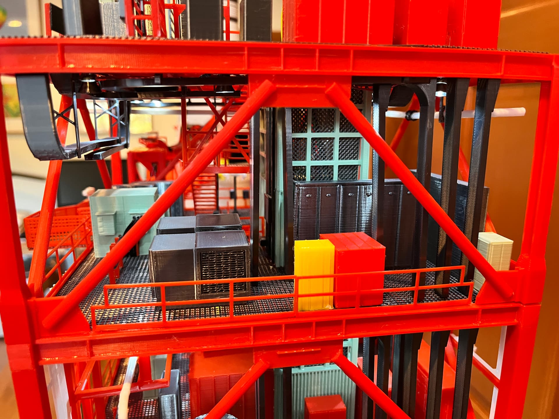
Here is what level 260 to 280 looks like without all the exterior pipes added. There are three ways different people used to refer to a level. To make it as straightforward as possible I chose to refer to a level as “lower floor to upper floor”. Example: the first level is level 0-30. If you consider building this monster of a model, I would highly suggest adding lighting. The lights really bring out the interior detail even in the daytime.
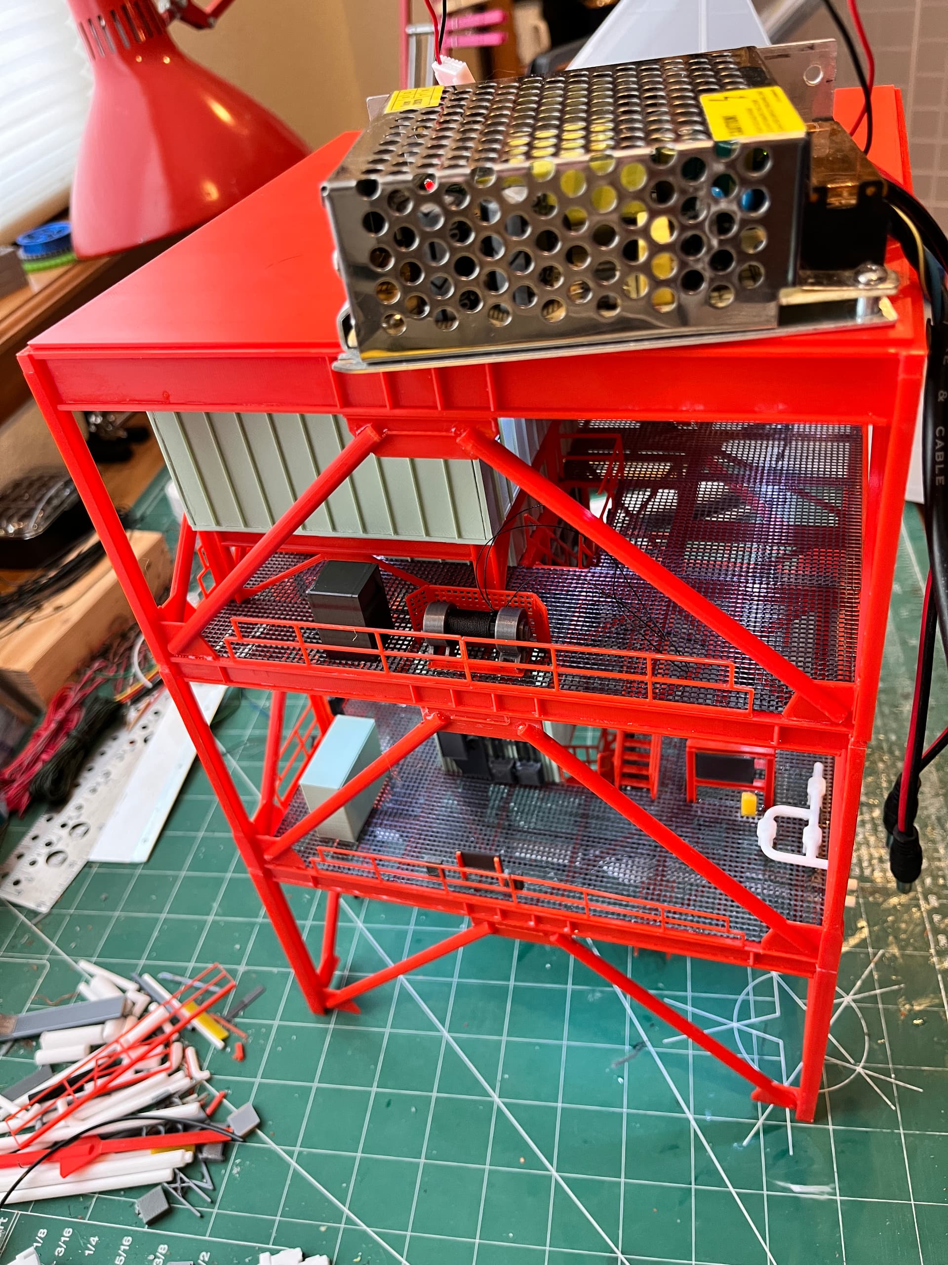
At leve 360, just below the crane is the machine room that contains the hoists and equipment that make the elevator work. This presented a problem since the wires could not from here go up the last level to the crane. To solve this I chose to hollow out one of the cross braces. There is one control box at the bottom. This box needs to control lights on the crane, flashing warning lights, crane rotation and the winch. This would have been too many individual wires so I chose a four wire solution that connects two Arduino Nanos; positive, negative and a two wire protocol. In this picture you can see a winch that I wound with thread. This winch raises/lowers the DRRS which is a triangular arm that attaches the top of the rocket to the tower. You can see that I am testing the lighting of the final section before more equipment gets glued on.
The cable trays are somewhat complicated. I created a spreadsheet to sort them out. Each vertical cable tray has a designation. The various slots they go through have another designation because cable trays can move from one slot to another as they go up the tower. The cable trays were placed behind the elevator shaft to keep them as far away from the rocket flames as possible. The cable trays on the first three levels are complicated. It gets easier from there on up.
Amazing… Truly amazing work.