I have begun work on the Revell Republic Star Destroyer (Star Wars), which has sat in my stash for a long time with the idea that when I got around to it, I’d definitely want to light this thing up.
I bought a lighting kit intended for this Star Destroyer from a place called MadMan Lighting. I have very little experience lighting models, having done an Iron Man kit about a decade ago from a collection of LEDs, resistors, and wires; this is my first time working with a pre-made lighting kit such as this one.
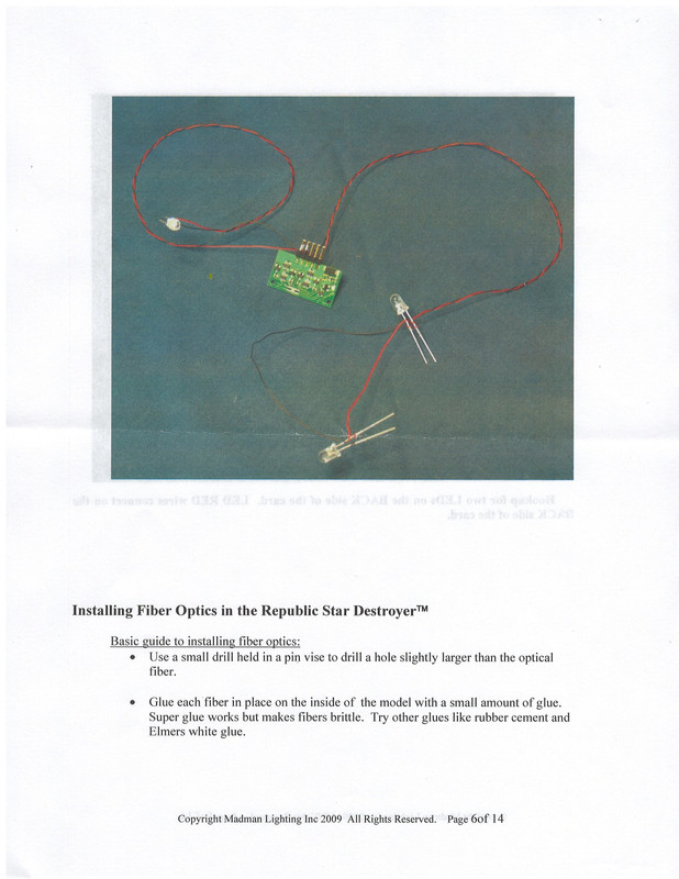
It features a small electrical board to which the wires attach from a “mini-connector” that itself is wired to the power supply, in my case 12v from 8AA batteries. I’ve done the wiring between board and power supply as per the kit’s instructions, which state that I should see the small LED light built into the board light up. Not happening. I reversed the wiring connections, and still, nothing.
Batteries are brand new. My concern is that I might have a bad board, but given my lack of understanding of how it works, that may not be the case. Has anyone built this kit with this lighting kit, or one of his other kits, that might have some suggestion as to how I should proceed? Or could I just ditch the board and wire this thing up with resistors (I’m assuming the board performs the function that the resistors perform, although not being an electrician or electrical engineer, I readily admit that I’m a complete novice in this arena).
Chances are that you’re not getting power to the board. Most battery boxes that I have seen recently have all been really poorly made, so sometimes they require a little work on getting proper contact between the batteries and the contact leaves and springs. Aside from that, I know you probably already checked, but make sure all of your batteries are installed with the correct polarity. I’m pretty sure that the board itself is fine. Those tend to be pretty reliable. It has always been the battery boxes of the power supplies that have been problematic.
Check the amperage output of the battery box as well. If the voltage is correct, but the amperage doesn’t match, you"ll have problems getting the board running.
If memory serves, a lot of the Madman boards required either 9 or 12 volts at 2 amps. Madman boards were usually pretty simple affairs.
Madman Lighting was sold off to Tena Controls a few years ago (2018) and I suspect that you may have a Tena designed board released under the Madman label because you’re not required to solder resistors onto the board and you’re using quick connect terminals instead of soldering the wires to the circuit outputs. Double check the amperage requirements carefully, because these boards (particularly those with special effects) tend to require a little more juice. These sorts of boards seem to favor a plug-in transformer to run most efficiently, but the idea is the same - you have to match both voltage and amperage to get things to work.
Edit - also check your connection instructions to see if a wire wrap tool is needed for installation. Some of the Madman stuff required it.
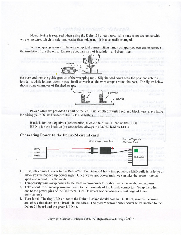
This is one that does require the wire wrap tool. The board has 5 posts, one of which the instructions refer to as the power post. That is connected to the micro-connector (male-female plug essentially), which in turn is connected to the power source.
The instructions leave something to be desired. They are inconsistent, I suppose. One on page, there is diagram showing the red wire to be attached to the “top” post (top side of the board), but every where else, it clearly says to attach the red wire to the “bottom” post, with the black wire on the “top”. I’ve tried both ways with no successful results.
Got everything connected today and checked that the battery pack was generating sufficient power with a volt meter. Then put the volt meter on the power prongs of the circuit board and get sufficient power there. But still, the on-board light on that board never lights up.
Thought that I would get power to a LED if I connected one, so I did that. Nothing.
I’m bummed about this. The lighting kit was not particularly cheap. I can certainly ditch it and just connect a bunch of LEDs with appropriate resistors, do some soldering, all of that, but you know, I got the kit so I wouldn’t have to bother with that stuff. I’ve sent an e-mail to the Madman Lighting people, but honestly, I’m not sure that I really expect much in the way of a response. Hopefully they will surprise me.
Feels like I’m at a stand-still on this build. I’ll likely go ahead and continue drilling all the holes while I wait for a response to my e-mail. And maybe start working on whatever my next project will be.
Sorry to read that you weren’t able to get it working. You mentioned the instructions being inconsistent about how you connect the battery pack to the board, and that you tried both ways. Do you remember how long you left the battery pack connected when you tried the different ways? Its possible that reverse polarity for long enough may have killed the board. Hopefully you’ll get a helpful response from Madman Lighting.
Unfortunately, anything more than about a second can kill it if the polarity is reversed. Those guys definitely need to get their instructions corrected. I’m sure you’re not the first one to have the issue.
I had reached out to them earlier for a clarification on what size of wire wrap tool to use for this project, and they never responded. Honestly, I’m not expecting a response to this more critical issue either. Seems like a good case study on how not to conduct customer relations, but I don’t know, maybe my business school education was wrong?
A wire-wrap tool? Yikes! That definitely doesn’t sound like a very user-friendly kit. If you don’t already know about them, have a look at Falcon 3D Parts some time. Their lighting kits are kinda pricey, but they’re plug and play. I got their Millenium Falcon lighting kit last year when I came into a little extra dough and its pretty impressive. The hardest part about it was downloading the phone app to control the lighting and sound through bluetooth.
That will depend on whether you spent more time in Blocker than Dudley’s [:)]
Just as a WAG, have you checked YouTube for this component? There’s tons of videos out there on near nigh everything.
My first instinct is that hte micro connector is bad–it only takes one pin bent to not align with its proper socket.
Poking about with a circuit tester is not an ideal way to learn how to test circuitry design. Hopefully, that is not in your future.
Especially as it all sounds simple–you either connect all the anodes to a resistor; or you hook all the cathodes to the resistor, and everything else is just switching. Sigh.
If it is, I may have spotted your problem. You had said that you were using 8 AA batteries to provide 12 volts. According to the link above, the lighting kit needs an 18 volt power supply, capable of supplying 100mA of current. 12 AA batteries could definitely do that. The only problem would be the physical size of the battery pack. Have you looked into getting a 120VAC to 18VDC transformer that you can just plug in? That might be the way to go for a more compact solution.
This one could handle the job easily.
Edit: Oops, sorry. Just noticed the power supply in the link I had posted was AC to AC.
Edit: Here’s one that could do the job, with about 650mA of headroom.
Please excuse me saying this, but 89$ for a PCB and a few LEDs is an outrageous price IMO… And a design that needs 12V or even 18V battery power isn’t very smart, neither. A white LED needs 4V, older digital chips need 5V and if you somehow need more voltage you could use a DC/DC converter - but you can also save money making your customer buy a whole family box of AA cells…
Now I’m sure I could make it work if I had it in my hands… Pity I don’t… But maybe you could post a few photos, I would like to help you.
So you are sure the battery pack is giving you the right voltage… Are you sure about the polarity (+/-) now? If those two things are right and that little LED stil won’t light up, it’s probably time for some debugging on the board.
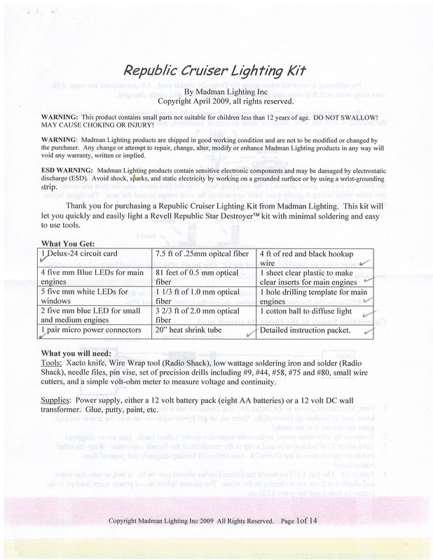
Photographs of the instruction booklet and how I have connected everything.
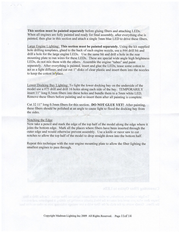
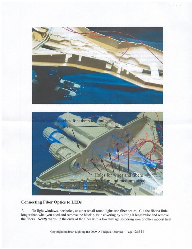
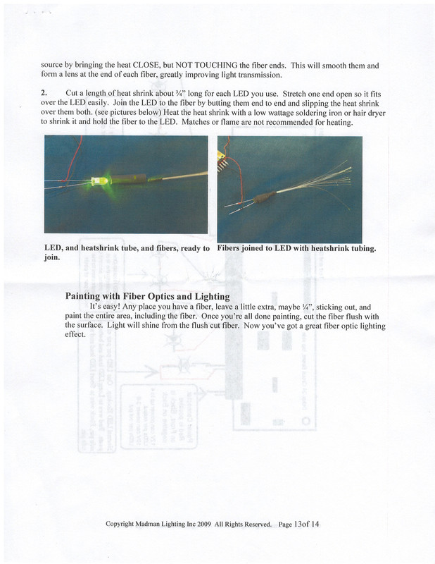
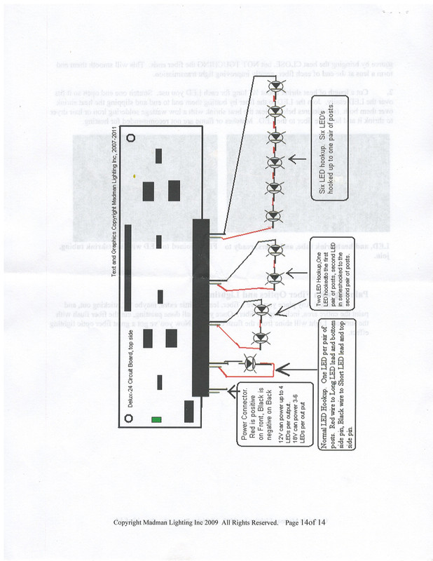
Instructions:
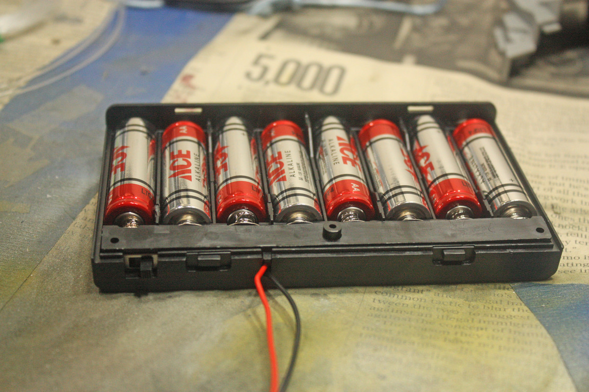
Battery Pack:
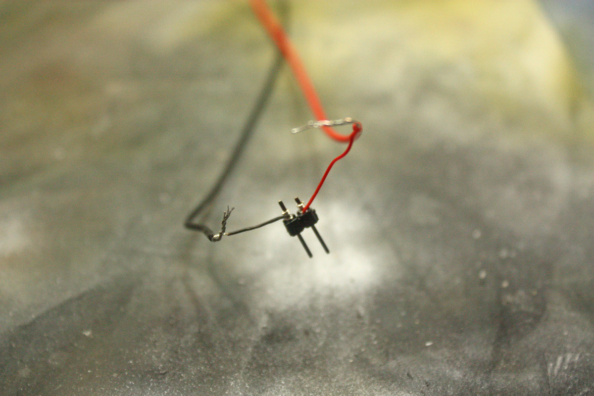
Male end of the Micro-Connector:
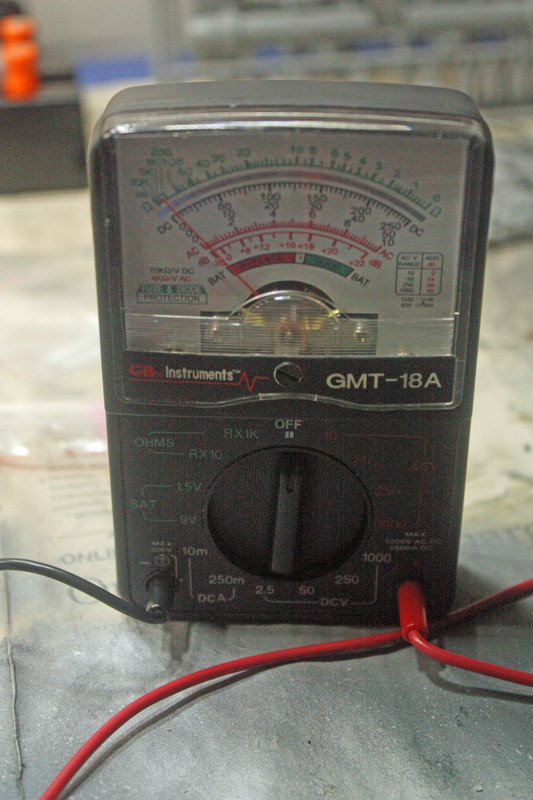
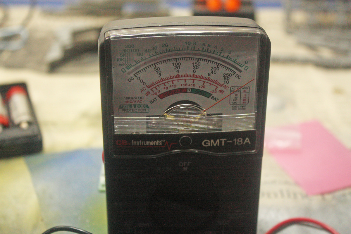
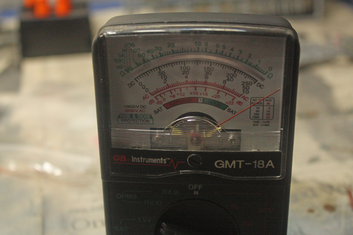
Volt Meter I am using:
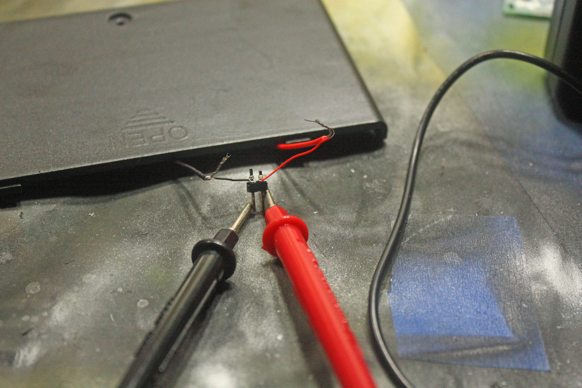
Volt Meter connection to male micro-connector and result:
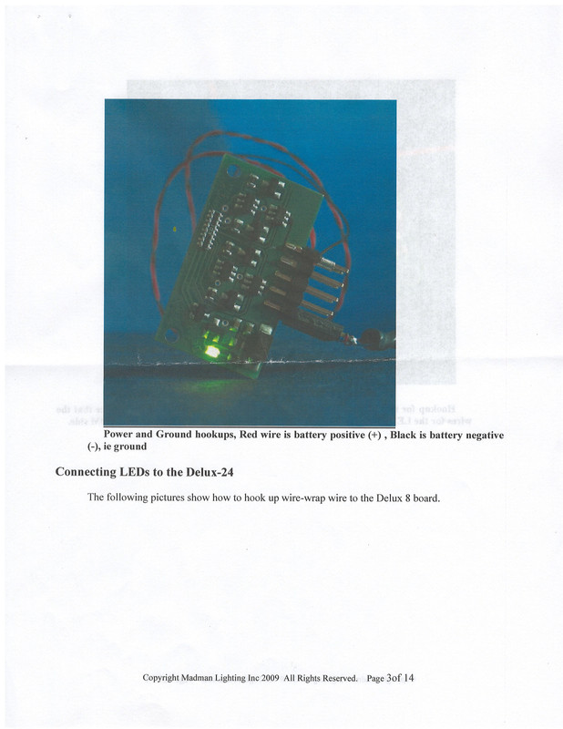
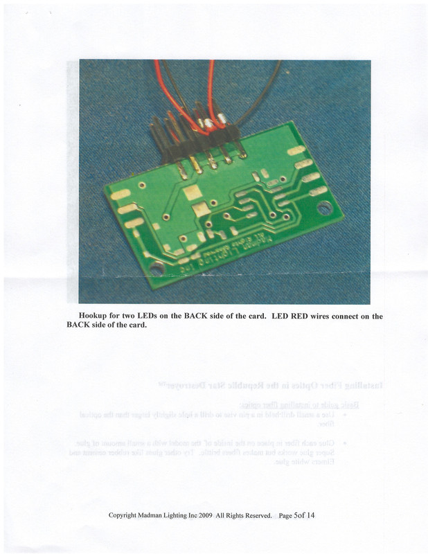
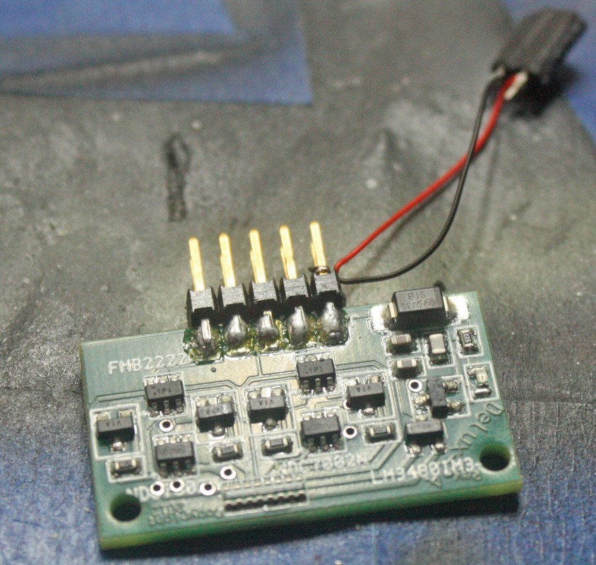
Circuit Board:
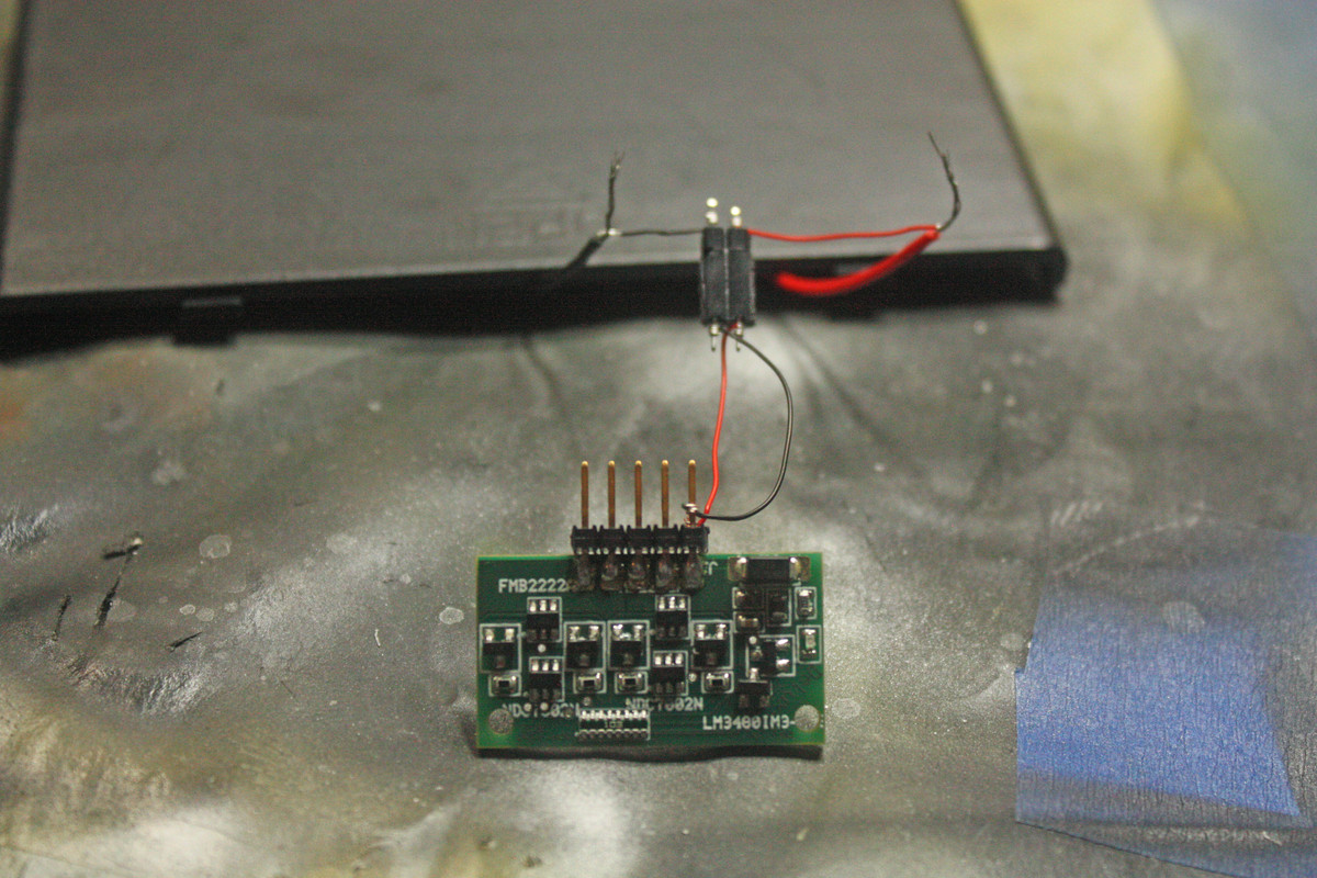
Circuit Board with female end of micro-connector connected to male end:
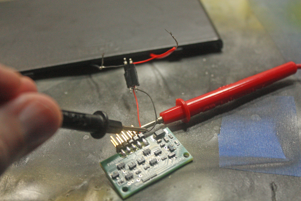
Volt Meter connection to power prongs on circuit board and result:
The unused prongs on the circuit board are intended connection points for the lights, but none show any power on the volt meter. Now I fully admit to being a near-complete novice in this arena, so it is very possible that (a) I have connected something incorrectly and (b) I have no idea what I’m doing. (I say near-complete novice as I did install LEDs into an Iron Man kit I did about a decade ago, but I didn’t take any notes as to what I did then and I also was not using any pre-fab lighting kit).
Thanks to everyone who has responded to me on this issue!
I’ve read the instructions and would like to suggest the following things:
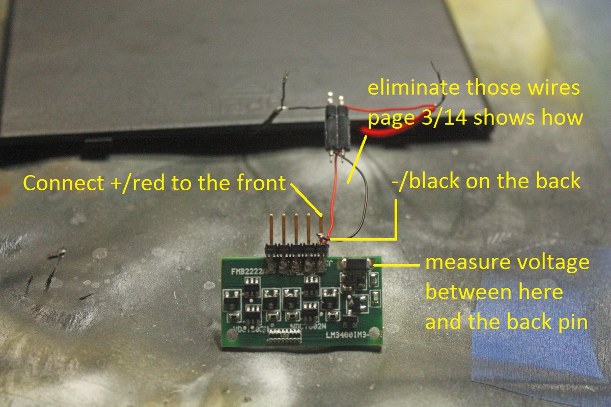
to increase reliability connect the power like shown on page 3 of the instructions - wire the battery pack to the female connector and put the connector directly on the board pins. Saves you at least four potentially unreliable connections. That won’t solve the problem, but will save you trouble in the future. Red wire (+) goes on the front (where the parts are) of the board in case of power and on the back for the LEDs
good news is there’s a hefty diode on the board, so a reversed polarity shouldn’t fry the board as long as the voltage isn’t very high (and it isn’t in case of the batteries you have)
in the photos where you do the measurement the instrument needle hits the right stop - please set it up so as to measure the actual voltage. Set on DC V 50. How many volts do you have? Might help with some troubleshooting.
let’s test that diode (it’s that black brick soldered right to the plus pin). Connect power and measure the voltage between the pad I indicated on the photo below and the bottom pin (-). How many volts do you have?
If you have some spare LED laying around you might check if you can make it light up when you set your meter on R x 1K and touch the long lead with the red probe and the short wire with the black probe. Then you might try checking the LED on the board but you have to be careful here - I would only attemp it if the spare LED you tested just barely lights up.
Let’s see if that helps you. Good luck with your lighting and have a nice day