Just to add a little bit to Pawel’s note on #4, when you select the 50V range, you’ll be reading middle arc of black numbers to get your voltage.
Also, many LEDs are polarity sensitive, so if you test one by applying voltage to it, make sure to put your positive lead on the longer of the two leads on the LED. If you reverse it, it can pop like a firecracker.
Hope you can get it working…the solder joints they put on that board look terrible. I say that because bad solder joints could also be the culprit, and can be fixed if you have good soldering skills. Had exactly that issue on a lighting panel in a 1:1 aircraft a couple of weeks ago. The entire thing would turn on and off on its own when subjected to vibration because the wire was actually floating in the middle of the glob of underheated solder and only making intermittent contact. Its 100% reliable now after removing the solder joint for the aircraft power input, cleaning the solder pad, and then putting a new solder joint in there with proper heat transfer.
If it comes to reworking those solder joints and you don’t want to attempt it, I can probably help you there.
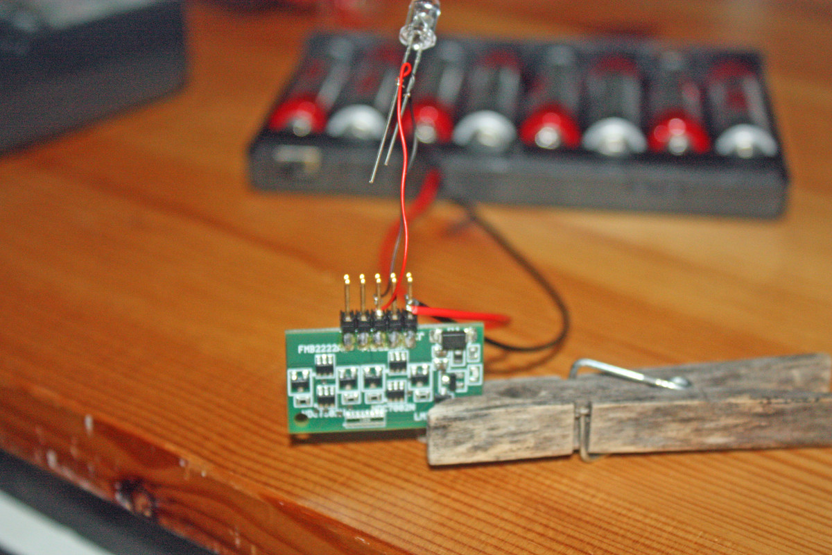
Well, I routed the wires from the battery compartment directly to the power prongs and registered approximately 50 on the DC 50 setting. But I noted that the wires got quite hot to the touch rather quickly, so I didn’t get to testing the direct bulb connection. I suspect I did something incorrectly in this test.
The female end of the connector did not seem to be functioning when I connected that directly to the power prongs.
Now when the wires start getting hot, that’s not a very good sign…
That actually means you got a short circuit somewhere. If you’re lucky, that short circuit is somewhere around the connector - check for wires touching one another, messy soldering shorting two pads or something like that.
If you’re unlucky a part on the board got damaged and is causing the short from power supply (+) to the ground (-) - you can usually identify that part quickly because it smokes
Please check the wires again, they have to stay room temperature.
It might be the resolution of my cell phone causing me to see things that may not be there, but I have a few areas of concern. If you would, Aggieman, please double check the board around the quick connect pins. In your photos, it looks as if there is a yelllowish-green film over the solder joints Again. It might be a problem on my end, but it looks as if you have dried flux pooled into the whole area.
Compare your photo to that which is shown in your instruction manual and you’ll see that their image doesn’t include this apparent stain. Each solder joint is free of discoloration and there are distinct clean spaces in between them. Your photo seems to show that discoloration both on and between the joins. The color makes me think of the residue certain flux pens seem to leave behind.
I only bring this up because some (not all, mind you) fluxes can be electrically conductive. If this is where the power initially enters the board, the pool of flux is also in contact with the outputs. It might not be the source of the shorting that Pawel has advised you on already, but it may be a contributing factor to the problems.
If it is flux, a solid scrubbing with isopropyl alcohol will help to clean up the residue.
Eaglecash also has a point on the quality of those solder joints. Double check them to see if there is any spiking going on. Sometimes with cold and/or contaminated solder joints, the operator will lift the iron away at an inopportune moment, letting the metal form a needle-like spike. If the joints around the power load are spiked, you may have the potential for shorts.
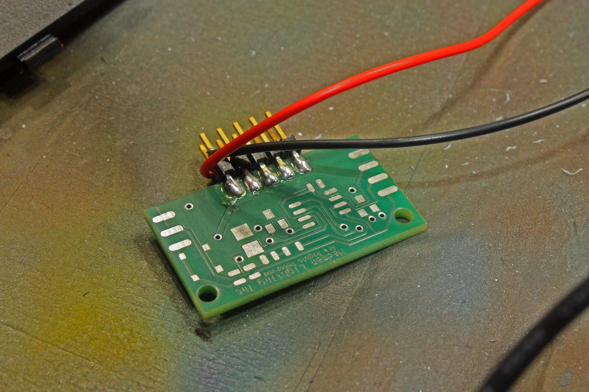
Can you also photograph the back side of the board as well? With as rough as some of those solder joints look, I’d be curious to see if all of the components are properly mounted and the solder points sufficiently wetted.
The wires getting hot can also be caused by the high resistance of bad solder joints. I agree with KnightTemplar about the flux as well…there are some of them out there that are conductive. When I clean flux from a solder joint, I have found that denatured alcohol works really well, along with an acid brush (don’t worry, there isn’t any acid involved, they’re just called that). The lead on that header all the way to the right in your pic really jumps out at me now. It looks like its a cold solder joint where the header and the board aren’t actually solidly connected electrically. I can see the square header lead in the center of that globby, grey solder joint. You shouldn’t be able to see that. That comes from insufficient, uneven heat transfer between the two components being soldered. A high resistance connection like that can generate a lot of heat. I’ve actually seen holes burned through aircraft skin that were caused by loose terminals on electrical buses…also have seen lots of melted static system tubing caused by the same thing.
Honestly, at this point, I hope that you paid for that through Paypal so you can file a dispute. The amateur who made you pay $69.00 for that monstrosity shouldn’t get to keep your money.
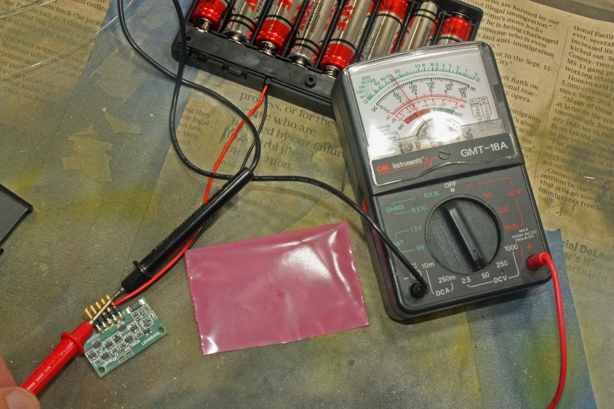
I cleaned up the exposed wiring and reconnected, ensuring there was no contact between them. No heat this time, so I am guessing that was the cause of the heat in my last test. I confirm power registering on the board’s power prongs, but it still does not light an LED.
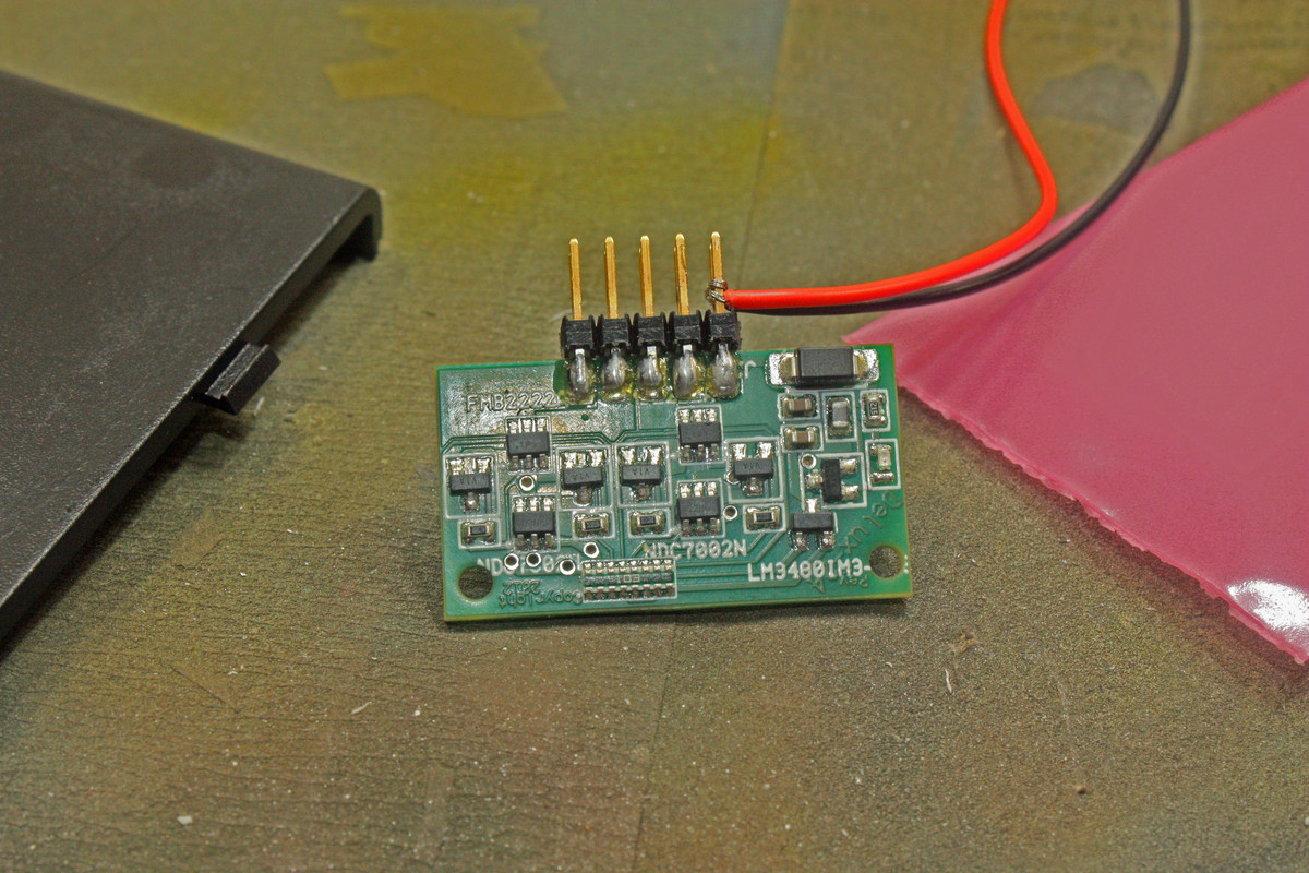
Latest photos:
I don’t see any evidence of the greenish film but then I probably don’t know what I’m really looking for.
I’m thinking I have a lemon here. I’ve reached out twice to the manufacturer but still have heard nothing back from them, not even an acknowledgement of receipt of my communications. They are about to receive a very unfriendly review.
Unless y’all see something else in these new photos, I’m likely to move on by rigging everything without the circuit board, running wires to LEDs and resistors, etc.
Yes, I did pay for this through PayPal. I looked at the transaction and noticed a different e-mail address for TenaControls than what they list on the MadManLighting web site. I just sent out another communication and gave them a deadline to respond; otherwise I will request a refund through PayPal and leave negative reviews of both the company and their products.
Yup…looks like you’re definitely getting good voltage out of your battery box. I see about 13.5 volts being indicated on your meter. I think you’re right about it being a lemon. The flux that KnightTemplar mentioned is the kind of yellowy, shiny stuff on almost all of the solder joints on the board. Its probably soft and a little tacky to the touch. That stuff shouldn’t be there. Its a component in the solder (and it looks like they used really low-quality solder) that aids in heat transfer, and after the solder joint is made the flux is supposed to be cleaned away. Its also a little strange that all of those surface mount components appear to have been soldered to the board using a regular soldering iron. The problem with doing that is that only one solder joint at a time can be made on the component, and when one side is firmly attached with the first solder joint, the pressure applied for soldering the other contact often causes the component to crack internally and stop functioning. A proper surface-mount soldering iron has a tip that spans across the top of the component so the solder joints on both sides are made at the same time…and its usually best done by a machine. Its really difficult to do those by hand and not screw something up.
OK, the wiring looks a lot nicer now… Out of curiosity, could you check the voltage behind the big diode? That would mean repeating the measurement you show on the last picture, just move the red probe to the pad on the right side of that diode (like I shown you on the picture I posted previously). It might also be interesting to measure the voltage across the little LED (one probe on one side of the LED, and the other probe on the other side - maybe the LED is bad?).
I did do that as well but didn’t get a photo. The voltage was the same. I didn’t think to try that with the LED, so I will do so later today and get photos to post.
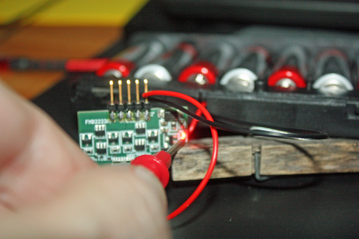
So the LED does actually work. Instruction photos show it to be a green light, but this one lights up red. But, I was able to get it to light with only one prong from the voltage meter touching it; it also worked with both prongs but given that people only come with a maximum of 2 hands, I couldn’t hold both prongs and get the camera into position, let alone in focus. Even with only one prong, I still had some difficulty with the focus, but you can see that the light is glowing.
On another note, the TenaControls owner has responded to me. I will respond with an explanation of what I’ve done to get it to function to this point and see what he comes back with.
I also notice that when I touch the volt meter prongs to the prongs on the board where the LEDs are to be connected, the result is the needle moves off the scale to the left, as in a negative reading perhaps.
So there’s progress! Shitty one, but still progress. Do I understand it right that the LED lights up when you touch it? If so, then you have a bad soldering on it, exactly like Eaglecash867 explained it. That’s bad, because now you can’t be sure of the other soldering joints on the board - what if something else doesn’t work, too - then you would have to check and maybe resolder every component of that feature… Lots of unnecessary work.
Not sure about that LED you hooked up, but did you notice the instructions say that on the power connector the red wire goes to the front pin, but for the LEDs the red wire goes to the back pin?
I sure do wonder what the company is going to tell you. Here in Poland we have a joke which I’m going to make family-friedly: For 70$ that board should bring you breakfast every morning!
Depending on how you have your meter set up, the LED coming on when touched with a meter lead isn’t necessarily an indication of a bad solder joint in that area. Meters produce a small amount of voltage to conduct resistance measurements, so it could just be that causing it to light up. I was using my meter at work just yesterday to move a 1:1 aircraft’s glideslope needle up and down to check it for high electrical or mechanical resistance. When set up to be an ohmmeter, I could actually get half-scale deflection, which takes about 1.5 volts to accomplish.
Hopefully the Tenacontrols owner will be more responsive now and get you fixed up.
Pawel, there’s nothing wrong with a $70.00 price tag on something like this if it does what its supposed to do and its made of high quality components. Things like this take a lot of time to develop for a given application, and people can’t run a business by donating their time. We can voluntarily donate our time here to help fellow modellers, but businesses can’t do that for us and still be around when we need them later. The guy over at Falcon 3D Parts charges a lot more than 70 bucks for his lighting kits, but I don’t have a problem paying it because his work is absolutely superb. Sorry for the OT, this is just kind of a sensitive subject for me. I’ve seen a lot of good people in my industry lose their life’s work because of all of the people in the world that don’t think that someone should be allowed to make money. [H]
The owner did reach out to me. He suggested to me exactly what Pawel points out - the LED’s longer post should connect to the back side of the board. So I did that with that one bulb I had been using, and nothing. I attached a different bulb and got glorious blue light!
So it would appear I have one bad bulb.
I remain a bit concerned over what y’all are seeing with regard to potentially bad soldering, though.
I figure I’ll hook everything up, including running all the fiber optics, and not mount anything in a permanent fashion, and see how it all works. Testing along the way. Something I have noticed is that even when these leads are attached via this wire wrap tool, they still can come loose. Should I go ahead and solder those? Soldering is not something I’ve done a lot of in recent years, but I figure I can at least get the wires to remain where they need to be; might not be pretty, though. I’ll need to do a good bit of practicing on non-working components before working with the live ones.
And to echo Eaglecash, I really did not want to bomb this guy with negative reviews and demands for a refund. For the very reasons that he cites. I would have had he not responded, but it wasn’t going to make me happy. Scale modeling is a tough enough business to stay in, as I imagine it is for this type of electrical component products, so I’d rather not be one who would contribute to anyone’s business failing (I recognize that my “responsibility” for that failure would be only a minimal part of it, with most of that falling on the owner/proprietor).
If y’all have any further suggestions, please let me know. But a big heart-felt thank you from Texas![:D[
As far as the wires and the leads go, what I would do if I was in this situation is to actually desolder and remove that header (the group of leads). Headers really only serve a useful purpose when you have a mating connector that slides onto the header. After the header was removed, I would then solder the wires directly to the solder pads that correspond to the header pin that you would have attached them to. But, if you don’t want to do that, then soldering the wires onto the header pins is a perfectly viable alternative…just not as tidy. Another thing that I would be concerned about is the quality of the board. Some are better than others, and there are some that, no matter how careful you are, you end up pulling up pads and tearing traces. So, removing the header could easily end up destroying what you’ve already put so much effort into.
You could also look around at on-line electronics suppliers and find the mating connector for the header, but those tend to require special crimpers to get the contacts onto the wires
Edit: One more thing on soldering the wires. Just make sure to give those leads a good scrubbing with ScotchBrite or something similar to remove any oxidation/contamination on them. That will make the solder flow better. Its also helpful to brush a little flux on those leads to help with heat transfer.
Eaglecash867 - OK I understand everything needs time to develop and everybody needs to eat and somebody has to pay for it - that’s all perfectly clear. I also have paid a lot of money for hobby items, sometimes the buyer jus says “it’s worth it for me” - I’m perfectly OK with that.
It’s just that when you compare a consumer market device you buy for 70$ - like for example a smart display with built in artificial intelligence personal assistant - with this PCB and a bag of parts we’re talking about here… I start getting a feeling that something’s not OK here.
It starts looking like you could achieve the same task using off the shelf components from a chinese supermarket for a fraction of the price and maybe get some nice features on the way like controlling the lighting of your model via Smartphone/Bluetooth or over network/WiFi/IP. Dang, some days ago I personally bought a development board that can drive over 10 LEDs and has WiFi connectivity for under 10$. And it worked and was properly soldered. If I connected this to an USB charger (and you know how expensive those are) I would need to add some fiber optics and LEDs and I would still have some money left for a nice lunch.
OK - somebody might say: I want to pay the money and not worry about looking for components, integrating everything and so on. Like shown in the posts above this kit doesn’t really give you that neither.
All that ranting slowly makes me think maybe I should bring out my own lighting kits that would make this Madman kit like a museum item? Yeah, I know I’m just flapping my mouth right now, it’s just that there’s visible room for improvement here.
Two things that bother me the most about this PCB are shabby soldering, and irrational design with that unexplainable power supply… 12 - 18V??? Why? Is your other business an AA Cell factory?
Allright, rant off - thanks everybody for reading and have a nice day
Pawel, in this particular case, I agree with you. The shoddy workmanship that we both noticed makes the lighting kit worth far less than what the guy is asking for them. Its really strange that there is such a difference between the pictures in the instruction manual and the actual item itself. It did seem that your criticism of the cost was more of a generalized statement and not just about this particular, low-quality product though. If that wasn’t the case, I apologize for the misundertanding. My nerves were a little raw from an experience I had earlier this week with a customer who was very upset with me for not working more than 11 hours a day and diverting my attention from 2 big projects I’m running for the Colorado State Patrol just to give her a quote for installing a cheap EHSI and NAV/COM in her Piper in the amount of time she’d like one. I’m having to work as much as I am because I’m pretty much all that’s left in my area…everyone else went out of business bending to the demands of penny pinchers. [bnghead]
I understand the quality thing though, so I’m right there with ya on that. I would have been absolutely livid if I gladly paid 70 bucks, and that was what I got in the box. I see the same kind of thing in the world of after-market resin kits. Many of them are really amazing quality, and some are just plain garbage…yet the guys making the garbage want to charge you the same price (sometimes more) as the guys making the good stuff. Sometimes, if you give an honest assessment of a garbage resin product, there do tend to be some modellers that want to run you out on a rail…so the garbage never improves.