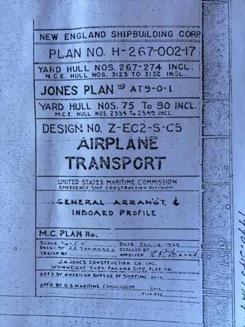
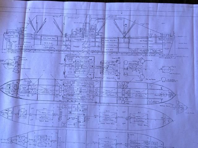
I’m making a start on the Frank O. Peterson, Liberty Airplane Transport, from the Trumpeter JOB 1/350 kit. My father was Radio Operator on a trip to Biak in 1945, carrying P-38s. These were late war builds and modified with larger hatches and different cargo gear to carry aircraft. The differences from the JOB kit that will have to be changed are the cargo gear and hatch arrangement. There are three large hatches and one smaller one aft. It’s all kingposts rather than single masts, no heavy lift. It seems the winches are electric rather than steam. There are two longitudinal stiffener beams on deck. The armament looks to be the same as the JOB. The liferafts forward are the same, but there is a stack of floats aft by the 5" gun rather than the big floats aft. The plans don’t show it, but photos show more windows in the wheelhouse rather than the three small windows. My Dad confirmed they only used the wheelhouse as a bridge rather than the one open to weather at the top of the house.
I’ve been meaning to go on google earth to see if I can find any remnants of the dock at Biak. Dad only recalls it was parallel to the shore line and near the airstrip. He doesn’t remember if it was pilings or cement or what. Maybe it was steel floating sections? If I can’t find out I’ll do it as pilings. Having nothing to do in port at Biak, Dad walked to the airstrip and bummed rides on B-25s and B-24s and went sight seeing over the jungle of New Guinea.
There was one air raid alert while he was there, and everybody who was unloading bombs from the Liberty at the dock with him ran for their lives. All the Japanese planes were shot down before they got close.
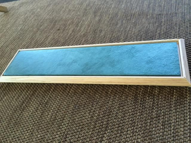
I’ve started on a water base. It’s plaster poured over pebbled bathroom glass as a mold, painted with acrylics and coated with Future. It’s supposed to look ‘tropical’.
Thanks for that Ed. Floating docks would make sense to me given the time and place. But I just consulted with my 88 year old eyewitness and he is sure it wasn’t a floating dock. It was a dock parallel to the shoreline long enough for two Liberty Ships. I also took a reconnaissance flight over the south and east coasts of Biak via Google Earth ( what a world we live in!). Just off the modern airport is what looks like a long submerged causeway going perpendicular to the shore. Dad says that is not familiar either. So i guess I’ll go with pilings.
Do you have any transport photos etc.? Great project!
Those drawings remind me of my only visit to the JOB.
My daughter was dating a guy who was a volunteer steam engineer on her. He did all kinds of stuff to get on my good side- pieces of plate and cable, and a tour behind the scenes in the engineering spaces.
He got a big kick out of the bubble levels built into their big lathe, useless as anything.
My daughter had been on board before and was eager to get me to go down the shaft tunnel to the end and back- oh hell no! That one lonnng shaft!
Did she have those big racks on deck, or was it all in the holds?
When I was on the JOB years ago they had the engine turning over slowly. On the big crank shaft they had a plunger that went up and down in a 55 gal drum, their laundry machine! It was interesting and discouraging that the bridge and quarters were very familiar to me. I could test gear and sail with almost no orientation, in 1988.
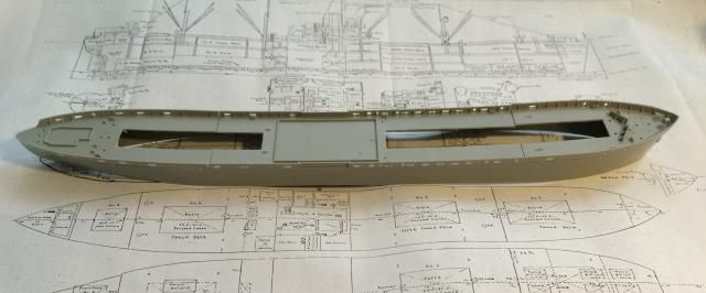
Dad says all the planes were below deck on his trip. I’m going to have all or most of the hatches open.
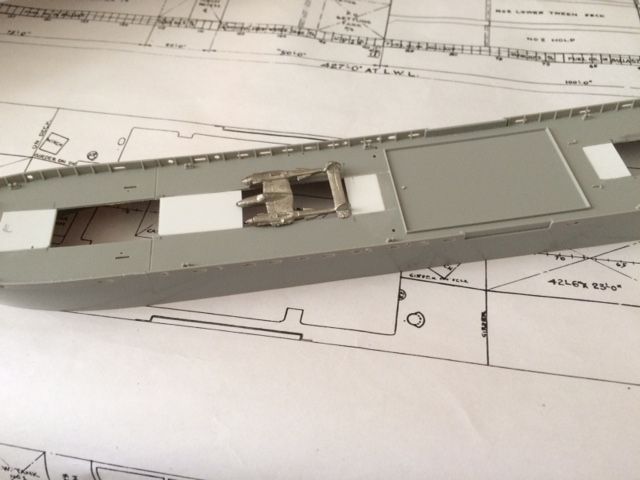
Hatch openings are roughed out. They’ll be a little wider than shown, but you can see that getting a P-38 in there required some careful stevedoring! It’s so tight that I checked with Dad to be sure the planes were whole, minus the outer wings. He said they were. Looking at this, it seems the best use of space would be to stow them nose/tail athwartship. Doing that, I can see you could get about two dozen aboard.
Hatch coamings done and kingpost assemblies started. There is this strange system of girders on deck. I suppose the holds are so large they needed extra stiffening. I must say, the fit on this Trumpeter kit is not nearly as good as it was on the first one I purchased some years ago.
But in a slightly more intelligent vein —GREAT Job! on your work so far this is a good example of how to: model the model you want, from the model you have…
This is a cool project. I think L’Arsenal has some shore (piers, pilings, moorings, etc.) stuff but can’t remember the scale if that helps at all. I’ll be watching this one!
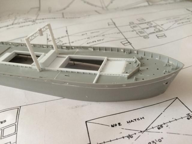
Thanks everyone! As I get along on this I see why they needed those girders on deck. Usually the hold would have columns inside. But they had to have large open spaces to get the big planes in there, so the strength had to be on the outside.
That makes sense. It would be faster to cut where needed and add where needed than re engineer the design. Not elegant, but effective. That had to make the deck detail miserable though.
I am amazed that those Lightnings could get below. And I agree there’s not really any more disassembly possible than shown. Would involve a lot of tipping, tilting and probably shouting. But without wings I think they’d weigh less than 10,000 pounds.
Less than a big 6x6.
My father in laws squadron was issued P-61s in Italy in November 1944. For the ocean voyage they had all of the open joints between the airframes and the movable (all metal) control surfaces thaped up. When that was stripped the black paint came off too. Really looked like hell. Just like a bad day at the bench!
I just resolved the one detail I had doubts about, the number of windows on the bridge front. The plans don’t show them, but grainy pictures showed more than the three small windows that the JOB kit has. On Navsource there are plenty of clear pictures of these ships in their later careers as radar picket ships. The Frank O. Peterson became the USS Scanner. It turns out they had a line of portholes, not windows, all the way across the bridge front. All the pictures are from the 1950s, but I am going to assume this detail was not changed in the conversion. If they were going to change anything there they would have made them windows, not portholes.
Looking at these plans ,can you see where the Liberties had an inherent problem ? You do know of course that some of these as well as the regular Liberties developed a problem of snapping in two just forward of the Deck-house in rough weather , especially if loaded to their maximum planned gross weight . T.B.
I believe that problem was with the welded construction, not anything to do with the design per se. I recall something about putting riveted doubler plates in certain points to stop cracks from traveling, and that fixed the problem.