Kodak Olds NASCAR Racer Start-to-Finish Build

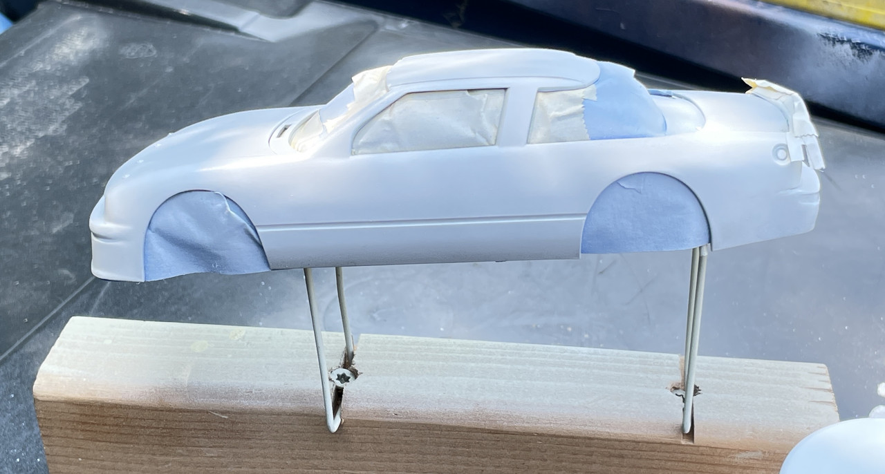
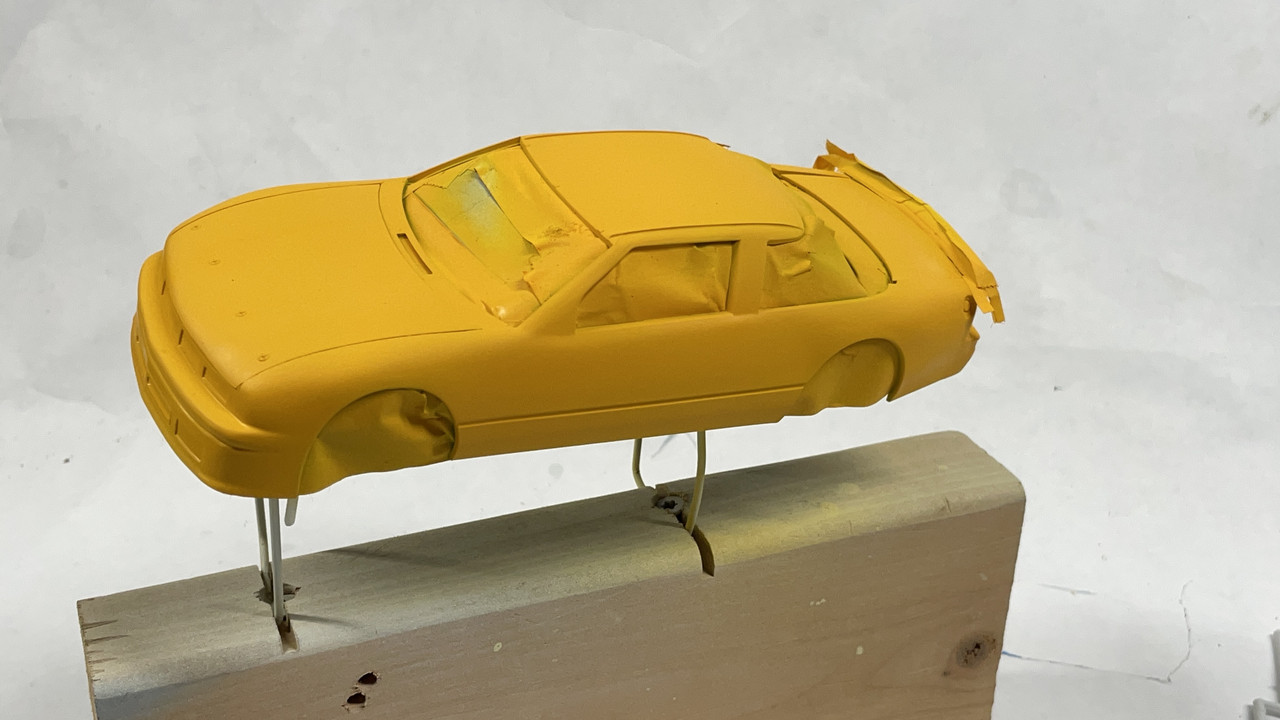
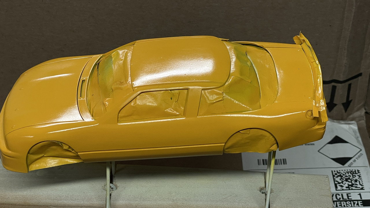
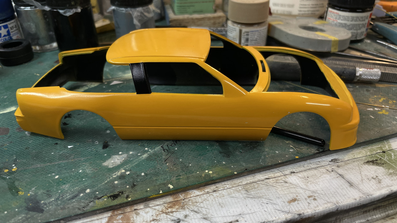
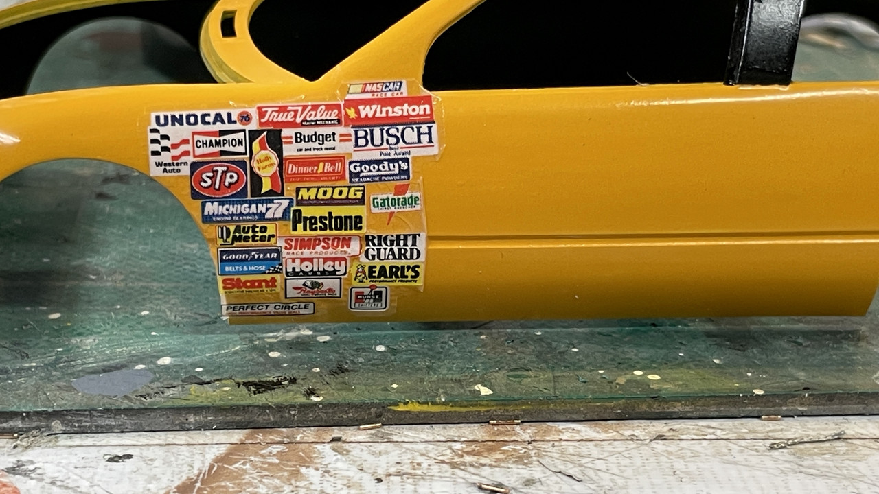
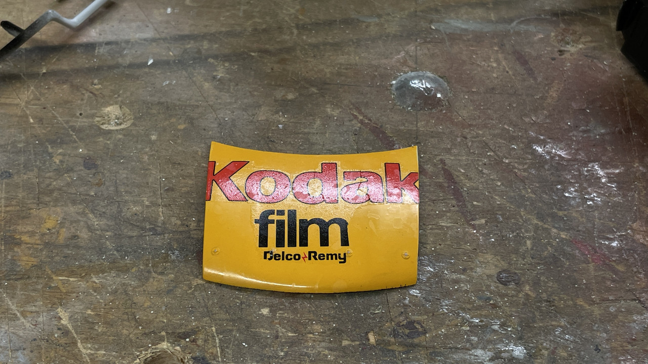
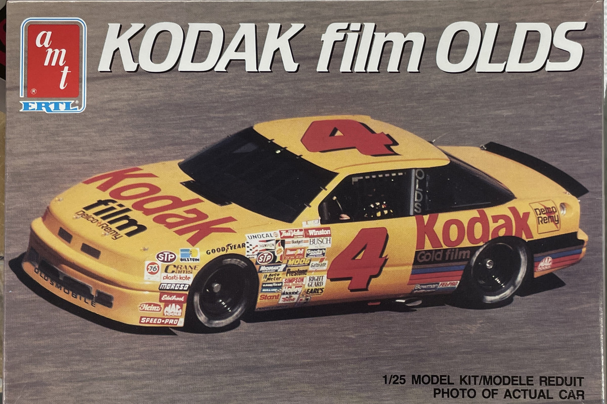
Our Louisville, KY model club, Military Moderlers Club of Louisville, is holding a mini-contest in July. The subject of this one is any kind of four wheel racing vehicle. I had won this AMT/Ertl Kodak Oldsmobile 1980s vintage NASCAR racer in one of the club’s usual end-of-meeting raffles. I generally don’t build cars since they don’t offer enough challenge for me, but with the upcoming contest, I will give this one a shot. I find that the older car kits just don’t have the brilliant molded-in details that modern kits by Tamiya, Meng, or Takom is currently producing.

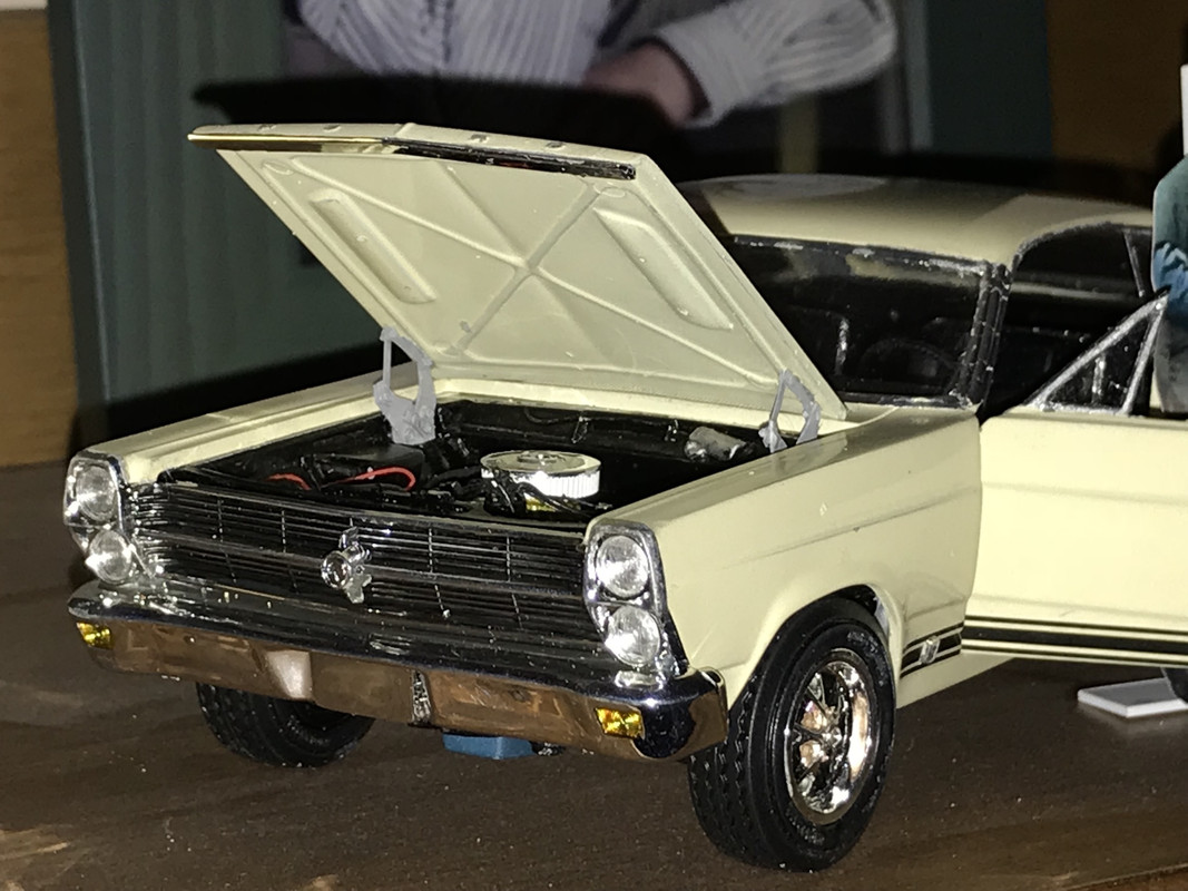
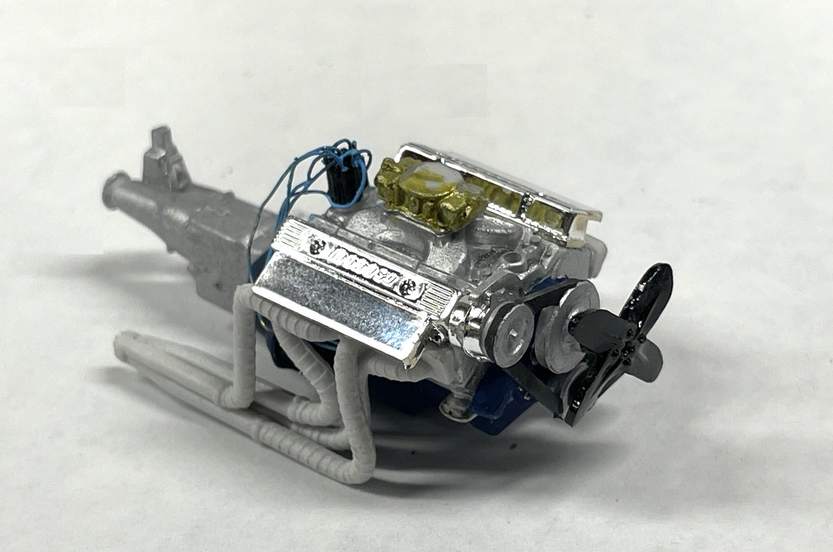
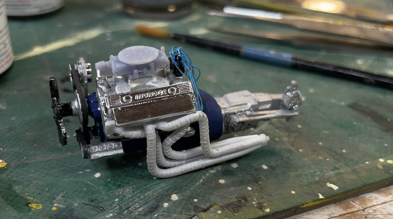
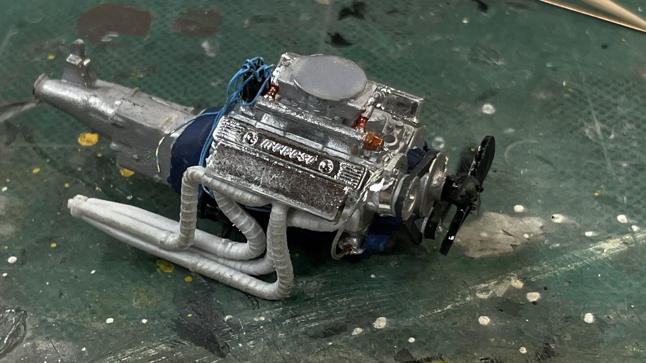
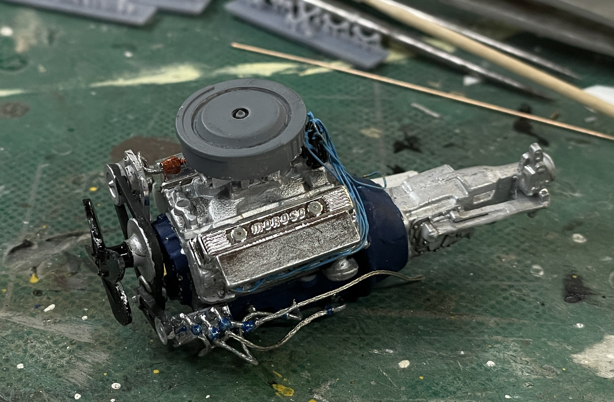
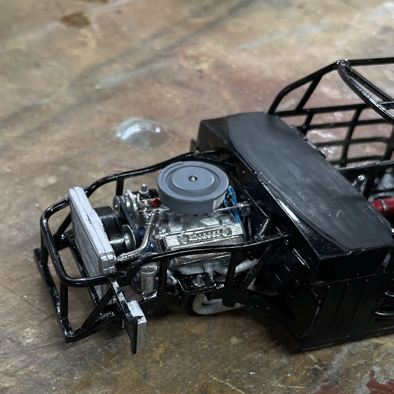
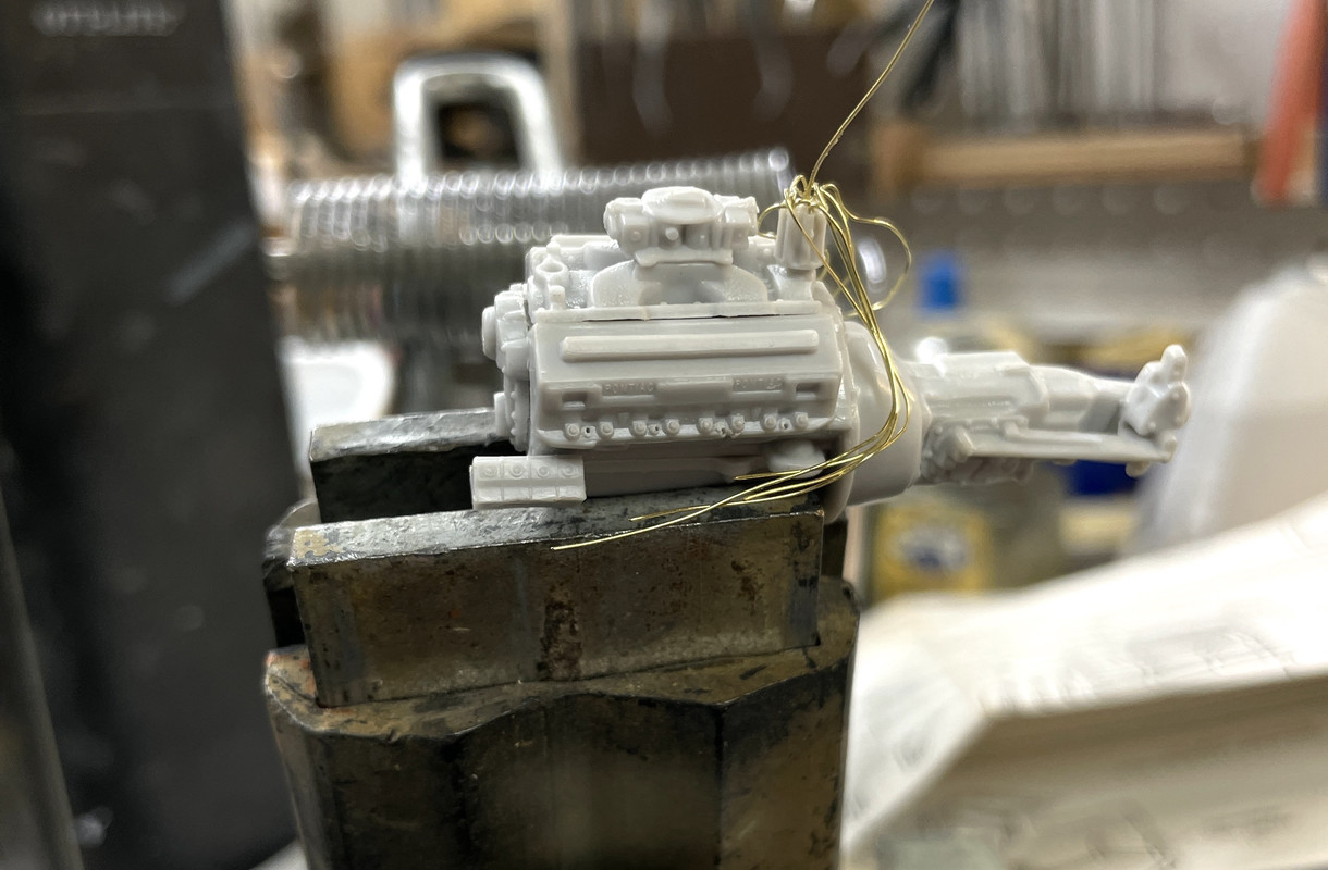
I already ran into difficulty in building the engine. The positions of the spark plugs is ambiguous and is partially blocked by the exhaust headers when they’re installed. I’m using some .012" brass wire into holes drilled by a similarly-sized carbide drill for the ignition wiring. I pre-placed all the distributor wiring. I’m not concerned about getting the firing order correct since I don’t know it. I am alternating them from left and right block sides.

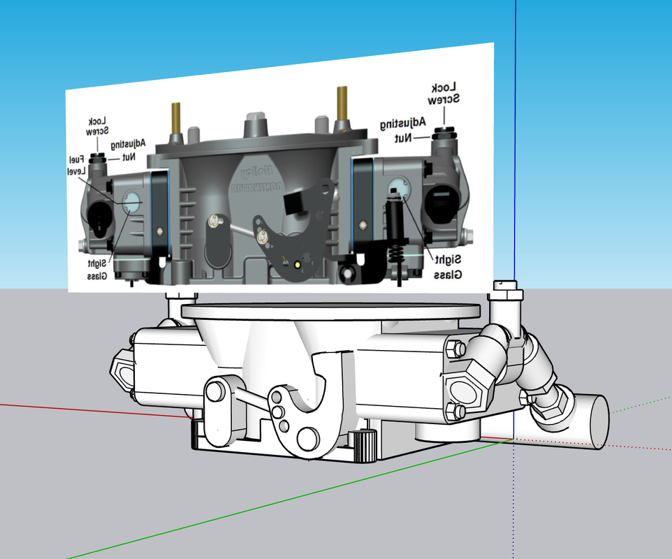
The carburetor, while looking like a Holley, doesn’t appear to be correctly shaped for a NASCAR engine, nor does it have the spacer block beneath it and between intake manifolf. The contest winner will be determined by voting by the members and I doubt they’ll be that specific in their discernment.

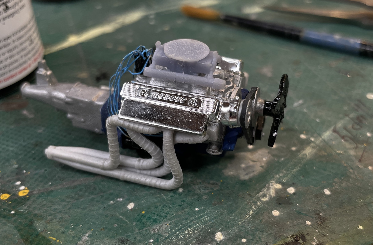
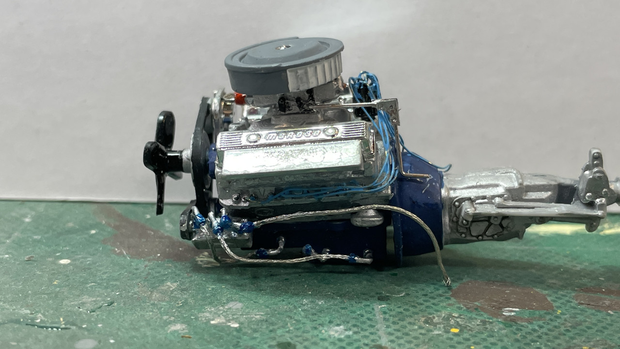
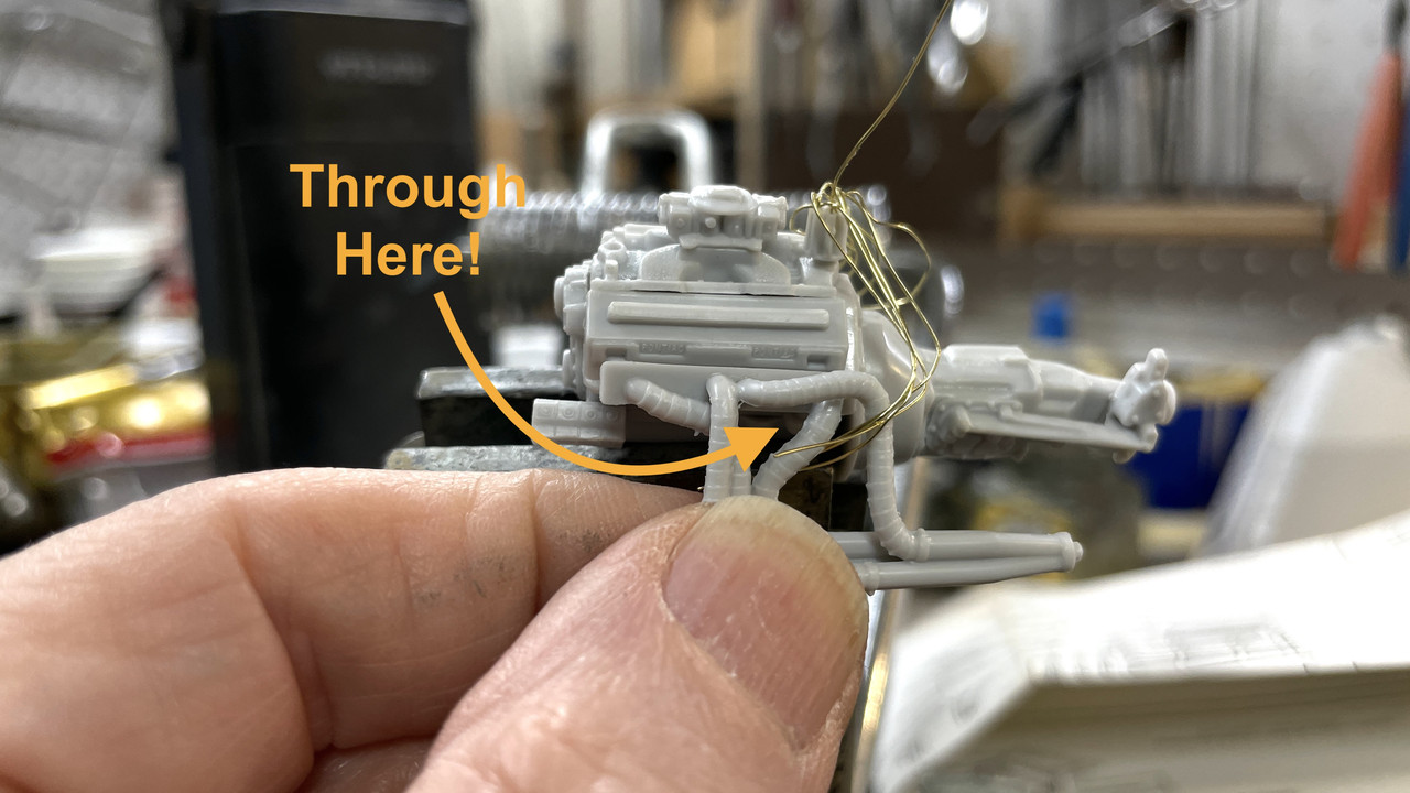
In this image, I’m holding the header near its final position and you can see that it obscures the access to those tiny plug opernings. Having to thread the plugs leads through the headers is why I haven’t terminated them into the heads. I have to wait until the engine is assembled and painted.

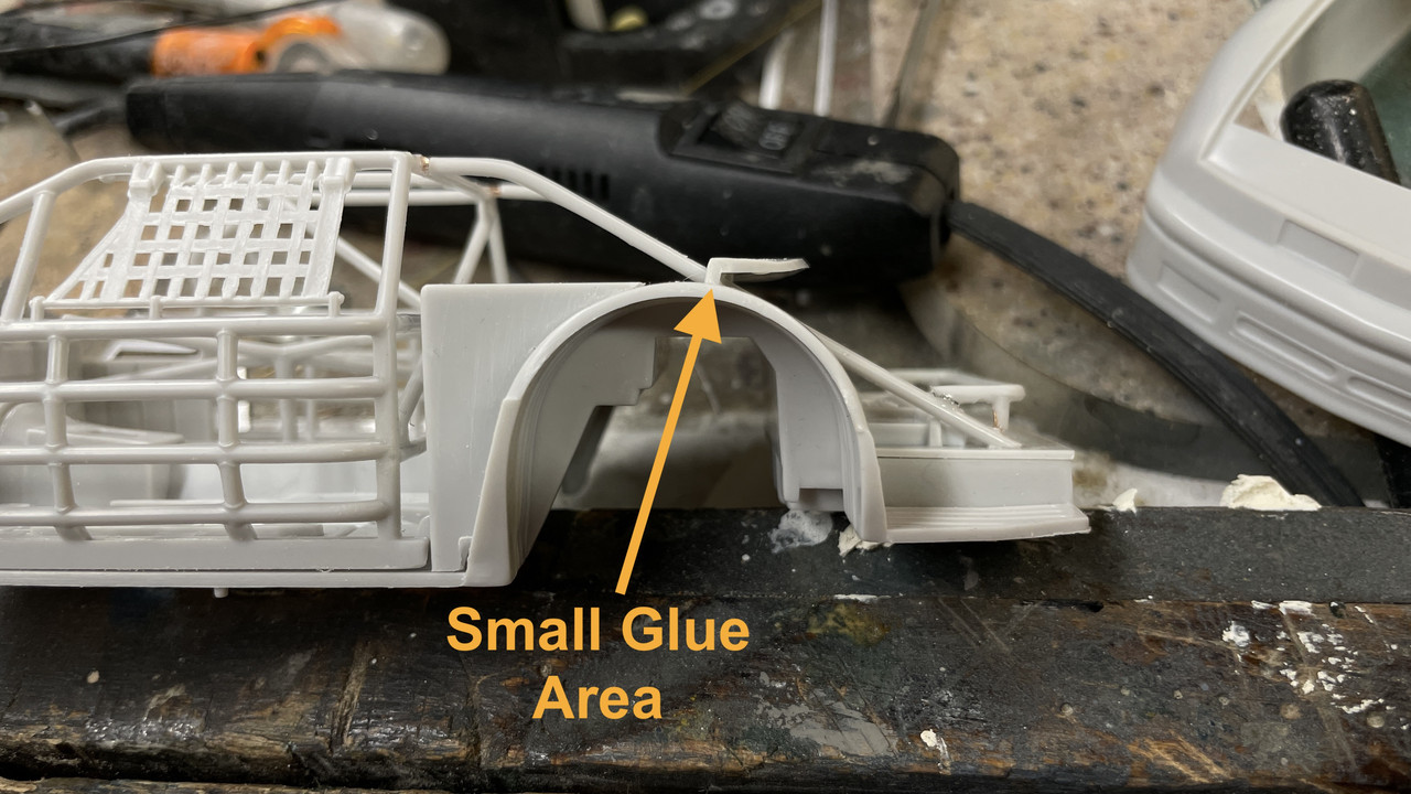
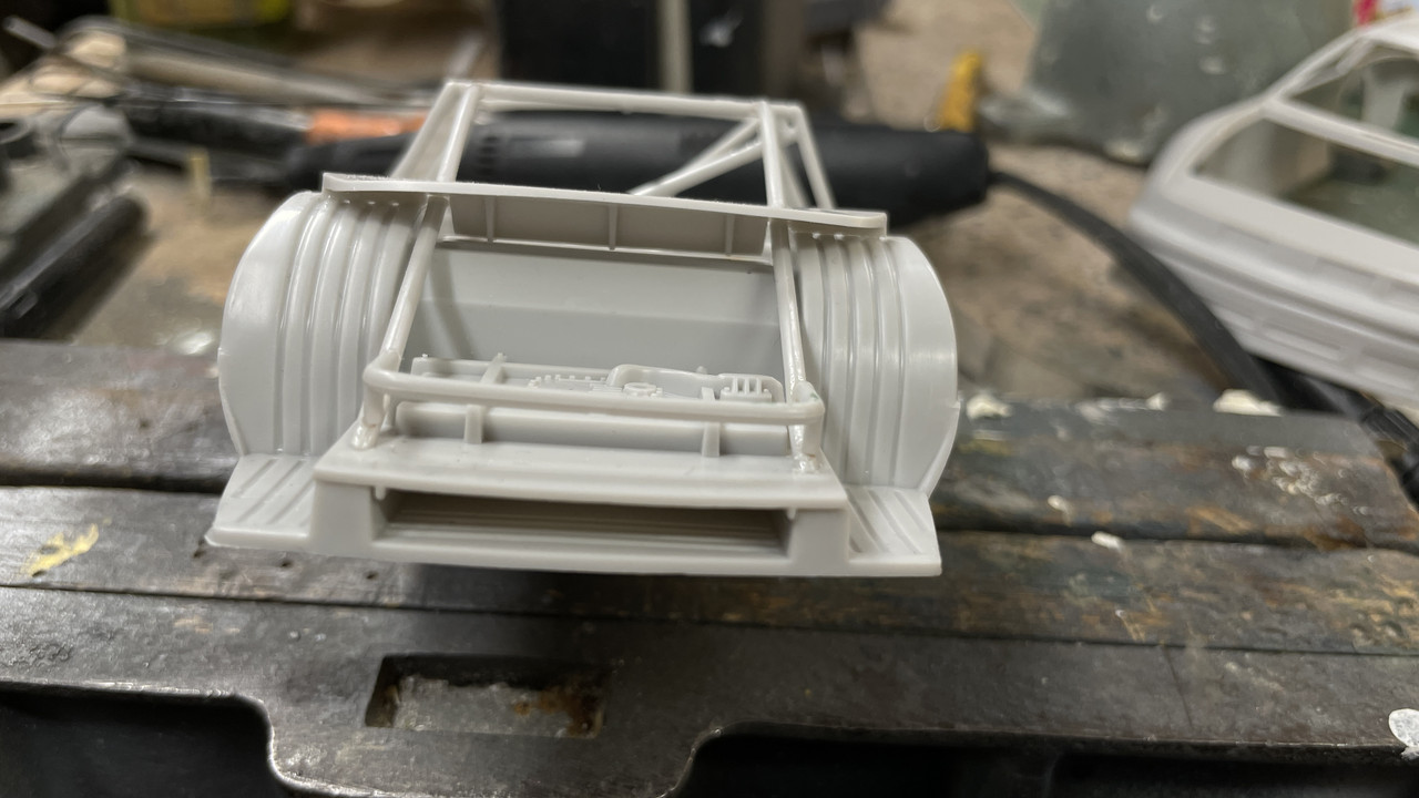
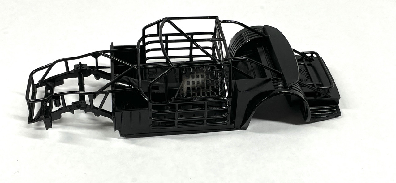
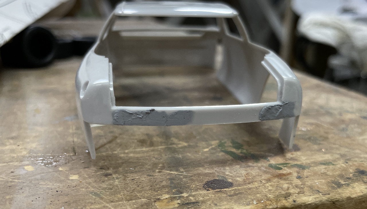
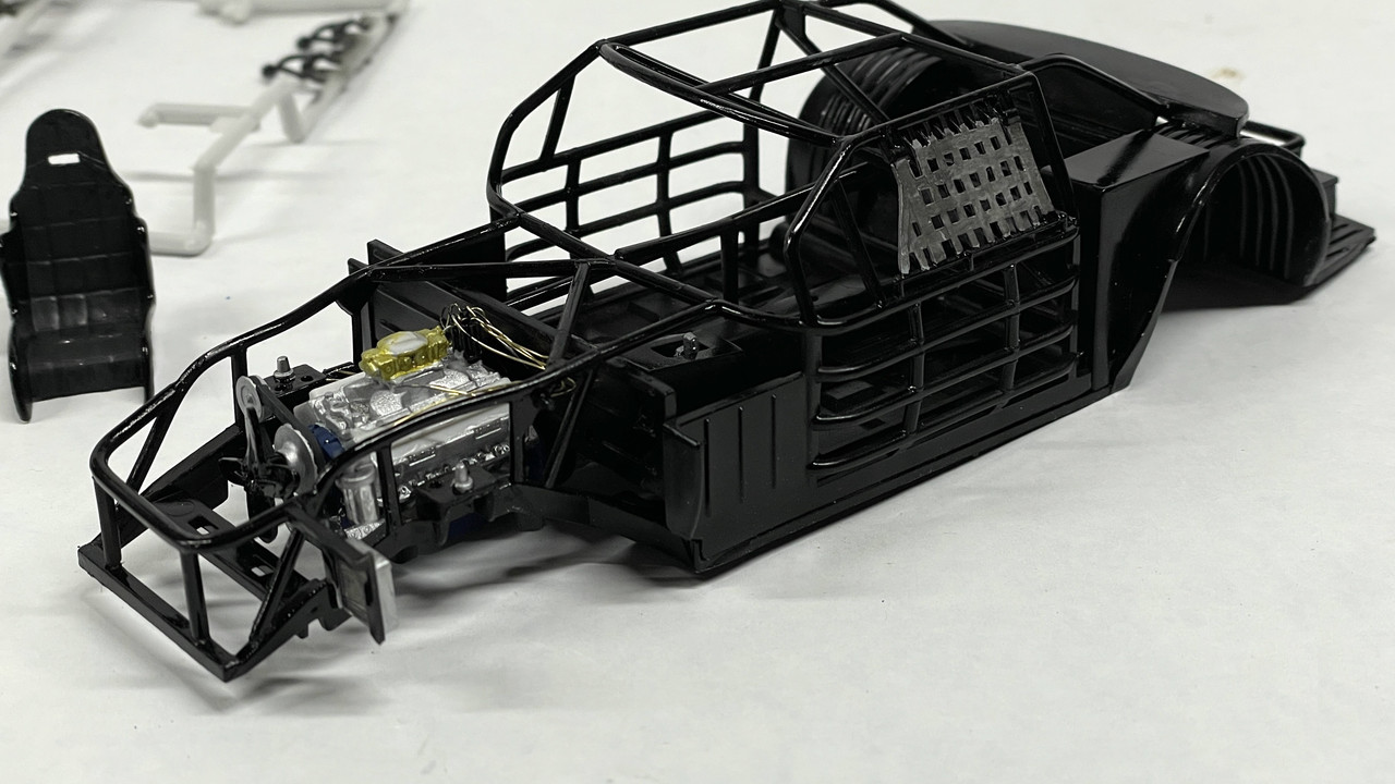
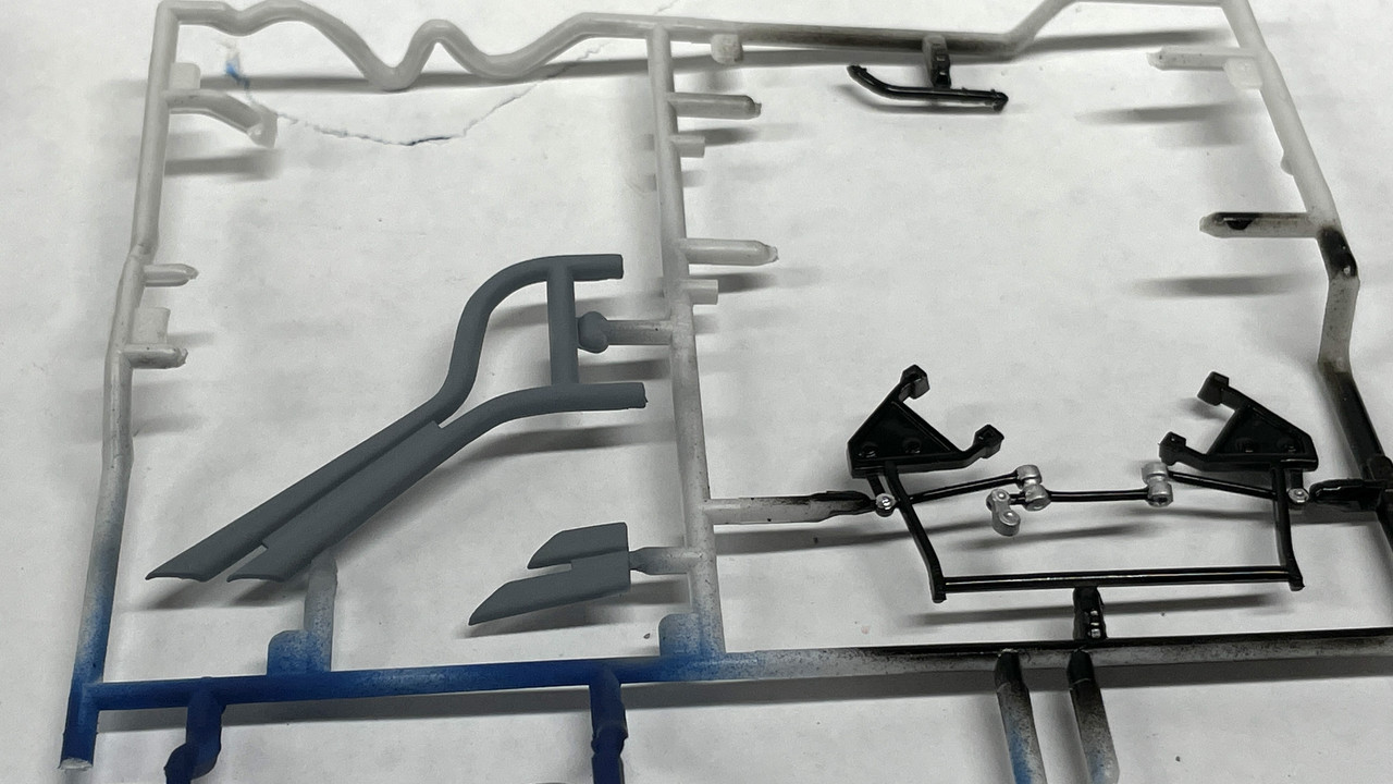
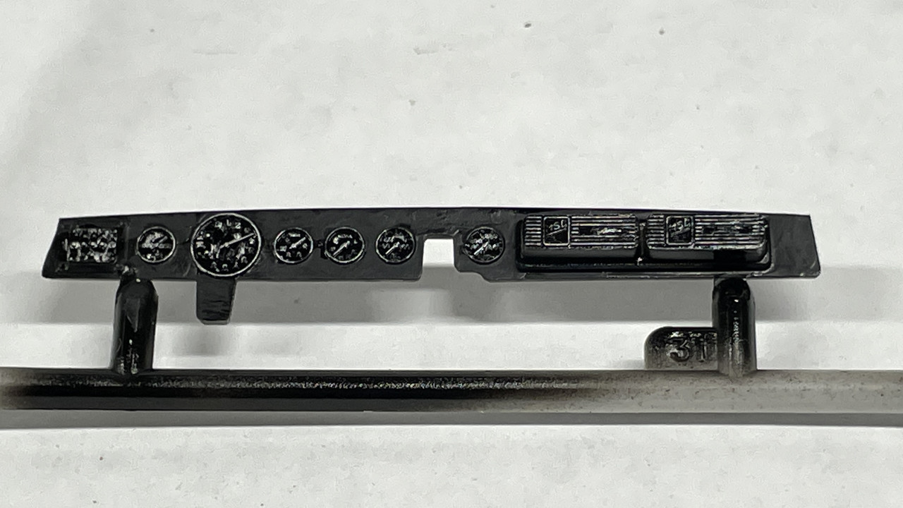
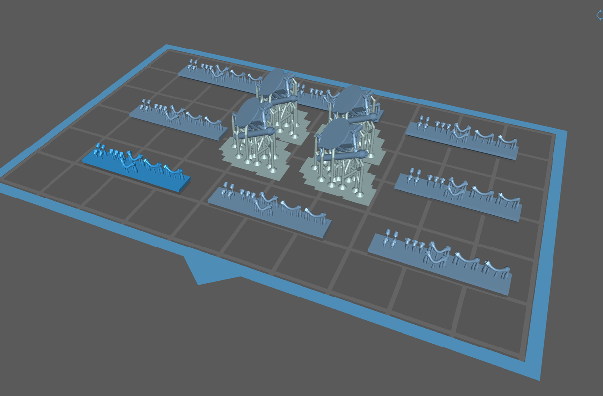
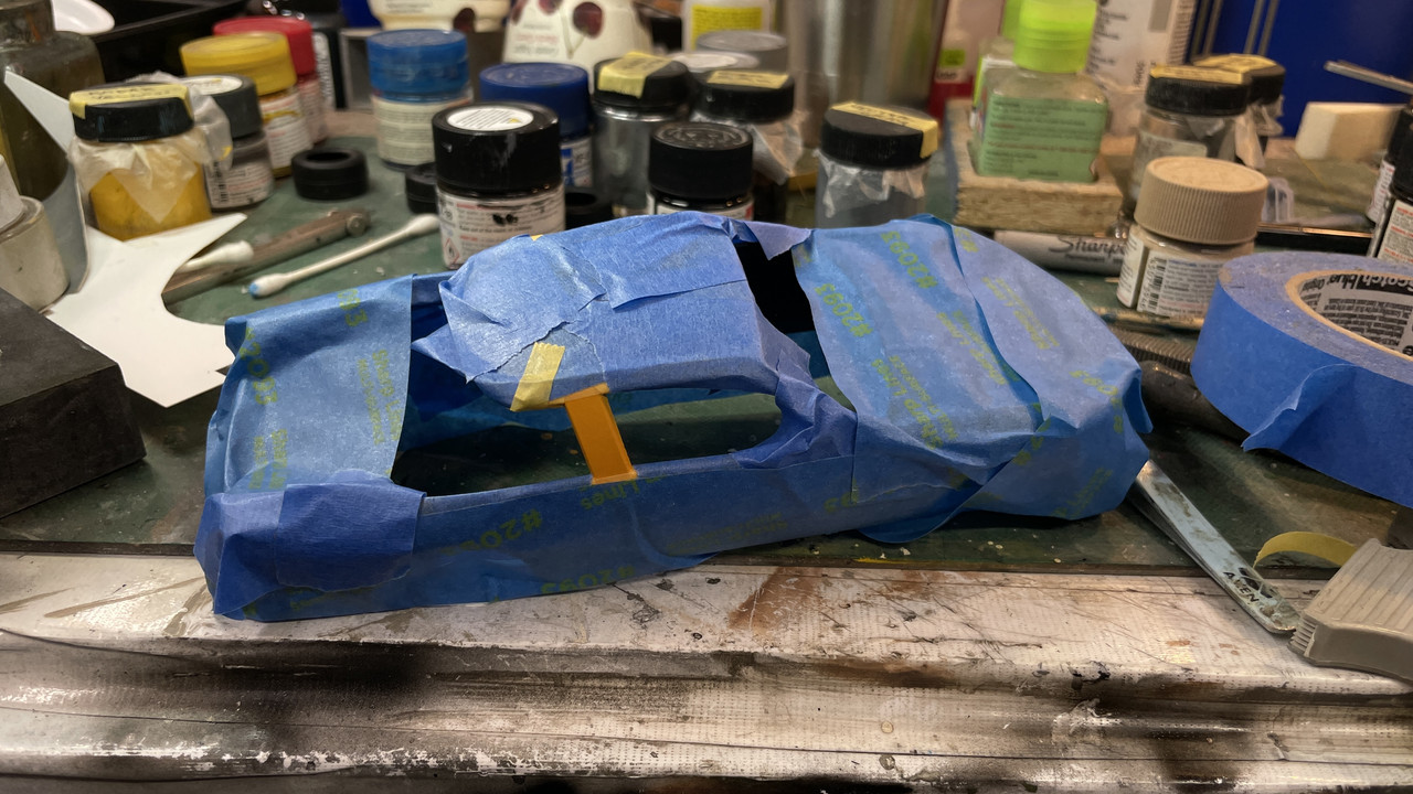
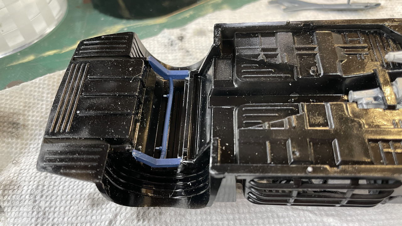
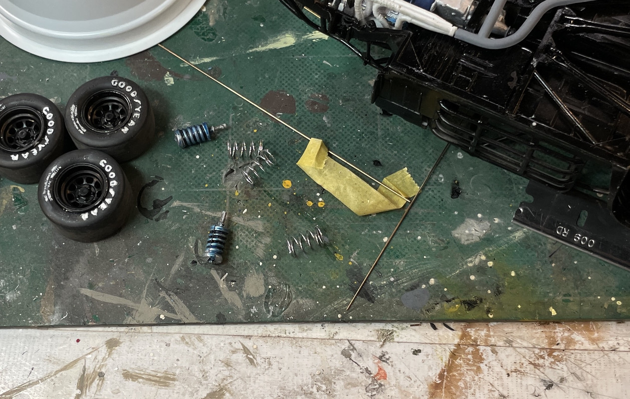
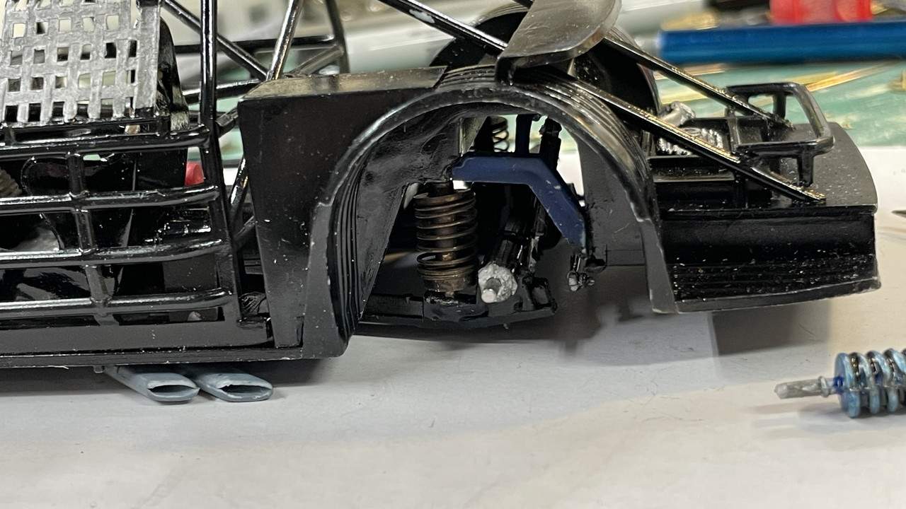
Leaving the engine aside I started building the chassis and roll cage. The entire assembly is gloss black so I’m assembling it all and will airbrush it as a complete assembly. I tested to make sure I could get the instrument panel and seat in place before doing this. Painting all this before assembly would just make a headache trying to get those tiny glue spots to fuse properly with paint nearby.

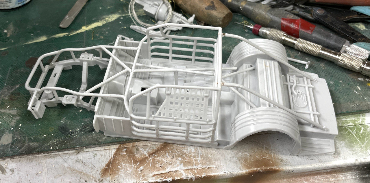
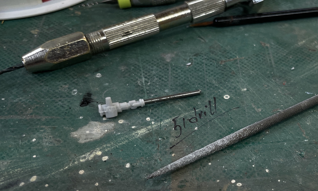
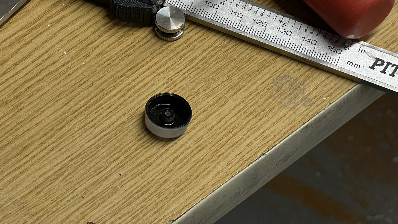
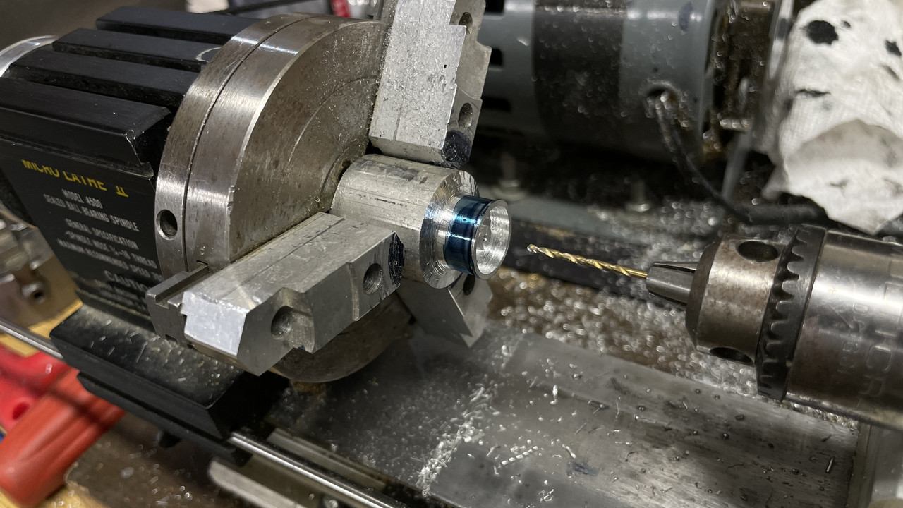
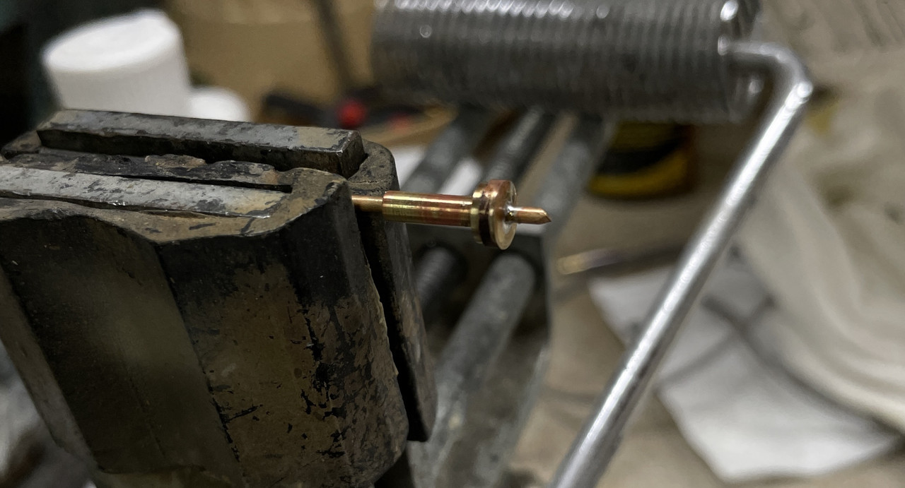
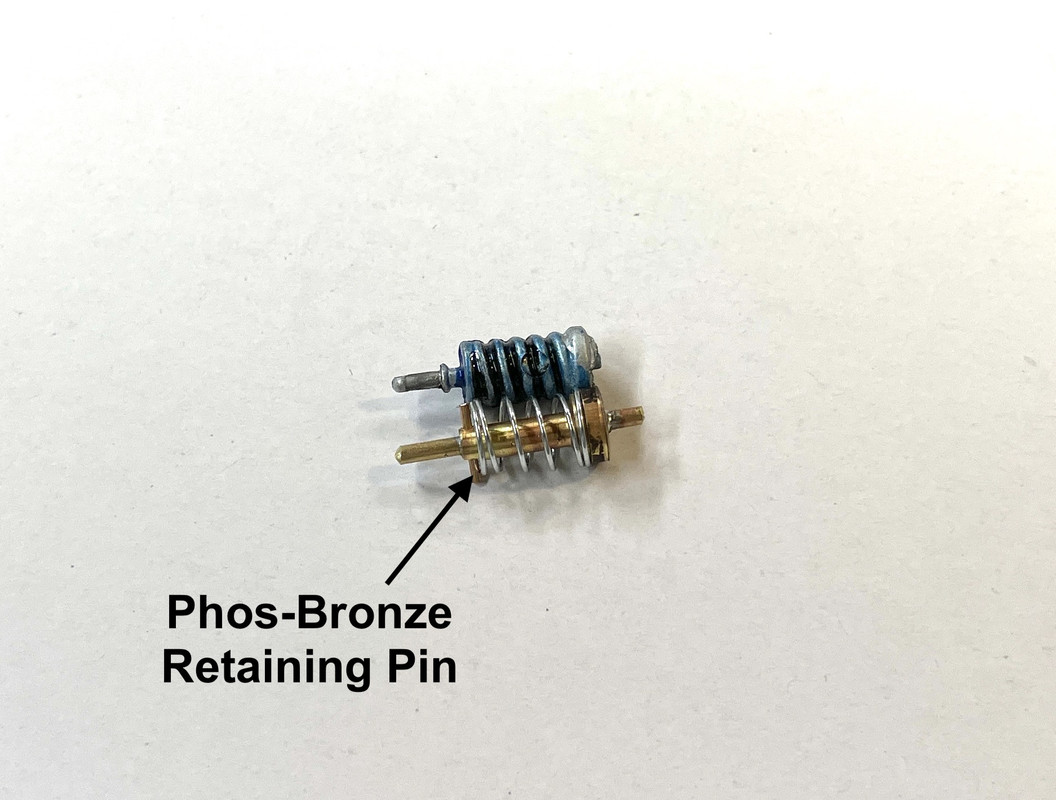
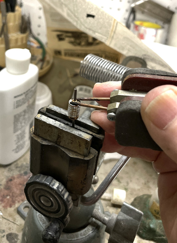
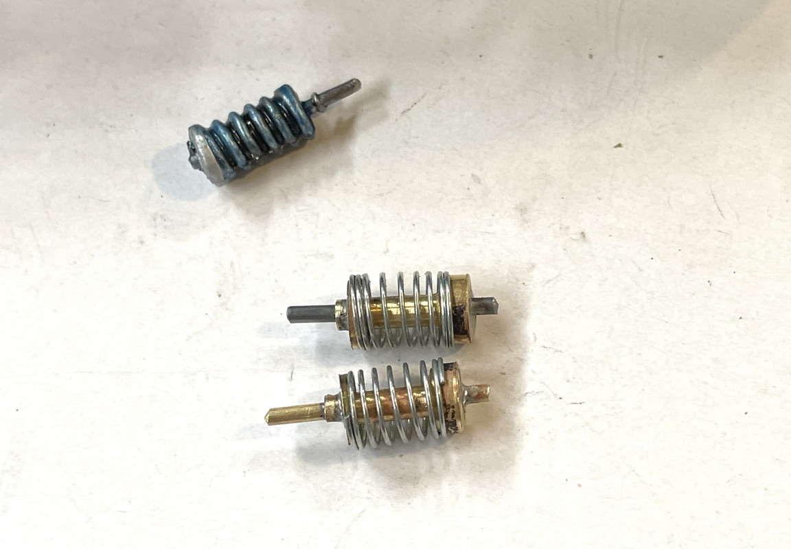
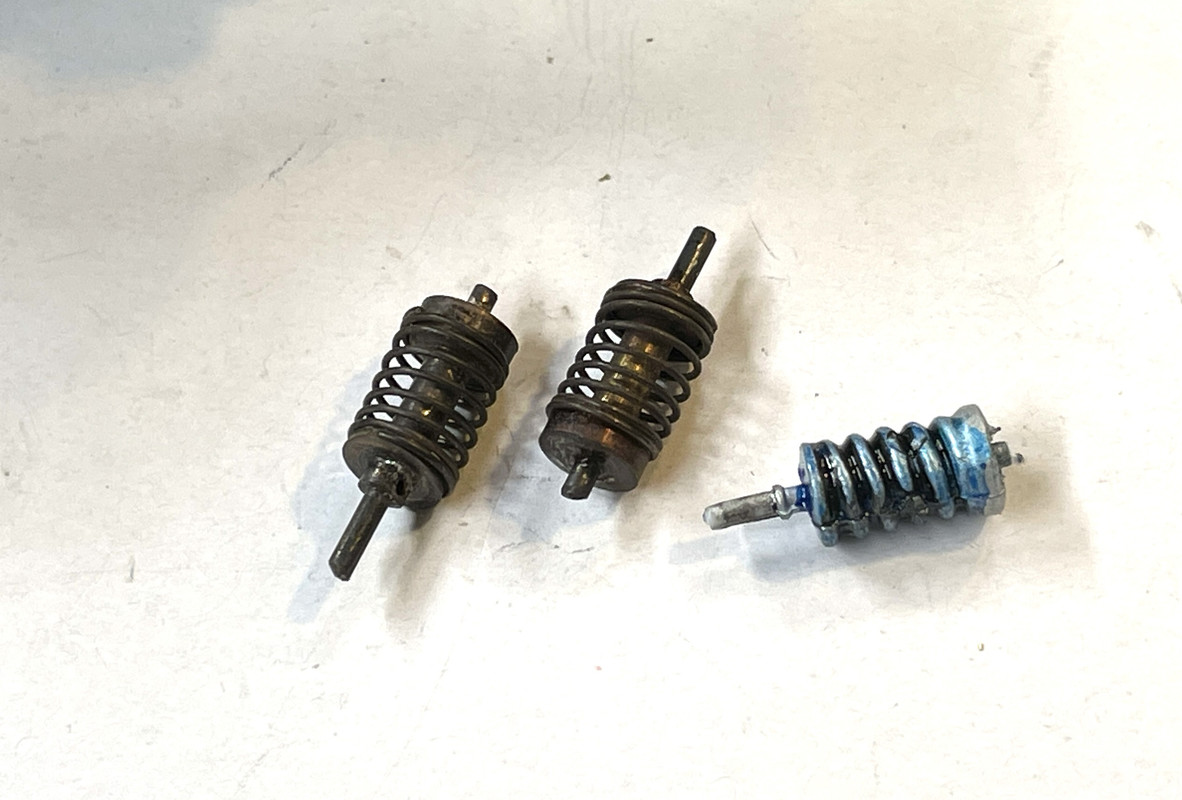
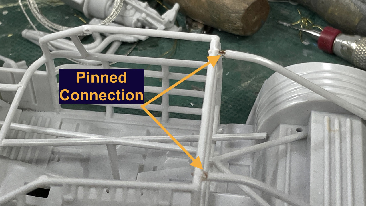
The rear angled members didn’t reach their final location properly and required drilling, pinning and CA’ing to get them to work.

So stay tuned to this short, not so complicated build. On deck will be something a bit more challenging: The Takom AH-64D Apache Long-Bow.

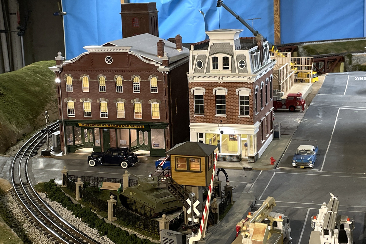
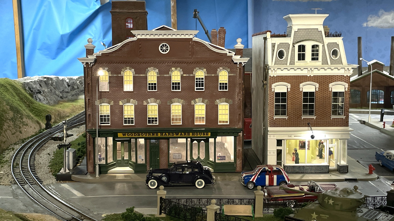
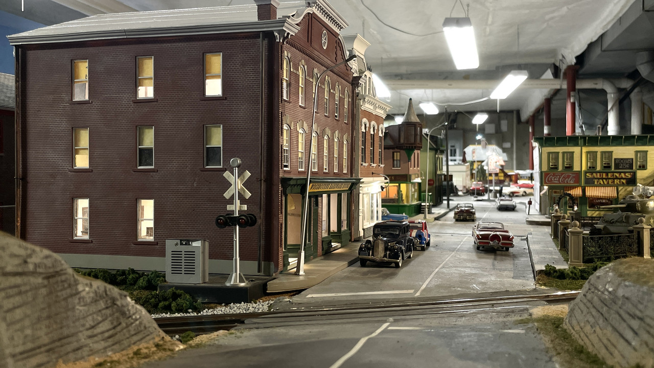
Just completed for my railroad empire is a replica of a 159-year-old hardware store that’s still functioning in Newtown, Bucks County, PA. I built it with help from the store owner and images gleaned from Google Earth. Flat surfaces are laser-cut 1/8" white acrylic cut for me by Twin Whistle Model and Sign Company. I produced all the 3D printed parts. All of this was drawn by me using SketchUp and CorelDraw.

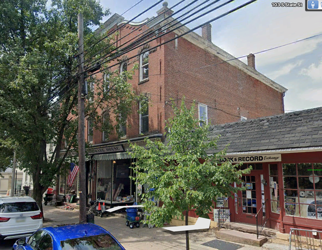
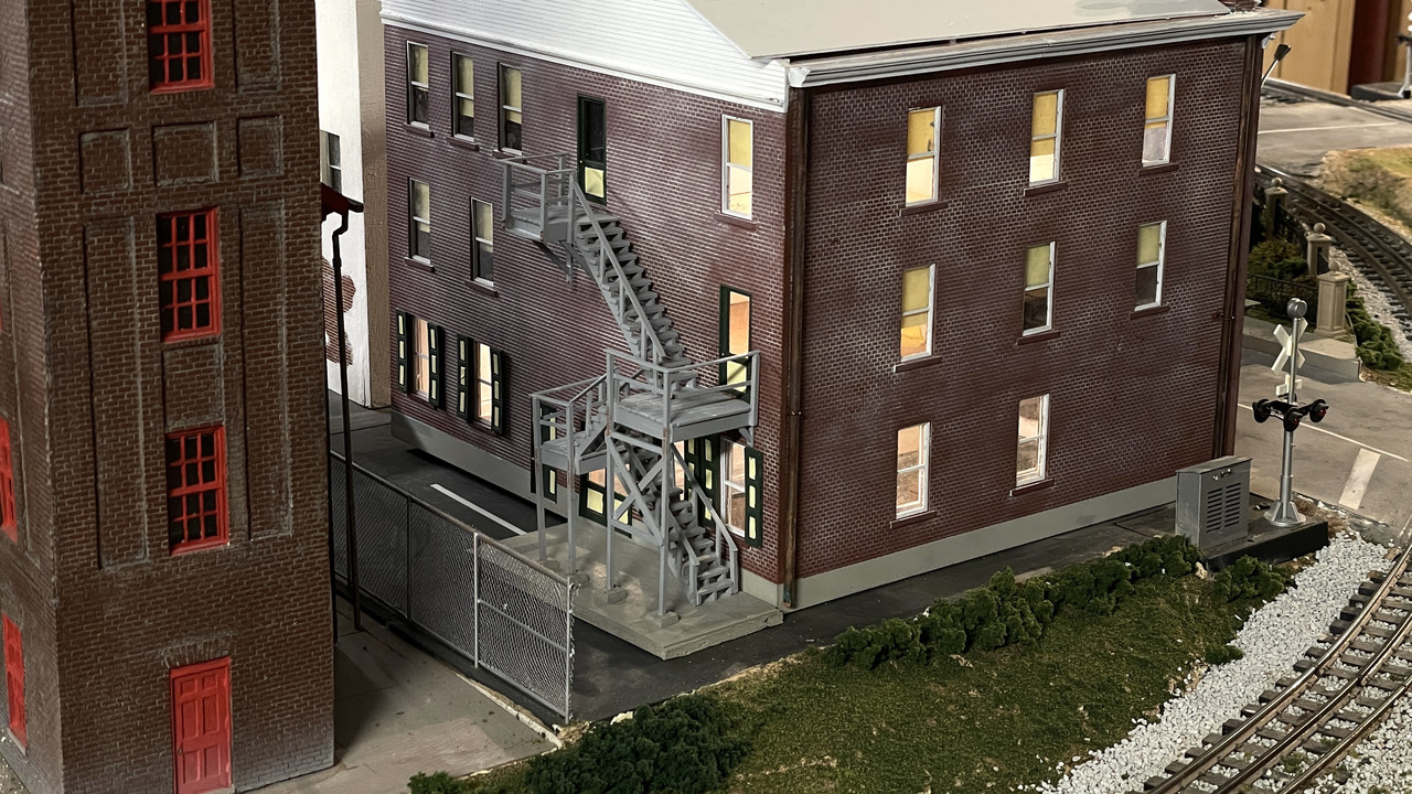
The real building has a very frail metal fire escape that would have been very difficult to model. I went with a scratch-built wooden stair.

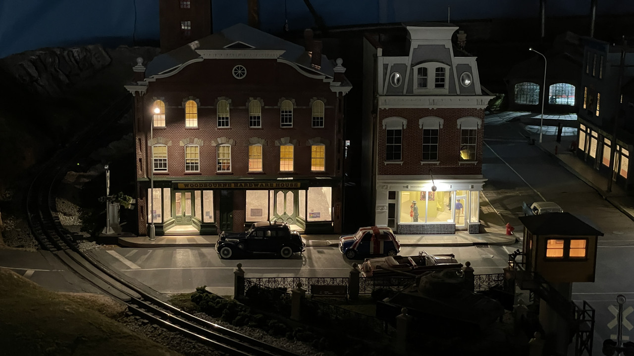
And lasly it’s all lit.

Missing is the interior detailing. I’m waiting on the owner to get me more pictures of the store on the left which is the main store. In the late 1800s, they opened up the wall and connected the two stores making a bigger hardware store.

Some of those engine details will be hidden as you get farther into the assembly. The carb is completely covered by the air cleaner.

The plg wires can be routed inboard of the headers all the way so it’s not a problem to weave them around the exhausts.

And same for the top corners of the roll cage. once the body is on, there is no way to see the top corners.

Rick

Thanks for the reassurance Rick!

Finished the roll cage, painted it and all the rest of the black chassis parts. I also cleaned up some mold lines on the body. Frankly, not having built car models very often in my later modeling years, I really don’t like the lackluster engineering especially after recently completing Meng and Tamiya products. The bar has been raised considerably and these old ERTL/AMT kits just don’t measure up.

I did one more pinning job on the rear fuel cell guard rail. Again, very little gluing area and not-so-hot mounting pins vis-a-vis their respective holes. There is a rear plate that supposedly closes off the fuel compartment from the rest of the cabin. This part had no locating indexing. The drawing showed it glued to the apex of the rear wheel wells. I did it the best as I could. There were no notches, pins, bumps, etc. to guide and hold it. It just glues on a very narrow edge to the wheel well “sheet metal”, which itself was ridged giving and almost non-existent glue surface area. I ended up filling the bumps with med CA.

Here’s another view of that rear panel and where I put it. You can see how it’s just sitting on those ridges greatly reducing gluing area. It doesn’t contact the lower surface at all, further complicating the gluing.

When I test fit the body onto the chassis, that panel really doesn’t look like it’s in the right place.

When everything was glued and set, I airbrushed gloss black over the entire chassis with only the top of the firewall piece left out because I wouldn’t be able to install the brake/gas pedal part. I tested to see if I could install the seat with all the roll cage braes in place before gluing in the last brace that went down the upper center-line. I could get the seat in so I went ahead and glued in those last bits.

Next session I will paint the gray safety net when the black is fully cured. BTW: This is Tamiya Gloss Black.

I also airbrushed all the black chassis components while they were on their sprues. I realize that this means touching up all the places where the sprue connectors were. So be it.

I substituted a piece of like-sized steel for the continuation of the steering shaft that connects to the steering box. It says to paint “steel”. What better way to simulate steel than using real steel. The two parts—real and plastic—are within 0.004" of each other with the steel being 0.059" and the plastic 0.054". As I used to say in my college R&B band when tuning up, “Close enough for Rock and Roll”.

There were some mold line misalignments at the front and rear “bumper” area. They aren’t really bumpers on Nascar racers. Reminds me of the Pixar movie, “Cars” where the protagonist’s girlfriend nicknamed him “Stickers” since he really didn’t have any headlights… Just graphics.

I was able to file and sand the front defects.

After sanding the rear area there were still some low spots which I filled with Tamiya Fine Filler and will sand out next session.

I made a test mix of the Kodak yellow. Straight Tamiya flat yellow is too yellow. Kodak seems to have a touch of red in it. I made a very small trial amount, but think it will work okay. I’m going to paint it with flat and then gloss it for the decal application. I’m not sure this is the best way to go. I could go with gloss yellow and red and be gloss from the get go. Thoughts?

Nice, I haven’t been up to the club in ages, since 2012 when I started working nights at GE.

30 years ago, my mother-in-law in Bardstown bought me a NASCAR for a gift because she knew I built models. I still haven’t touched it!

Maybe I will be an inspiration so you can build it.

Yesterday was a painting day. First up was masking the reinforcing strips on the glazing. Who would think you’d have to do glazing masking on a MODEL CAR? The ribs were in relief on the inside which I don’t know if that’s prototypically correct. I used Tamiya tape, laid the tape to the rib edges and trimmed, then added the next strip and so on.

After airrbrushing with gloss black this is the end result. There were some tiny areas that needed some hand brushing to get it right.

The rest of the session was spent detail painting the parts I had painted on Tuesday. I wish the kit had instrument decals. I dry-brushed the gauge faces. I don’t know what these gauges even look like and don’t know what the background colors are. Right now the dry-brushing was silver. Nothing was note worthy enough to photogragh. I will takes some images on the next session.

Today is an exercise day which cuts my work time short.

I hope it will inspire me. I do recall getting a set of Desert Storm decals for some driver who has long since died just to give me a reason to build it; a camouflaged race car!

Well alrighty then… here’s some more inspiration.

After looking at the prototype photos it’s clear that there was no seam between the rear (bumper) and the body which is how the front is. Therefore; I had to apply filler to both sides after sanding down the obvious height differences between the separate bumper part and body. I will sand out next session.

Lft side:

Rt. Side:

I then spent the rest of the session detail painting all the little bits. I’m so used to the new massive models by Meng, Takom, etc., that the simplicity of this one is almost boring. I used to churn out a model a week in my early teens since most of them were just like this one. And I’m doing it almost totally out-of-the-box, so I’m not fussing with superdetailing, PE or scratch-building. When I built my replica of my '66 Fairlane GTA I did spend a lot more time opening the door, detailing the engine including turning my own vacuum advanced for the carb, and making scale hood hinges. The hinges were drawn directly over pictures of real '66 Fairlane hinges found on eBay.

By their nature, NASCAR autos are much simpler beasts. They don’t seem to have hood hinges, fender walls in front, AC or power brake cylinders, etc., so no matter what, they are simpler to build. Oh… and they don’t have any doors at all.

After detail painting the engine I fit in in the chassis for this image. Note the shiny “chrome” lower part of the oil filter. I used decanted Molotow Chrome ink to give a very nice chrome finish by brush. Carb color is base Tamiya Flat Aluminum overcoated with Tamiya Clear Yellow. Belts and pulleys could be defined better…

Here are the rest of the parts: The coil springs would have been nice in real springs. The call out is steel blue. I painted aluminum with Tamiya Clear Blue overcoat.

After painting fins aluminum I used Tamiya Black Panel Accent to fill in all the slats. I did the same with the oil cooler that’s slung on the frame in front of the front left wheel, and the spaces in the faux coil springs.

The crappy instrument panel is the best I could get it with the gauge faces glossy and the surrounding panel flat to differentiate the two. I like painting instrument panels, but I like them to give you more to start with. This is under pretty heavy magnification. Looks better to the naked eye.

I still have to finish that rear bumper and then paint the body. Then assesmbly will begin in earnest. A model in less than three weeks. Unbelievable. Compare that to 11 months for the Iowa Turret.

While sanding and polishing the filled rear bumper joint, one of them broke loose. The gluing surface was very thin. I reinforced the re-glued area with CA, and added more filler. When set, I re-sanded the area and worked it glass smooth with a series of polishing abrasive clothes starting at 3200 grit and going to 8000. As an afterthought I realized that I should have reinforced the joint from behind with some strip styrene. Oh well…

I then airbrushed semi-gloss black for the entire interior. To facilitate this, I taped the rear deck and hood in place from the outside.

When dry, I reversed the masking and masked all the interior openings including fastening the rear deck and hood from the inside. This was to keep any exterior color from fouling the newly painted insides. The instructions didn’t call out any interior color, but looking closely at the box photos, you could see that the insides were black.

I built the holder when I painted the Fairlane and kept it. Making your own tools is a good use of time.

I don’t spray solvent-based paints inside, and the weather was perfect for doing it outside. My “spray booth” is the top of our trash containers. There was a slight breeze and I always do a wind check to make sure I don’t spray myself. I used Tamiya Fine White Primer. White is the necessary base color when you’re going to shoot yellow.

The blue is skylight reflecting on the white. Trust me… it’s all white.

The rear bumper blending worked out reasonably well. This will dry over the weekend and I’ll start finish painting next week.

While the body was drying I got the ignition wiring installed. I took the suggestion to just run them all under the exhaust headers. This worked. I painted the brass wires a more appropriate color. I don’t know where to run the coil line since one is not evident in the model. There is also a ton more piping on the actual engine than the model shows. I’m not going to worry about it. Many of the NASCAR engine pics online are of new engines, not as they were in the 1980s.

I also don’t know what weathering (if any) to do with the white headers. Like most multi-million dollar race machines. Engines and systems are changed regularly and do not age like normal mortals do. Drag engines are torn down and rebuilt every 30 seconds or so. NASCAR engines are probably pulled and replaced at the end of each race. That would probably include exhaust components also. I may be wrong here since I do not follow NASCAR regularly.

Next up is doing something with the fuel lines. These are braided. I bought some properly scaled braided line, but balked at the cost of the tiny metal fittings. I’m going to design and 3D print some fittings. Unfortunately, that must wait until I get my printer running again. The mother board/LCD input panel failed suddenly. Elegoo was nice enough to ship me new parts for no charge, even though I was out of warrantly for three months. It’s a Chinese company, but in my four-years experience with them I find them to make a good product and have very nice customer service. The new parts arrived yesterday and I will install them on Monday.

I also don’t have a clue about the throttle linkage and will do some research on the topic.

What is the best clear coat that’s also able to be rubbed out to high polish?

All the DADs out there; Have a happy and fun Father’s Day.

On Monday, I was able to spray the first coat of the “Kodak” yellow. Before spraying, I went over the primer with some 4000 grit wet or dry abrasive. I then mixed up some “Kodak” yellow which is Tamiya Flat Yellow with drops of Tamiya Flat Red until it got a little warmer and fuller, but not orange.

Today I again went over it with some 4000 grit, but even with a very light touch, sanded off paint on the high spots. The paint was a little thin elsewhere anyway so I re-coated the model. Tomorrow I’ll try again using even finer grit like 8000 to smooth it out and then shoot it with some clear or another. I have some AlClad water-based clear that’s pretty good and it can be rubbed out.

Meanwhile, I fixed my Elegoo Mars 3, 3D printer with a new motherboard and touch pad. So I’m going to design and print the plumbing fittings for the engine bay. I’m using 0.020" braid and need the end fittings for it. This will be used for oil and fuel lines. I’m drawing the parts in SketchUp scaled up 1,000X so SU doesn’t have trouble with the segment sizes, and then I’ll shrink them .001 and create the print files. I’ll let you see what I’m doing. To use Accurate Details metal fittings would have cost way too much money for this simple, non-award winning, project.

Very little building today. After a very light sanding with 6000 grit, I shot the model with AlClad Aqua Clear. This water-based gloss coat requires a good 6 hours cure time before doing anything else with it. I have used it before and it can be polished. Tomorrow I will do a sanding and then shoot it again.

Meanwhile, with the 3D printer fixed I’m designing my own engine plumbing and will print them. I’m also going to attempt to draw and print a good looking Holley Dominator carburetor to replace the pathetic one that came with the kit. While I’m at it, I’ll inlcude it with the riser block that traditional with NASCAR engines.

A NASCAR car resembles a normal car with about same comparison as one of my pencil sketches resembling the Mona Lisa. They are a roll cage with four wheels and a powerful engine. There is absolutely nothing that is actually a Ford, Chevy, etc.

With the clear coat’s show curing time I covered it with a box so environmental dust doesn’t get imbedded.

With my 3D fully functioning again, I was able to make some customer plumbing fittings and a big ass Holley Dominator Carb that looks a whole more like it means business that the pitifully undersized one including in the kit.

While the carb seems really large, I was able to download images of the carb from Holley’s website and the bolt pattern. From the dimensions on the bolt pattern I was able to scale the entire unit. This is how it looked in SketchUp where I drew the carburetor. It’s just a big carb.

Here’s the complete drawing in SketchUp. It’s not a perfect replica, nor did it have to be. Besides simply being so small AND being partially hidden by the air cleaner, the level of accuracy was sufficient. I also took the liberty of adding the fuel manifold with a pipe fitting on the end for the braided tubing to reduce the level of fussy scratch-building I would have to do.

I got the 2nd coat of Alclad Aqua Gloss after a light sanding with 4000 grit.

After polishing the 2nd coat with 6000, 8000 and 12000 grit plus Novus Plastic Polish I’m declaring it shiny enough for a race car.

After pulling off all the masking I found that I made a booboo. I SHOULD NOT have painted the hood and trunk lids attached to the body since it hid areas that needed to be body color. This was evident on the hood and trunk edges and more importantly, on the panel that covered over the radiator.

Futhermore; the masking on the spoiler covered part of the body in the back corners.

I touched these area by hand. Remember, my base color is a mixture of Tamiya Flats so the area in the rear is going to need some gloss. Annoying!

I also printed the plumbing fittings. Here are the carbs and fittings set up together on the machine. A reminder: Unlike a string (FDM) printer where the amount of material on the building surface affects the print time, here you can load the plate up since it prints everything in one complete layer at a time. What directly affects time is the height of the part, the thickness of each layer, which in this case was 30 mircons, and the exposure time for each layer.

I always print many more parts than I need. There are ALWAYS failures.

My first attempt on the pipe fittings was successful, but they were just too small to handle and get the braided tubing into. I redrew enlarging the opening a tad and the over size about 130%. This printed by failed.

Reason: I drew these supports in SU and made them just a bit to fine. The supports failed to hold the parts intact as each layer was lifted to bring in fresh resin for the next one.

Back to the drawing board. I added more meat to the supports and will print again on Monday.

The carbs did print successfully. I trimmed one and post-hardened the whole batch. Of course the glue joint holding the original kit carb on the intake manifold was unbreakable. I had to resort to some pretty hefty flush cutters to cut it off. I had to sand its remains off the manifold and then glue the resin one in place with medium CA.

Notice there is throttle linkage which I can hook up to the rest of the car if I so decide.

Other view showing fuel manifold.

Onward and upward. See y’all on Monday. Have a nice weekend.

Happy Monday.

I changed out the LCD print screen protector on my Elegoo Mars 3 3D printer. The factory standard one was a piece of some kind of film that got scratched in several places. I thought it was tempered glass and was wondering how it got scratched so easily. Instead, being film,e it scratched when I wanted to scrape off some hardened resin. The new protector is tempered glass and should hold up well. The packet came with 3 so I have replacements.

I was then able to print the redesigned plumbing parts successfully.

Before getting down to that work, I had to paint one more thing on the body… the black panel on the mid-door pillar. I masked the heck out of it so no black got on any yellow.

I airbrusded the gloss black and then demasked. Not great, but should work. There’s an “Olds” decal that goes on this pillar.

My strengthened supports enabled the plumbing parts to form properly. That said, they’re really, really little, and the getting the braided hose into them is almost an exercise in futility.

I’m using 0.022" phos bronze to provide the connections between the fitting and the engine. I had to drill the tiny openings on the fittings slightly larger and deeper. This is painstaking and a little frustrating work. I am persistent to a fault.

First was putting the fittings on the separate oil pump and the crankcase oil sump. At first I attempted to put the fitting on the metal and then fit this into the holes in the engine. Wasn’t so hot. I then reverted to puttting the metal pins into the block and gluing (med CA) the fitting to these little metal stubs. Worked better… not great… just better.

I got the all installed. Notice that the exhaust manifold on that side is off the engine. It was blocking working on the pump. But that’s not why it broke. Seems that attempting to fit the engine into the chassis with the pipes on AND the firewall in place put a lot of stress on the headers and one broke loose… the oil pump… which was fortuitous since I needed that one off anyway to do this piping work. I was fitting the engine to check the air cleaner clearance. I had to put some packing under the cleaner so it would sit firmly on the new and much larger carb. It fits, but the hood probably will not fit right. I’m going to display with the hood off, so no harm no foul.

And then it was time to try and get the braided piping into place. Took a while to get this first one. The plumbing fixture’s holes are very deep and the braiding just barely enters. Lots of CA!s

Now that I look at it, I realize that I didn’t install the compression fitting on the braid end. I’ll pull it off next session and get it right. It’s the first time I’ve ever used miniature braided piping and it’s not easy especially at the 0.020" size.

I use a mix of 80% Elegoo ABS-Like standard resin and 20% Siraya Tenacious flexible resin n to toughen up the finished part. It’s really important. These little elbows are quite tough and I didn’t break any of them in their narrow part even though I was treating them a bit roughly.

The braided lines are almost done. I’m not overjoyed! The coupling fittings I printed, while really scale, are too small to use effectively. I’m printing more today that are 30%, 33% and 36% larger to see if I can work with them better. I don’t think I’m going to redo the lines that are done, but I have more to do with the cooling lines and the oil lines to and from the oil filter and oil cooler. Regardless of how good something looks, if you can’t get the braided line into the fitting or the thing disintegrates when you try and open up the holes a bit wider while attempting to hold in a tweezers, they really don’t work at all.

Here’s the fuel side with the line running from the fuel pump to the fuel rail next to the carb. The stock fuel pump is not prototypical for a NASCAR engine, but I didn’t have any good references to replace it. I designed the fuel rail fitting to be oversize so I wouldn’t have to wrestle with the braid insertion. While a bit big, it went together easily.

Closeups don’t do the model justice. Looks better to the eye…

The oil side works, but the line runs are too chaotic. With not being able to insert the braid INTO the fitting, only just butt-glued to the end, I really can’t manipulate them. As it is they kept popping off and are very, very unstable.

Another view with the air cleaner sitting in the final position. I have more work to do on the aircleaner. I drilled the oil filter for the in and out lines. I also don’t really know how the line goes in and out of the oil cooler.

At a distance, the engine will look busy, which afterall is the reason we put all this stuff there in the first place.

While manhandling the chassis to get the engine installed and drilling the hole in the firewall for the oil line to run to the oil tank in the car’s rear, I broke the upper roll cage cross-brace. This required pinning and gluing with CA to make it secure. It is not visible when the car body is in place since it’s up at the roof top.

The new fittings work. They beefier and enabled me to drill them without falling apart. I printed them with the through hole, but it still needed some elargement. That said, they’re way oversized. They look like they’re better for a 1/16th scale model, not 1/24. But the scale sized fittings are simply too small to manipulate and get the braiding inserted. I’m going with bigger. It’s mostly hidden and adds interest.

It’s much sturdier than the previous versions I was messing with.

The piping continued breaking and I decided to replace them with the larger versions. In order to get this image, I installed the engine without both headers. I’ll get them in later. The piping just fit into the frame rails.

I also attempted to build a rundimetary throttle linkage that will go down along the firewall and disappear below. Again, not scale nore accurate, but busy. Air clearner is now on the model. 0.022" rod, while small in your fingers, is actually a little to robust. 0.012" guitar string would be better, but I didn’t feel like fussing with it.

Started decaling today. With the age of this kit… instruction sheet had yellowed… I picked one that didn’t matter too much about its integrity. As I expected, it started to fall apart. I then coated the rest of the sheet with clear gloss. If that doesn’t work, I have a fall back position. I scanned the sheet and will make my own decals should the coating not do the trick. Some of the decals have white details included in them. For those I will have to print on white-backed film and then razor cut around the perimeters so all the rest of the white paper is not included in the final decal.

This looked a bit rough, but after I put some micro-sol on it and it fully dried, it settled down pretty well. There are at least five tears in this decal.

With the decaling having to wait for another day, I got back to work on assembly. I gave up on using the oversized plumbing fittings on connecting the oil filter. There were too big to nest against one another and interfered with getting the engine in place.

I rehooked up the exhaust headers. It was a distinct pain to do it. They’re not set very tightly against their mounting surface, but nothing should disturb them.

I decided it was time to get the rest of the interior in. This included the funky shift lever, seat, blower behind the seat and the fire extinguisher. I had to do some internal surgery on the boot under the shift lever so it would center properly over the faux shift mechanism.

I moved rearward toward all the rear suspension parts. The first was this stub-frame that had very poor locating information. It calls for it to be painted blue. That surprised me since the rest of the chassis is black. I followed the instructions and painted it blue. This member basically supports the rear shock absorbers.

I got the remainder of the rear in. This was not easy either. I tended to rush the assembly and was doing things before the previously glued parts had set sufficiently. They broke loose a couple of times. I’ve said it before, “I am not patient! I am very persistent.” My lack of patience is primarily how I screw up by rushing paint or glue drying. At my age, I’m still a pretty good model builder. As a kid, I was a terror. I’d crank them out like an assembly line.

I sort of screwed up where the rear brake discs were going to connect to the rear axle. What were half-moon connectors I assumed were mismatched molds and mostly removed them. The discs are buried in the inner wheel hubs, so I may or may not include them depending on my luck installing them. I also found that I’d lost the metal axles. No proplem. Turns out it’s a convenient 1/16" and I had some mild steel rod of that diameter. Made it a little long and then measured the end play with the hubs attached, and trimmed to length. I have one of the more inexpensive Mirco-Mark mini-powered miter boxes. I have an abrasive cutoff wheel in the it and it makes quick work of cutting rods and tubing perfectly square and clean.

Pinned another one of the roll cage rod ends. The tiny plasitc pins and small glue area just weren’t holding up to the handling. Pinning with 0.022" rod does the trick and makes the joinery much more survivable to my rugged handling.

Hi, Builder -

Very nice work on the car, it’ll be a dandy when finished. But for me the real star of your post is the hardware store and fire escape. A beautiful job, I spent a good while enjoying seeing all of the details you incorporated, what a perfect addition to your setup.

Thanks for the great photos and details.

Patrick

Happy 4th. Everyone be safe and don’t lose any body parts with fireworks. We model builders need all of our body parts intact.

I hate to agree with you, but the hardware store was a much more challenging, and thus rewarding, endeavor. I’m kind of grunting through the car model. Frankly, I’m spoiled. Between the sophistication of the modern kits, and the intellectual challenge of the scratch-builds, a 1980s car kit just doesn’t excite me that much any longer. That said, I never leave things unfinished and I will finish this also.

The day started with wanting to try the decals again with the laquer coating. I chose to put on the big “Kodak” on the hood, only to find that somehow, I got gloss black paint on to the final finish. Instead of attempting to remove it with solvents and destroying the underlying finish, I used Novus Plastic Polish and a lot of elbow grease and rubbed it out while mostly preserving the finish. The big decal was going to cover a lot of area so it could hide any other blemished.

Once again, the decal started splitting apart, and to make matters worse, the laquer was washing off the decal in a white film. I perservered and got the pieces to fit together.

coating the decals again with Micro-Sol Decal Coating Liquid to try and prevent the breakup that I’m experiencing. I coated with Micro-Set and let it dry. The results ain’t so hot, but they may be okay after another gloss sealing coat. I don’t about you, but it makes me very unhappy to have a finish ruined by decals after spending a coupld of days laying it down.

Here’s the decal mostly cured at the session’s end.

I looked into the possibility of substituting rear springs for the plastic ones, but that ship has left the dock. I did have springs of the correct diameter in a collection of springs I bought a few years ago from Amazon, but should have thought of this earlier. In another forum a reader wondered why I hadn’t changed out the springs. I hadn’t even thought of it.

To try and forestall further decal disintegration, I coated the sheet with some MicroSol Decal Coating Liquid. While this was curing I started working on the wheels. They have a terrible mold line right done the center of the tire. I cut off what I could with a #11 and then used my MicroMark power hand sander and other abrasives to make the tires look more like tires.

I also attempted to paint the “Goodyear” logo on tires since the car’s photos clearly showed white lettering. It’s passable, but not great.

I also got the radiator installed with the hose painted with Molotow decanted chrome. If you repeatedly depress the nib end of the Molotow pen, eventually a big blob will leak out and you can use it with a brush. It can also complete destroy a model if that blob comes out when you’re using it as a pen. I know this because, Brian Bunger, the owner of Scale Reproductions, Inc. (one of the best hobby shops in the USA) did this on a beautiful 58’ Chevy Impala model when painting the trim.

And then while attempts to assemble one of the wheels with the inner and outer halves, I dropped an inner rear wheel and its disc brake. The disc brake was sitting on the floor directly below my feet, but the wheel was no where! I mean NOWHERE!!! I crawled around on the cellar floor, expanded the search area, explored places where “It couldn’t possibly had gone”, and found nothing. I know round things can roll, but come on man, it should still be in the room… right?

I searched for a good 10 minutes. The part is no longer in this dimension. That’s the only possibl e explanation. In fact, I actually didn’t hear it land. Small parts can reach relativistic velocities and they’re falling and transit to the other dimension before hitting the floor. Go ahead. Prove me wrong!

So… in desparatiion, and always having a way out most jams, I’m in the process of turning a new one out of aluminum. Luckily, the inner wheel is just a plain cylindrical shape, unlike the outer half with the spokes, compound curves, lugnuts, etc.

This is like the one that diappeared.

And here’s the stock being prepared in my miniature, 40 year-old Taig Lathe. The lathe is a godsend and has gotten me out of a lot of jams, too many to count. It’s capacity isn’t much, but within that envelope it can work wonders.

I chucked the aluminum in a 4-jaw independent chuck because the stock had a large overhang (I hacksawed off the excess) and I needed a very secure clamping. The Taig 3-jaw self-centering chuck has aluminum jaws and can’t really tighten as much as I needed here. I used a dial indicator to true up the mount before turning. I can usually work within a couple of thousandths precision with the machine.

I may have more time in the shop today and I will post the rest of this small machining project.

Hope everyone had a nice 4th. Ours was subdued since the grandsons are not around much any longer. The older one, is working in Chicago at Medline as a systems engineer and the younger was spent the weekend at French Lick, IN, with old HS friends. We knew that this would happen as the kids grew up and we’re really happy that we moved here when they were little guys. It went very, very fast.

The decal settled in as good as can be expected. I will see how well the rest work with the MicroSol sealing coat. With a leveling gloss coat, they’ll be a bit more presentable.

I got down to business on machining that “missing” wheel. It took three tries. The first approach, to do all the o.d. work, reverse the piece in a 3-jaw chuck and then treapan (cutting straight into the end of a revolving workpiece), didn’t work. The machine is chattering a lot and the wall thickness of the diameter was very narrow and it failed during the operation.

This was after the facing operation and before I attempt to trepan the bore. You can see the small lip that’s preventing the piece from sliding backwards in the chuck.

My second attempt didn’t even get started.

The third attempt, I reversed the workflow, doing all the boring ops first, then turning the o.d. and finally cutting off to length. This worked. It provided enough stock to absord the cutting forces. Trepanning is a tough operation since you’re plunge cutting which is a big load on the tool. It chattered like crazy, but this was an internal surface that won’t be seen. I also drilled the 1/16" hole for the axle.

I had to regrind my little boring bars to enable them to clear the i.d.o of the drum and the o.d of the center hub. You can’t just own a lathe. You need a bench grinder too. My grinder is a Dayton machine that I bought in 1972 when I was teaching shop and fixing lawnmowers out of my garage. Good tools last a long time.

The new wheel fits the tire perfectly! And then, I found the missing wheel! I knew that was going to happen. It was in the darn tire!!! When I dropped the disc brake, I assumed that the wheel dropped too. I checked everywhere, except inside the tire itself. Reason: the tires had a black rubber center that needed to be cut out. When viewing the tire from the open end, they were black on the bottom. When viewing this tire with the wheel still inside, it too was black in the bottom. Ergo, I missed it. So I spend almost 3 hours creating an unneeded workable part. It was a fun machining practice.

Up next, more decal fun and building up the front suspension.

I painted myself into a corner by assembling the full rear end without the driveshaft installed. In my attempt to get it in, I popped loose most of the glue joints including the ones holding the rear coil springs in place. This presented an opportunity. I’m going to make “real” springs. The quotes are because, while the springs themselves will be real, the mountings will not permit them to flex, nor does any of the other suspension components have the abilty to move. It will just look much better.

I also got all the tires and wheels assembled and the tires painted. After a bunch of fussing the tire paint is okay. Not great… just okay.

I’m going to turn the spring mounts out of brass and have visualized how I was going to go about it. The springs have to be compressed to the correct size and held that way without putting any pressure on the fragile plastic parts. To do this I will machine the main body with the mounting pins on each end and one flange that holds one end of the spring. I’ll then machine a round plate with a hole in it that will compress the spring. I will solder this in place at the correct distance. That’s the biggest challenge… holding it compressed while I do the soldering. I’ll figure it out. I’ll use the resistance soldering unit that will help me clamp and solder at the same time. Stay tuned…

Really got into the spring making today. Instead of machining the 1/16" pins on both ends of the spring assembly, I decided to use a piece of 1/16" rod soldered into the spindle. Now, I realize that the scale springs DO NOT have a central column, but are supported by both ends fastened into the car’s frame and rear axle. I didn’t want a working spring since the force would rip apart the fragile construction. I machined a spindle with one end having the larger retaining flange (as per the plastic version). Then drilled it slightly oversized than 1/16" (#51 drill) since I was going to solder it in and didn’t need a tight fit.

This image shows the spindle after soldering with the Resistance Soldering Unit (RSU). I machined a small lip on the flange to help center the spring.

To retain the spring I first tried it with a phos-bronze retaining pin in a cross-drilled hole. I filed a small flat on the spindle and then drilled with a 0.033" carbide drill. It was very careful, slow going work. When the drill grabbed just as it was exiting, which often happens when drilling brass, it broke. I was able to extract the broken drill and the hole worked.

For the carbide drilling reason AND the tendency for the spring to work itself around the pin, I decided to go with Plan B. Plan B was to make small retaining plates drilled for the spindle diameter and again using the cross-drilled, but this seemed like overkill. I then went with Plan C using the end plate and then soldered in place, again with the RSU. As I noted in yesterday’s post the RSU has the ability to hold something while soldering and I used that feature to full advantage here.

I compressed the spring while maintaining electrical contact with both the plate and spindle. Solder ALWAYS flows to the heat. By heating both surfaces with the current flow, the solder joined both pieces quickly and with strength. The power is applied by a foot pedal. You heat and solder, but don’t let go of the tweezers until the joint cools and is stable.

Here are the two rear springs completed compared to the kit’s plastic part.

Their diameter is slightly wider than the plastic version, but that’s okay since these were the springs I had. I could have wound my own, but that would be making this an even more intense project. When installed, as you’ll see, the effect is fine.

I chemically treated the finished parts with Jax Brass Darkening Solution. It’s pretty dark. I can still paint them if that’s necessary. I’ll leave it up to you guys… paint or not paint?

I had to open the holes in the model to accept the slightly larger diameter mounting posts. I installed them for this image, but did not glue them in (CA of course gluing metal to plastic). I like the look.

With the central column they look like a strut with the spring wrapped around the shock absorber. Speaking of shocks. I have to scratch build one of those to since one of them got whacked when I was attempting to get the drive shaft in.

Next up will be the front springs. Now that I have the machining and assemnbly routine figured out, making them should go quickly. The front springs are a smaller diameter than the rears, and I have springs of a smaller diameter will work.