Machined and built the front springs. They are shorter and narrower than the rears. I used a smaller spring diameter and had to cut the length in half with a hard-wire cutter. Again I changed the scheme. Instead of machining the inner sleeve, I just machined the ends and used the steel shaft to both establish the length and serve as the mounting lugs. I drilled the stock first, then turned the .117" centering land and then the .160" o.d. I moved the cutoff tool over and cutoff the piece. After the first two, I added a twist (no pun intended) by letting the drill remain in the cut so when the work piece parted from the stock, it didn’t go into the ether. This worked elegantly.
I cut the land almost by eye so the spring just slid over it without much play.
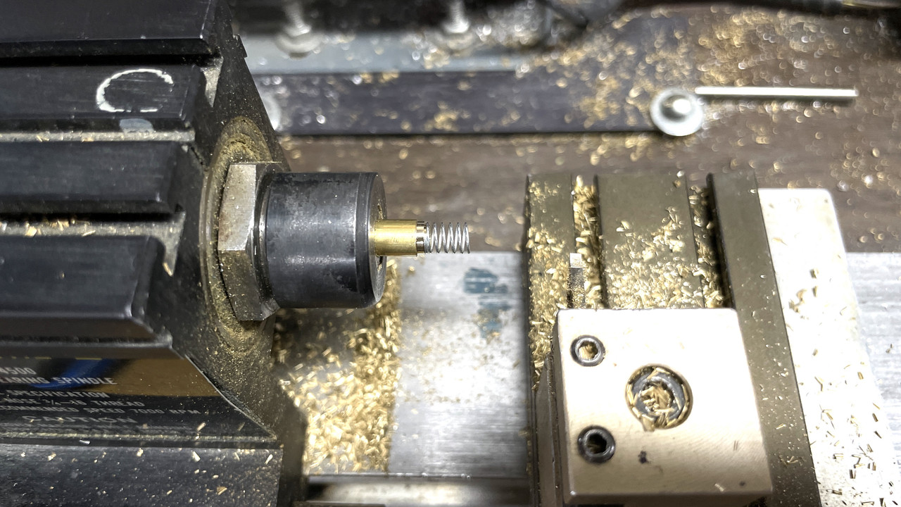
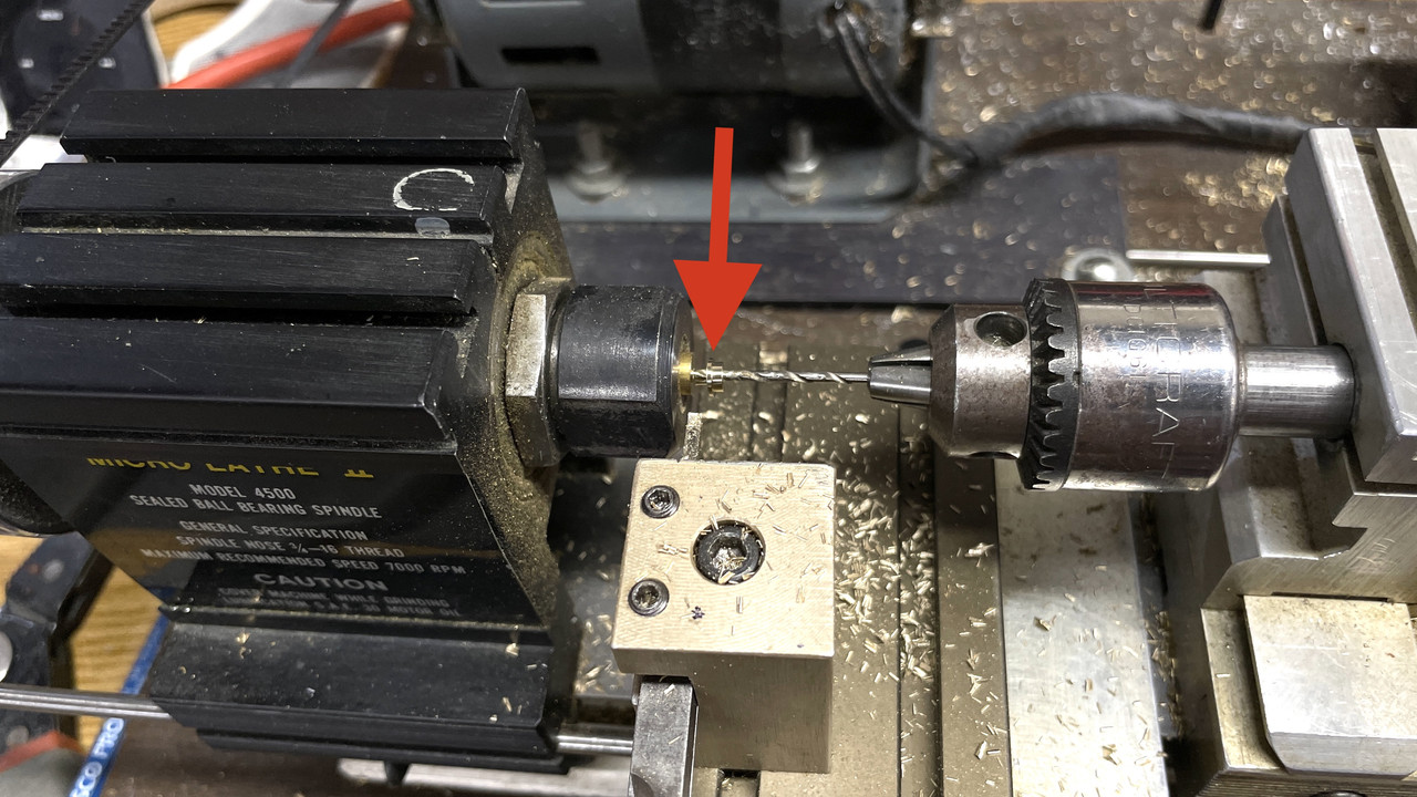
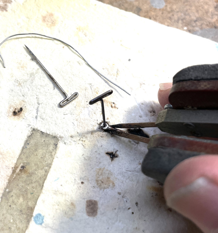
Here is the cutoff operation with the drill supporting cutoff workpiece keeping it under control.
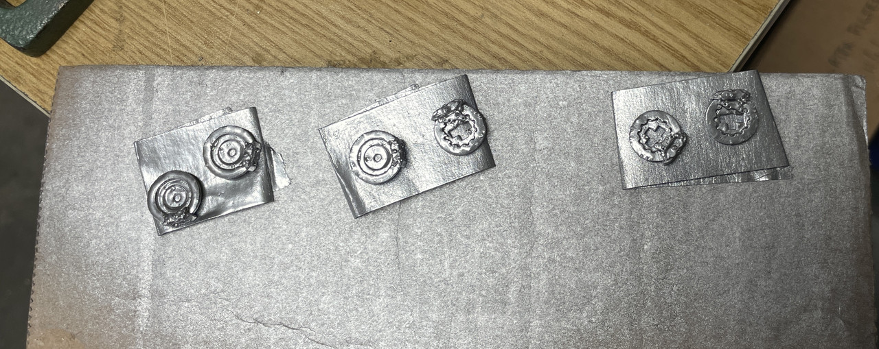
I soldered on end onto the steel center rod, placed the spring and then soldered on the other end. I held the center rod in my PanaVise, and applied enough pressure with the RSU tweezers to set the spring compressed length. While holding it at this point, I soldered on the other end plate. This worked nicely and was simpler than yesterday’s method on the rear springs.
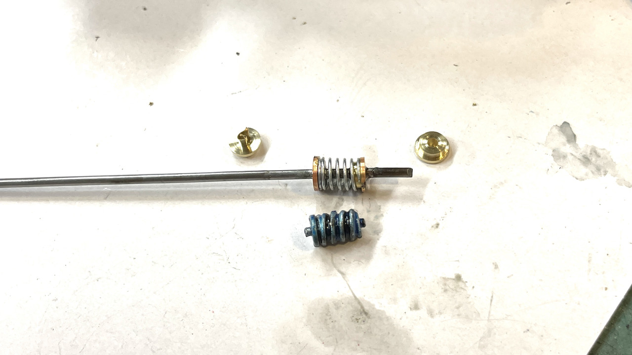
Afer soldering I clipped off the excess center rod with some beefier flush cutters.
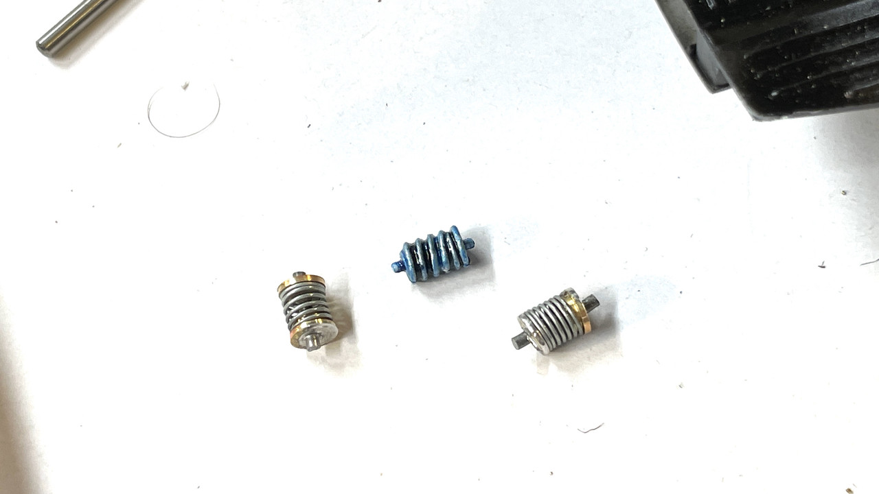
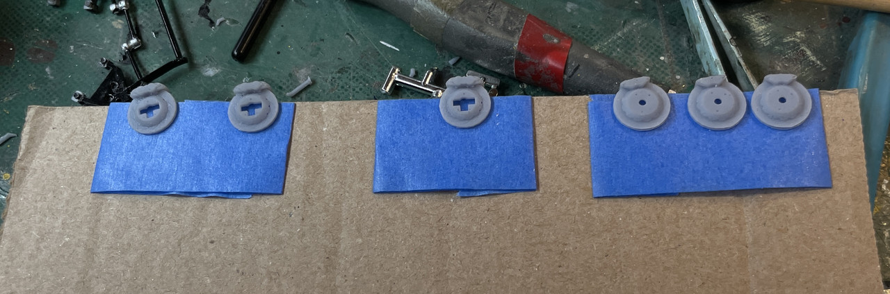
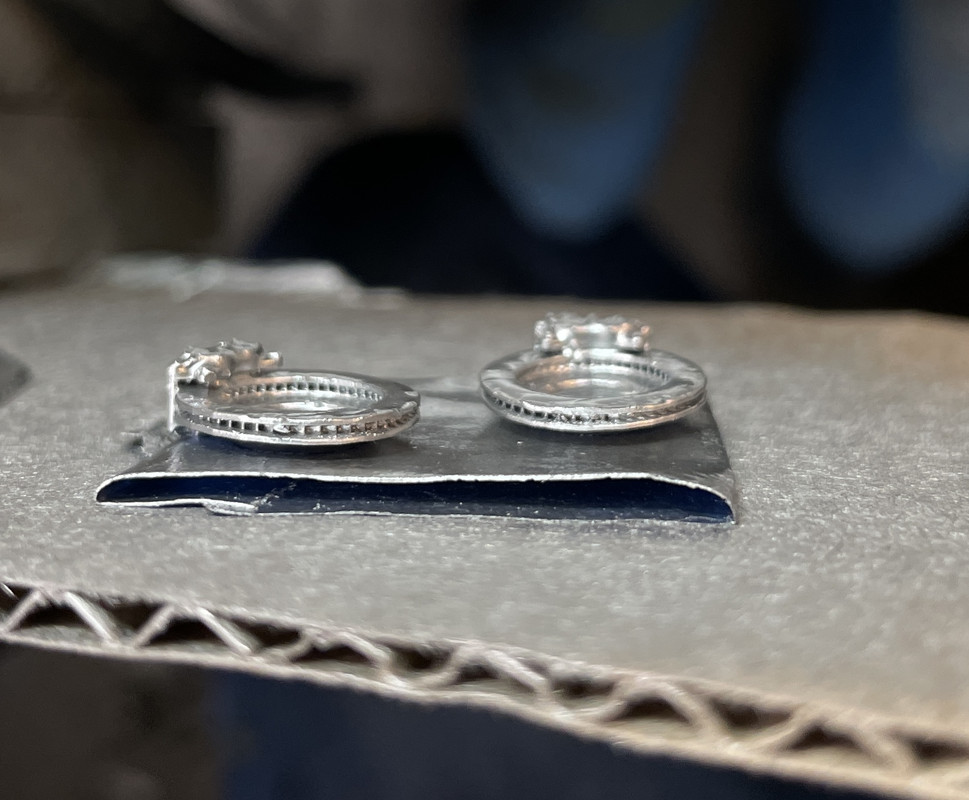
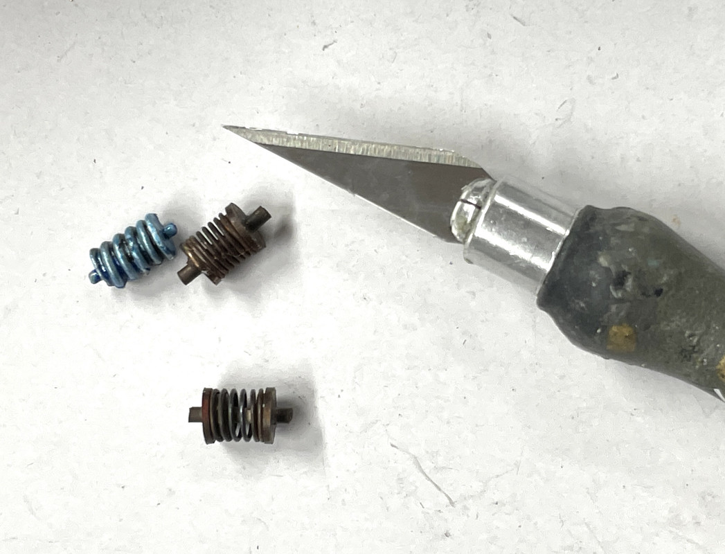
They compare reasonablly well to the kit parts. My springs have more turns, but I don’t care. Chemically treated these like I did the rears.
With the machining jobs done I turned my attention to remaking that broken shock. This little job took more time than the front springs. It wasn’t hard conceptually. It was hard because I kept breaking solder joints or losing tiny parts and had to make stuff over.
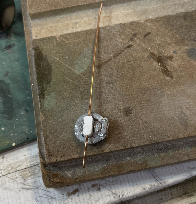
The scheme was cut a piece of brass tubing on the power mini-miter saw as the end lug and solder that to a piece of properly sized brass rod (3/64"). Easy peasy. My first attempt was using a larger tube for the lug because I couldn’t find the one piece of 1/16" brass tubing that was floating around the work bench. I drilled out the plastic shock cylinder for this rod and measured the exposed length of the piston rod on the unbroken shock. My first attempt had the rod very long and was going to cut to length after soldering.
My next attempt had the rod the correct length. This actually was easier to solder holding the rod with the RSU tweezers and pressing it lightly against the lug that was held with a T-pin.
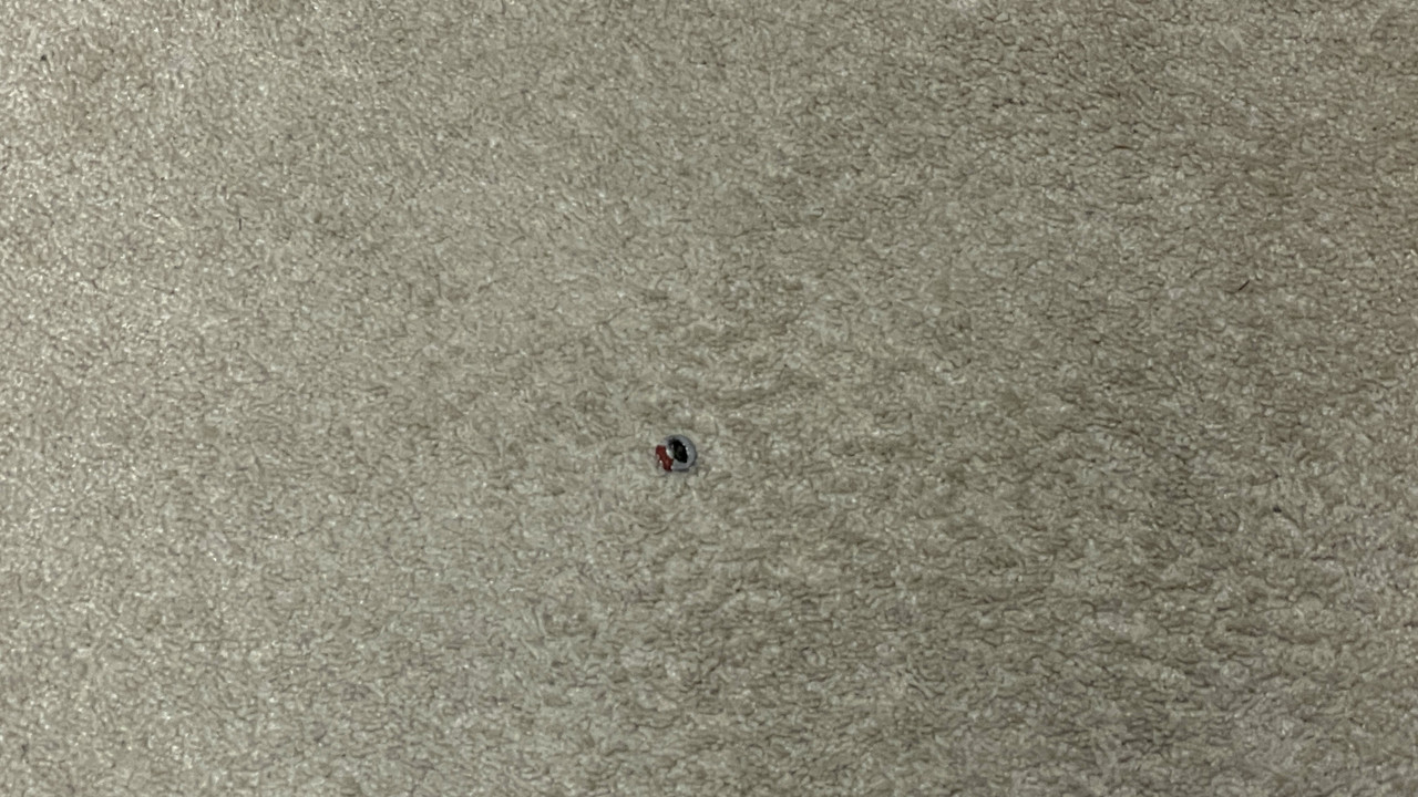
I attempted to install this repaired piece in the car, but the lug was too deep. I took it to the belt sander to “lightly” reduce the thickness. This didn’t work! It broke the piece apart and through the lug end into the ether.
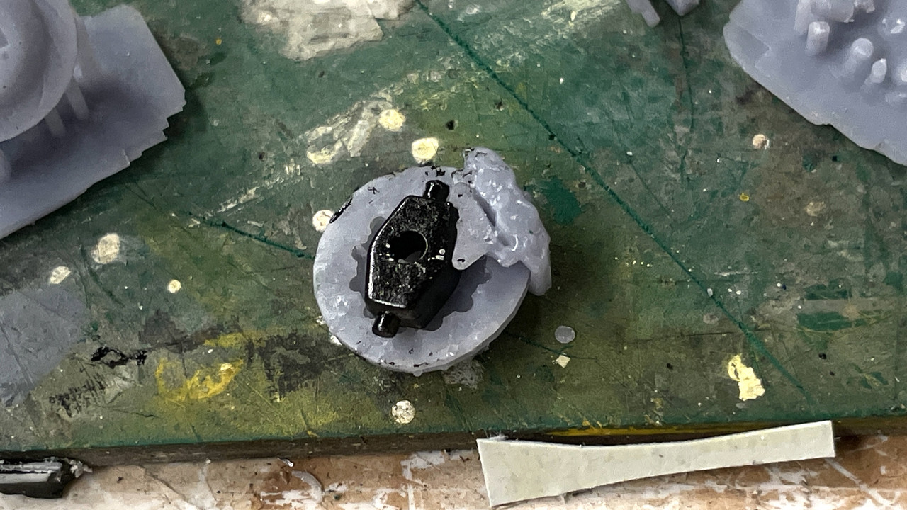
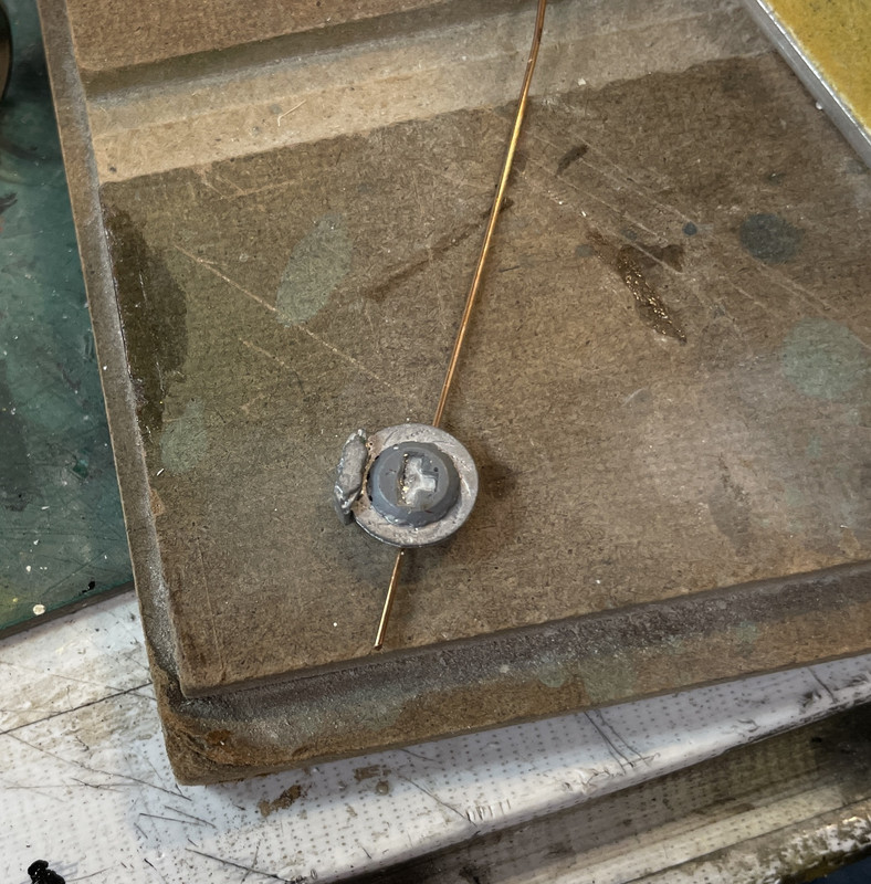
My next attemp had me soldering the cross-pin into the lug, and using this “tail” to stick it into my soldering pad. That stablized the lug end, and then soldering the piston rod as before. This worked!
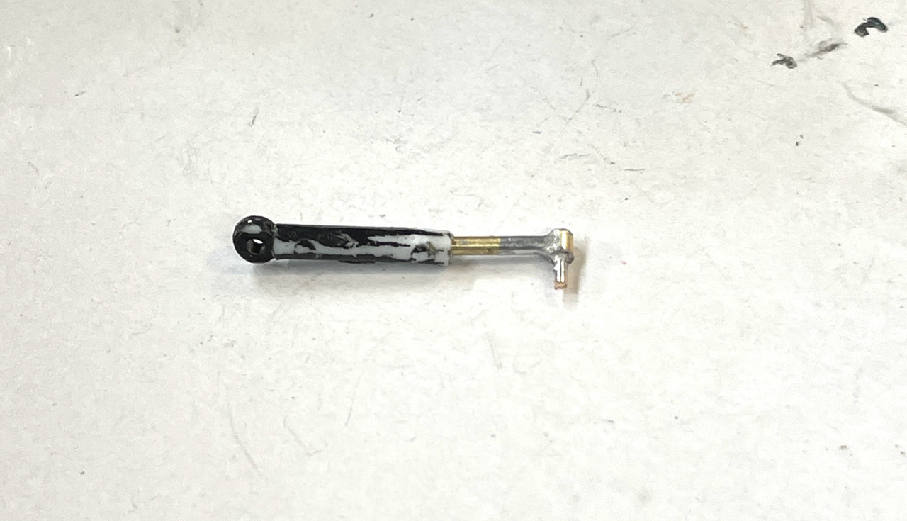
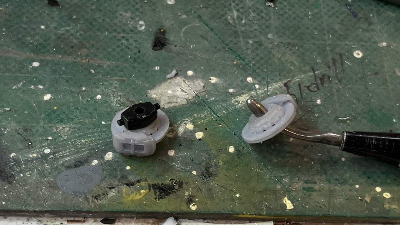
This is the completed shock not yet painted.
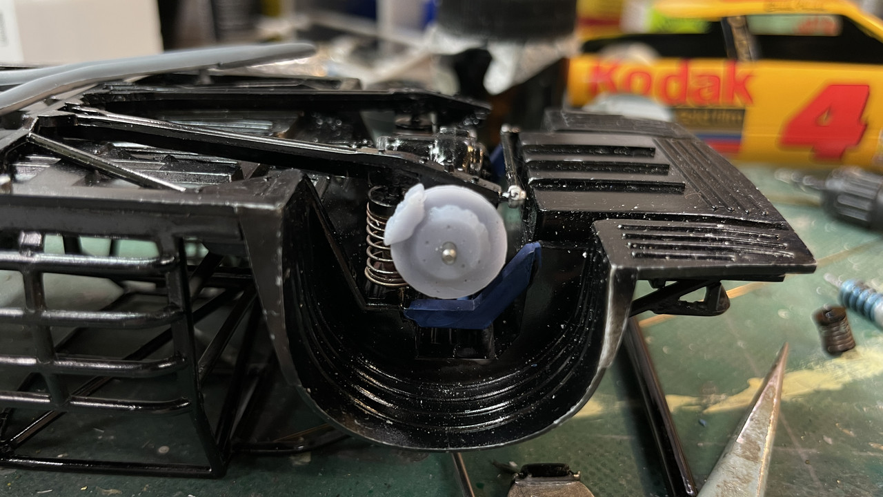
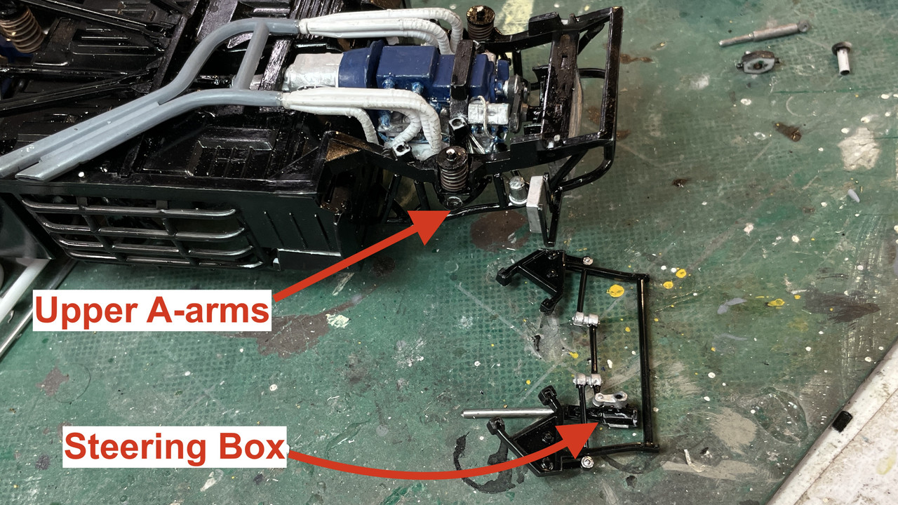
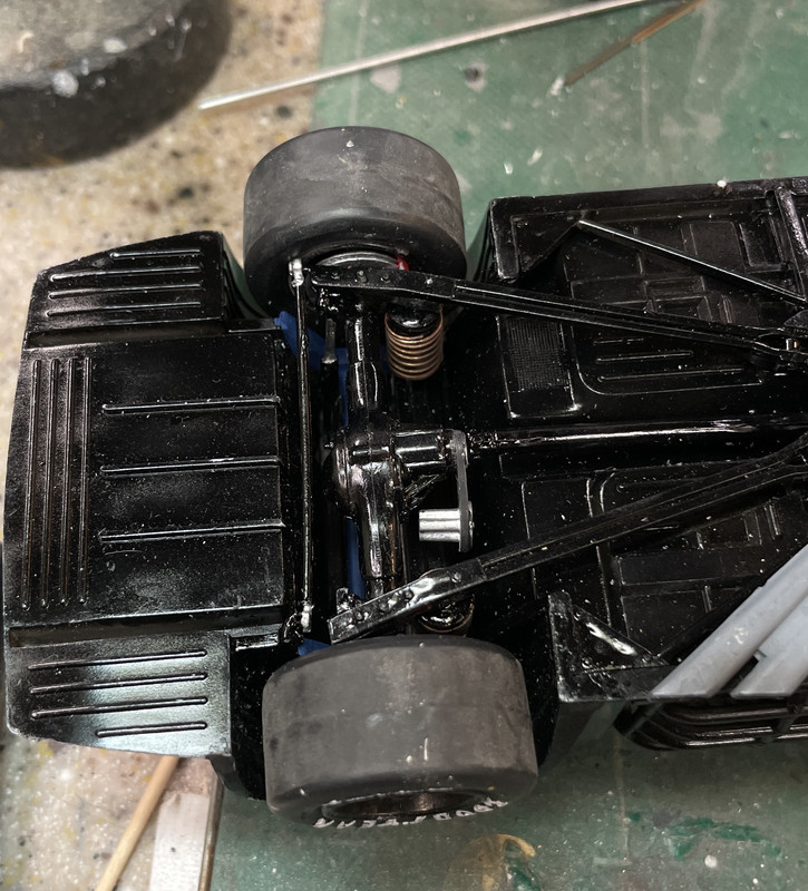
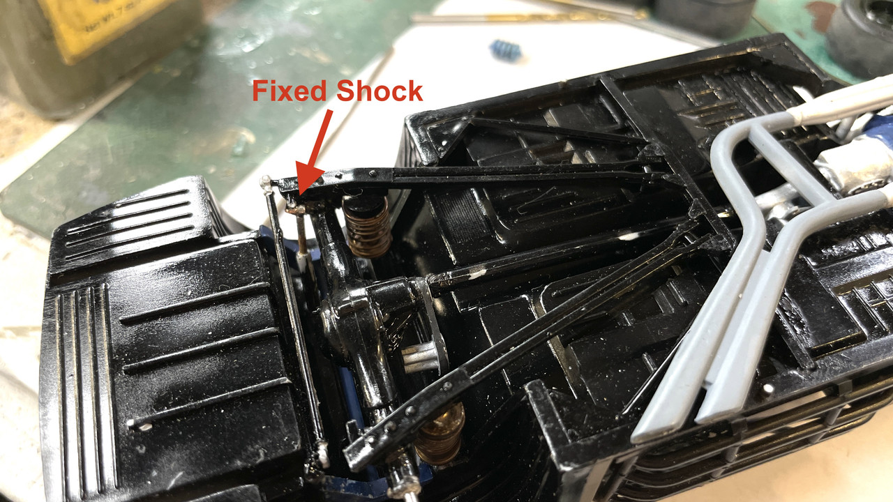
And the shock installed. This wasn’t easy either since the shock mount also had been partially broken in all the tummult. Medium CA with accelerator is holding it together. After repainting I’m hoping that the true poor condition of this joint with not be too evident.
Everybody have a safe and fun weekend. See y’all on Monday.

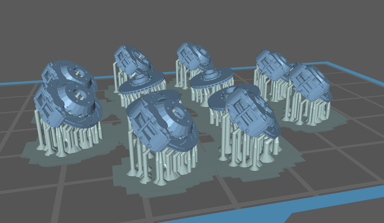
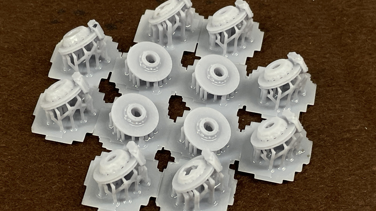
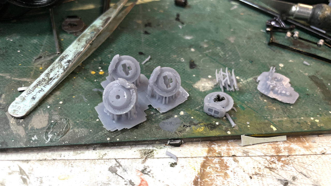
 It’s nice that you can make out the ventilation ribs and cooling channels. After painting it will be interesting to see how well they look. After reinforcing the hub area with Bondic UV Curing Filler, I attached the kit’s steering knuckle. I also had to do some minor surgery on the spring pockets in the front end frame to accept my homemade springs. My springs were marginally fatter than the kit’s and needed some relieving to fit properly. Used the Dremel with Flexi-shaft and 1/16" carbide router.