Kitty Hawk 1:35 SH-60b Seahawk: Start to Finish Build

I just put the Kitty Hawk SH-60b beauty on layaway at the best hobby shop in KY (or probably anywhere) Scale Reproductions, Inc. I didn’t buy it outright because I have a Meng Bradley Busk w/ Interior to do first and I don’t press the model-buying issue with my wife. I build what I buy and don’t buy too far ahead. But this one is special. I buy kits based on interest, complexity, uniqueness, parts count, decal count, and size of instructions. I know, that seems fickle. I don’t have a specific genre, period, service, etc. I just build what I think is cool. If you watched any of my buiids here you’ve seen large scale planes in both WW2 and 1960s all in 1:32 (Tamiya Corsair, Trumpeter F-105G, and Trumpeter TBM-3) plus one old 1:48 Monogram B-17 in “Yankee Lady” configuration. I’ve built a Rye Field Models Sherman M2A3 76W HVSS with full interior, a Trumpeter highly customized USS Essex CV-9 in late WW2 Configuration. I’ve even built a version of the car I owned in College and when first married, a 1966 Ford Fairlane GT-A. So it’s very eclectic. The seahawk just continues that trend. I put it on layaway since I didn’t want to lose it. I didn’t do that on a Rye Field M1A1 Abrams with interior and lost it.

Besides this model being highly rated as one of the best helo kits ever, it can be build with folded rotors which means it can fit on my shelves.

Construction won’t begin for several months so stay tuned. As usual, I will include all the gory details, successes, screw ups and recovery from screw ups.

Good choice. It is a really nice kit. It has a few issues w/the directions though. Here are a few posts that will help out.

https://www.facebook.com/groups/369828906819827/permalink/1042735056195872

https://www.facebook.com/groups/369828906819827/permalink/1042192129583498

https://www.facebook.com/groups/369828906819827/permalink/1042191989583512

Here is a good build article where you can see how it can turn out: https://forums.kitmaker.net/t/kitty-hawk-sh-60b-build/1762

If the links don’t work, let me know and I can send them to you in an email. I have one as well and hope to get to it soon too. We shall see.

Thank you! The links worked perfectly! It’s hard to believe that all those cylinders and hydraulic tubing rotate with the rotors. The fact that it all holds together is a marvel of engineering. I didn’t realize the rotor head was piped, and now that I do, having AMS, I’m compelled to attempt it myself. I also need to get some good reference pics of the engine compartments. I’ve got a good view of the T700 bare with some of its piping, but I’ll need more. You can never have enough reference pics.

Builder 2010;

Hey, is that a model engine you’ve built? If not, it should be. It looks like your work though !

Watching this. I have the Academy kit and a bunch of pe for it ill be starting soon.

I certainly hope my engine comes out 1/2 that good.

Picked up the model at the LHS on Firday. It’s now in the queue.

Picked up the Eduard Mask Set for this model (actually for the HH-60, but I’ll make them work). I just finished the Bradley (on another thread) and will be working on the rick house under-construction for the model railroad. So helicopter building will be in about a month (or less) from now. One of the rotor hub parts for this model are molded in the reverse from what it needs to be to display with the blades in the stowed position. I’ve downloaded instructions on modifying the part (cutting and pasting), but am toying with the idea to photograph it, draw it, reverse it and then 3D print it. If I can do this, I will make the 3D printed parts for sale.

Hey Gang! I’m back. Work has officially restarted on the Seahawk. I was diverted for a few months by two commission projects: a restoration of a large metal commemorative model of a Lockheed Elektra (L-188) that was missing a propeller and stand. The second was a complete scratch-build of a Cletrac M2 High-Speed Service Tractor in 1:48.

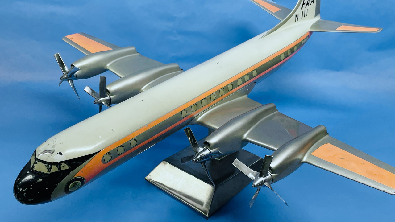
The L-188 was bequeathed to a college student in town by his deceased grandfather who flew this plane for the FAA. I created the stand out of stainless steel sheet metal and 3D printed the propeller from my own drawings. I could have scanned one of the other props, but don’t have the capability. Results were appreciated by the client.

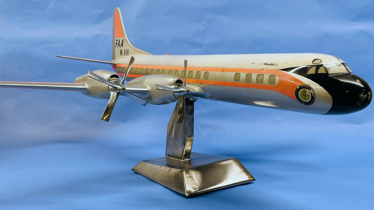
To simulate real metal on the resin prop, I decanted the liquid metallic ink in a large tip Molotow Chrome Pen and airbrushed it. It was a suggestion from the hobby shop and worked great. So great that I’m using the chrome ink as a paint instead of in a felt point pen.

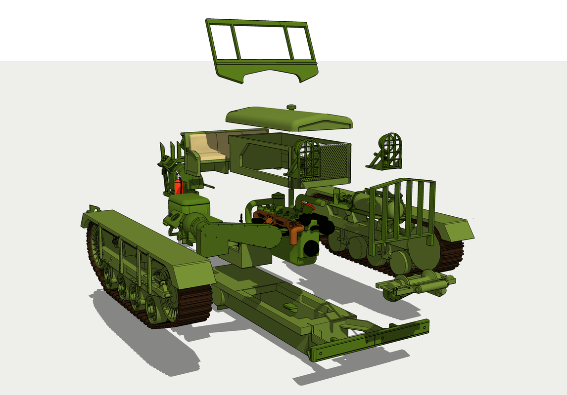
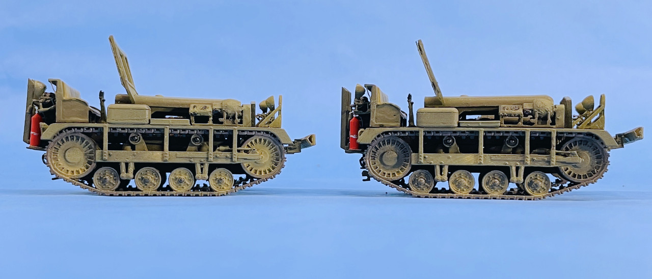
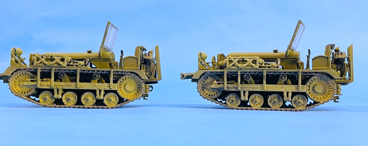
The M2 was created entirely by my drawings based on images found on a Google search. The Cletrac (Cleveland Tractor Company) M2 was used throughout airfields in WW2 to tow our bombers on un-improved air fields in Europe. I found one line drawing that has overall dimensions that helped me scale it corretly. The model parts are produced on my Elegoo Mars 3D LCD Matrix resin printer and consists of a number of sub-assemblies.

Here was the exploded drawing showing all the parts and how the.y related to each other.

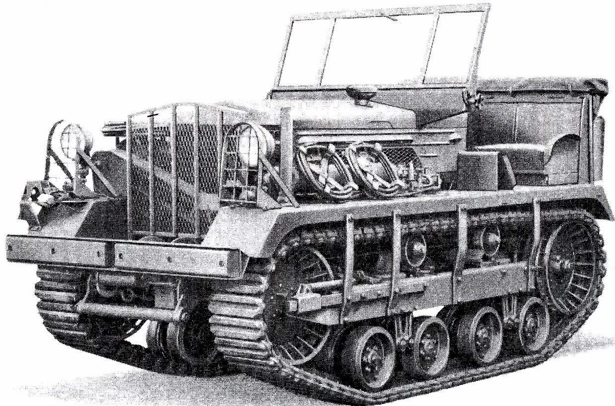
And here is a prototype drawing. This was the one that I used in the SketchUp Match Photo process to draw directly over it.

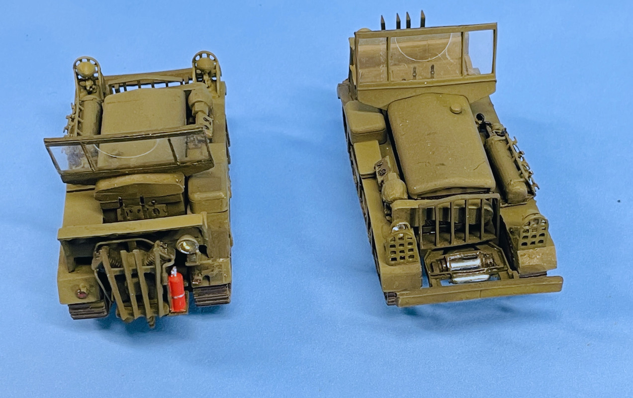
And here’s the complete model. I made two. One for the owner of Scale Reproductions, Inc. (one of the best hobby shops in the USA) and one for display in the store.

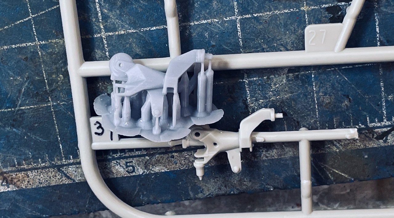
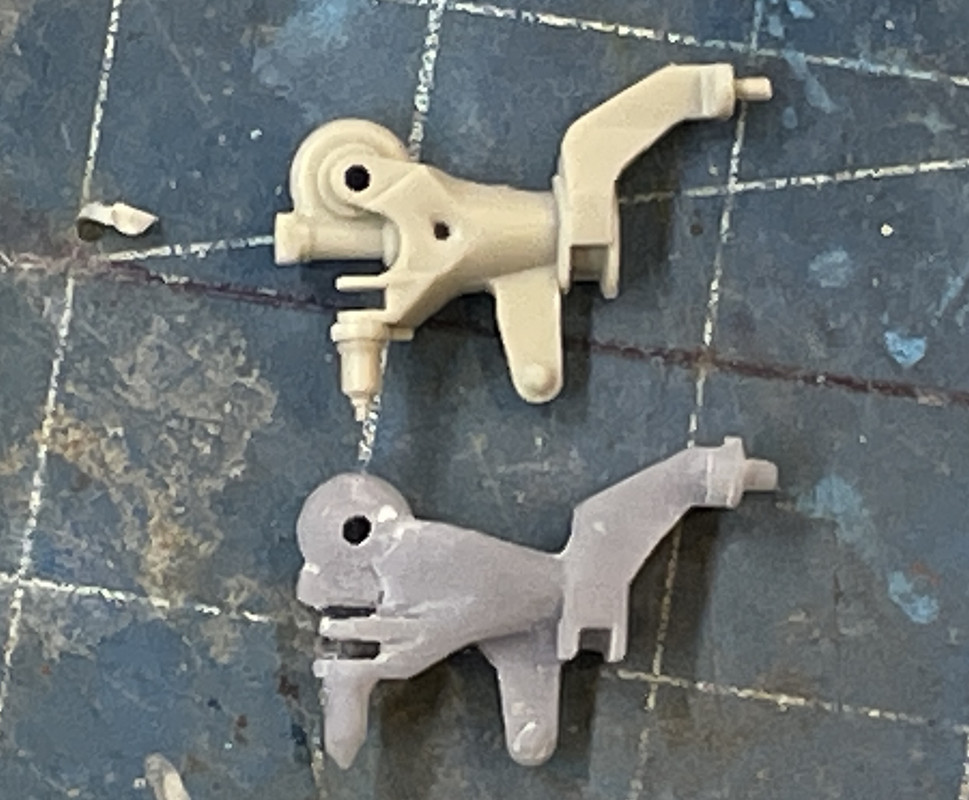
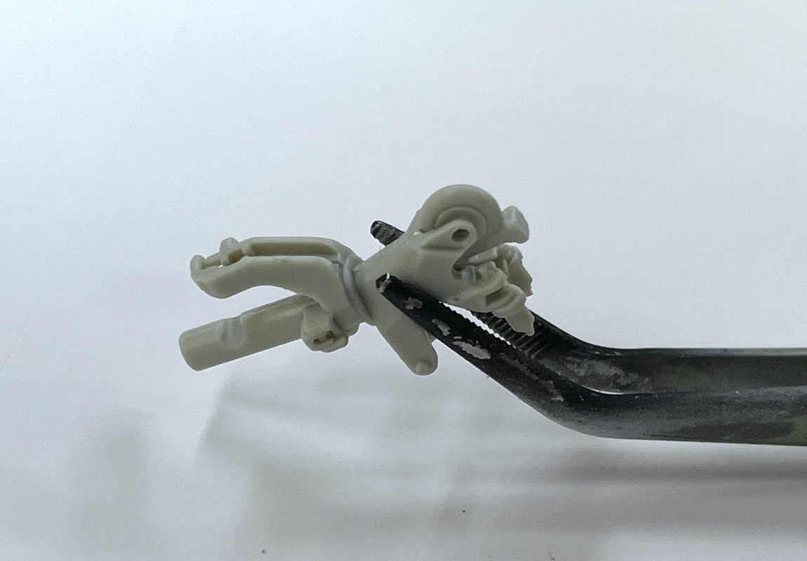
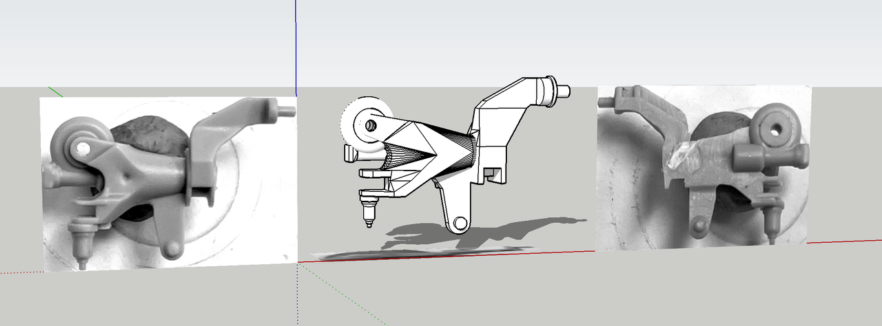
Now onto the Seahawk. I firmly decided not to procede with the cut and paste method to create the correctly-facing rotor head component, sprue numebr HD33, but instead decided to attempt to scan it with my newly acquired iPhone 12Pro with the LIDAR range finder. I found a scanning app that I thought would do the job, but it really didn’t work. It could focus the process down to less than a half meter, but the resolution was horrible. The resulting STL files were just a jumble of lines looking kind of like a Alexander Calder modern art creation and bore no resemblance to the actual component.

So I went to plan B. I imaged the part in three views and drew it in SketchUp. Since SU doesn’t like working in tiny sizes, after measuring critical dimensions I set the scale to 100X larger. After fully drawing the object I shrank it to .01 and exported it as an STL file for the printer.

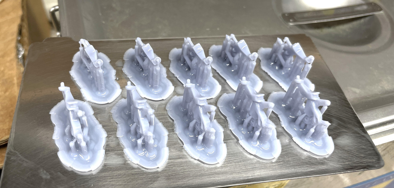
I attempted to print a bunch, as you can see in this screen shot of the printing scheme.

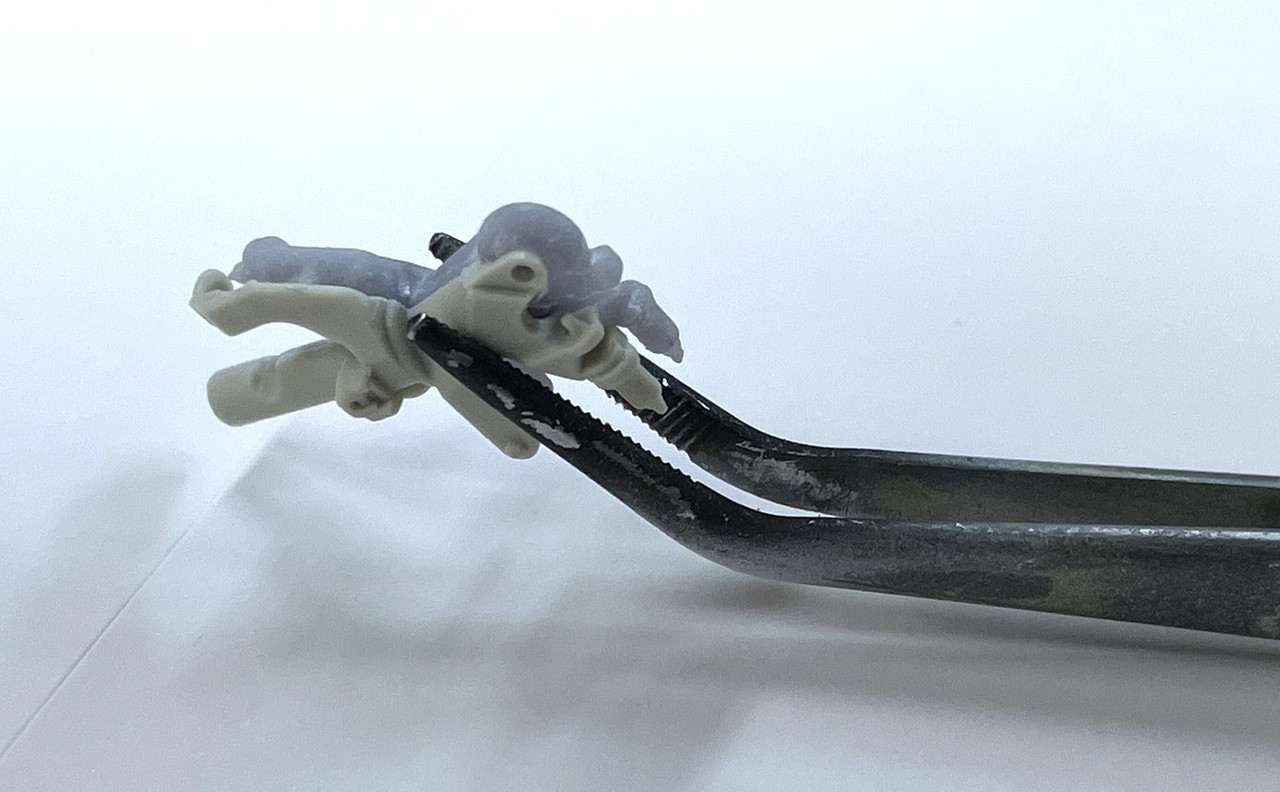
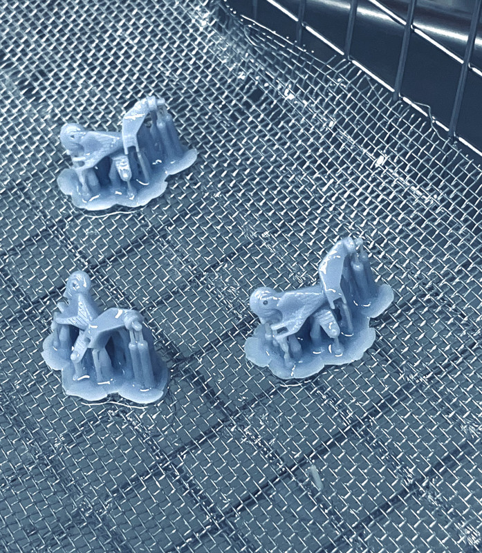
Unfortunately, only three stuck to the build plate, the remainder sticking to the Teflon at the vat’s bottom. I got three good ones as seen here in the ultrasonic cleaner’s basket. The little down-facing arm is very thin in cross-section and I’m not sure if it will hold up when I remove the supports. To fix that, I thickened the arm in the drawing and will try and reprint. I’m thinking of making these fixed parts available for sale.

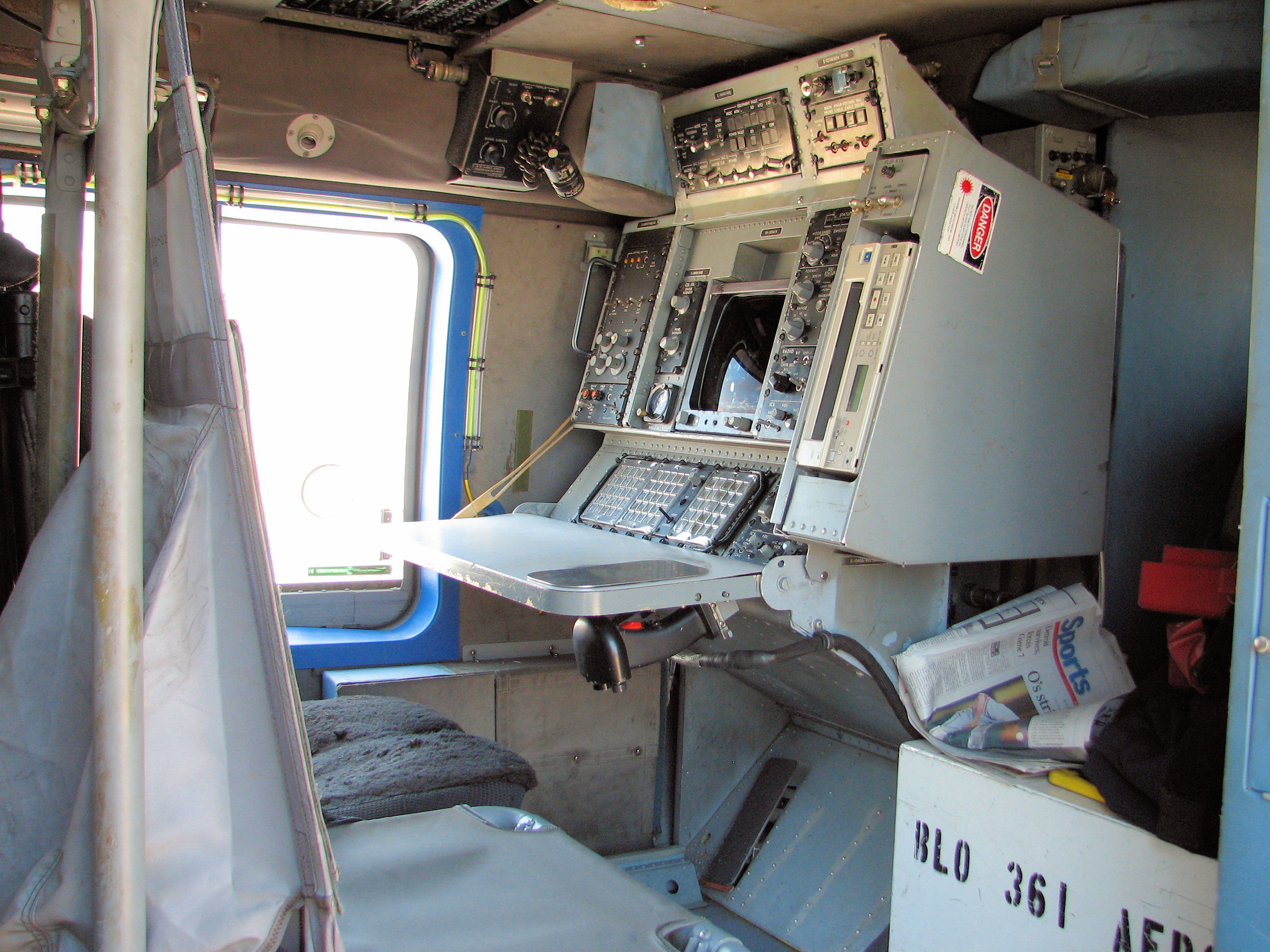
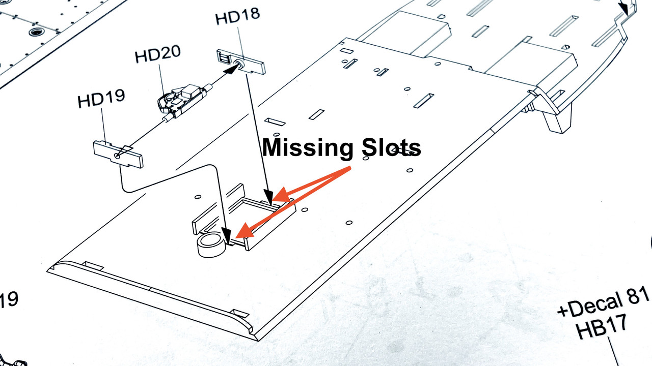
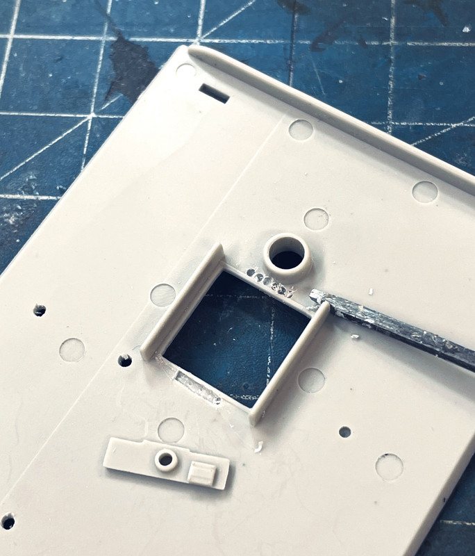
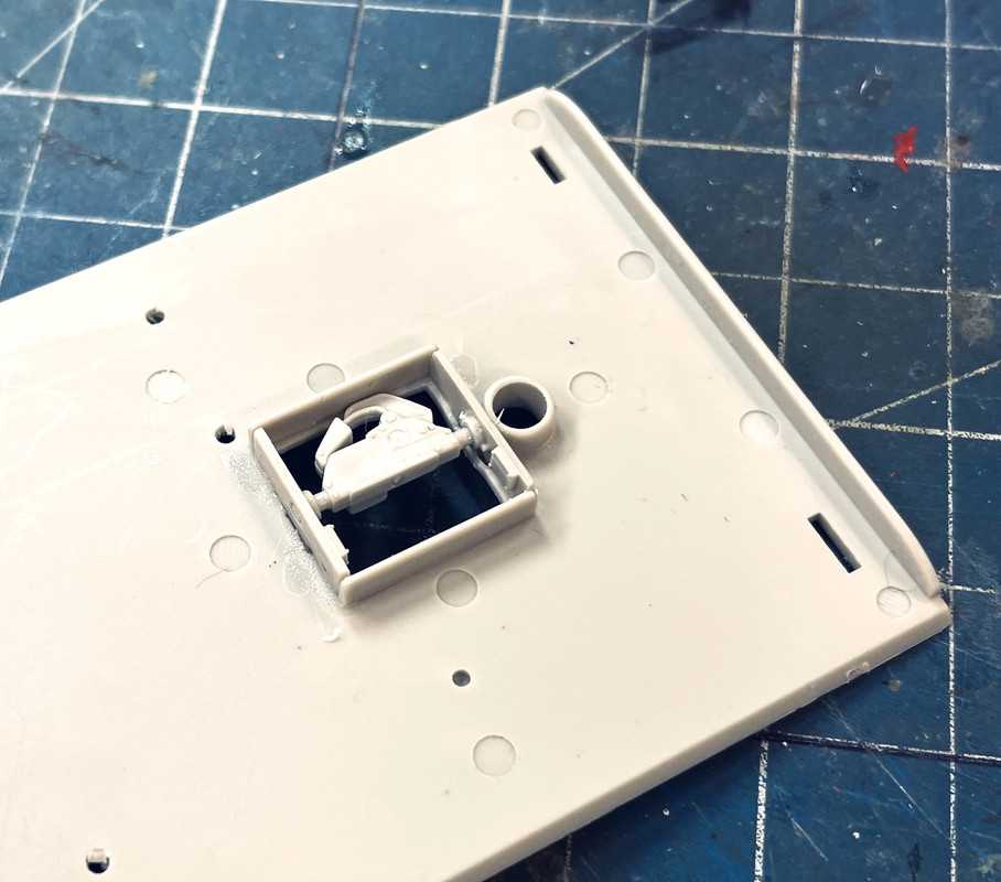
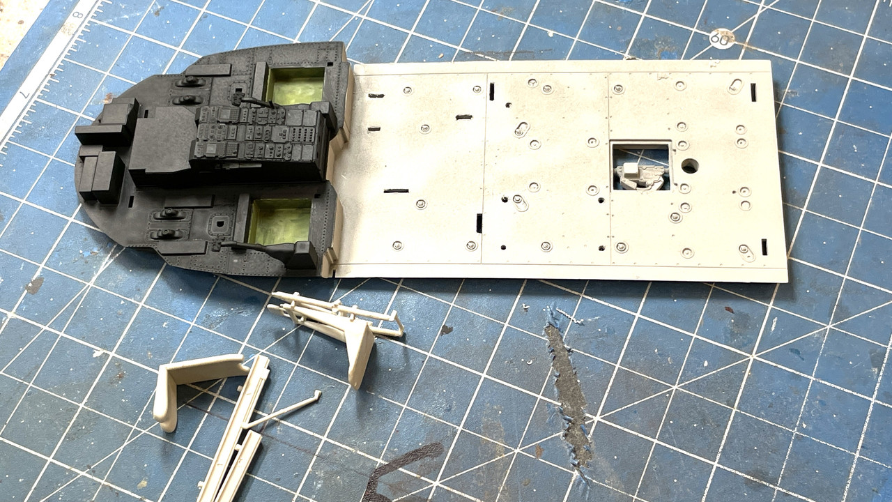
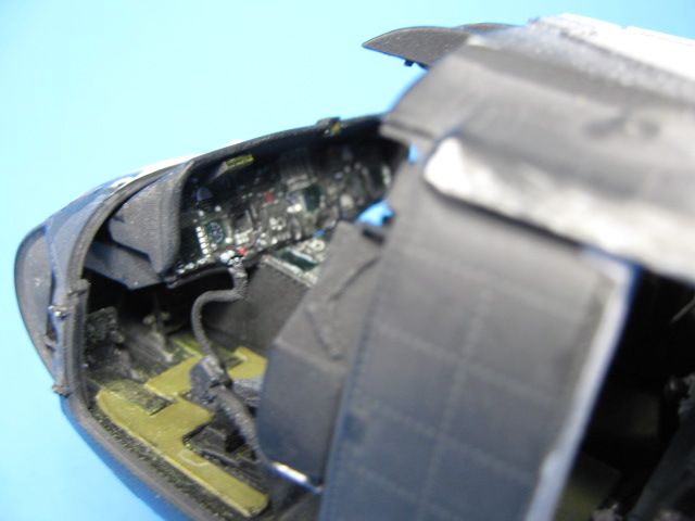
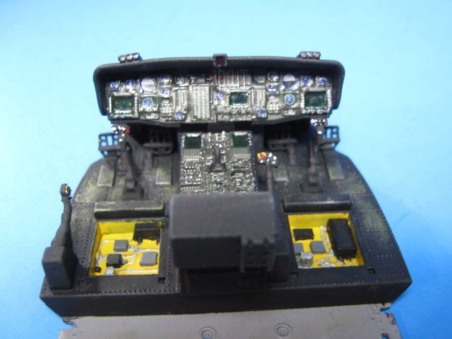
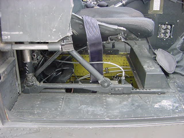
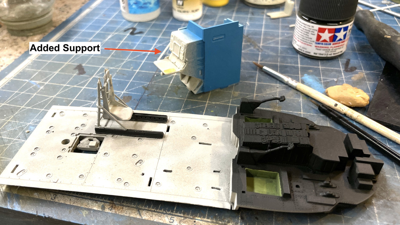
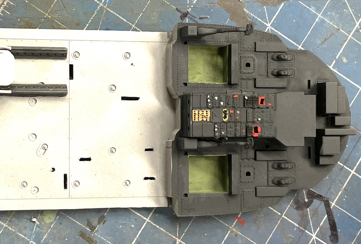
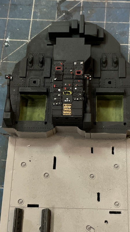
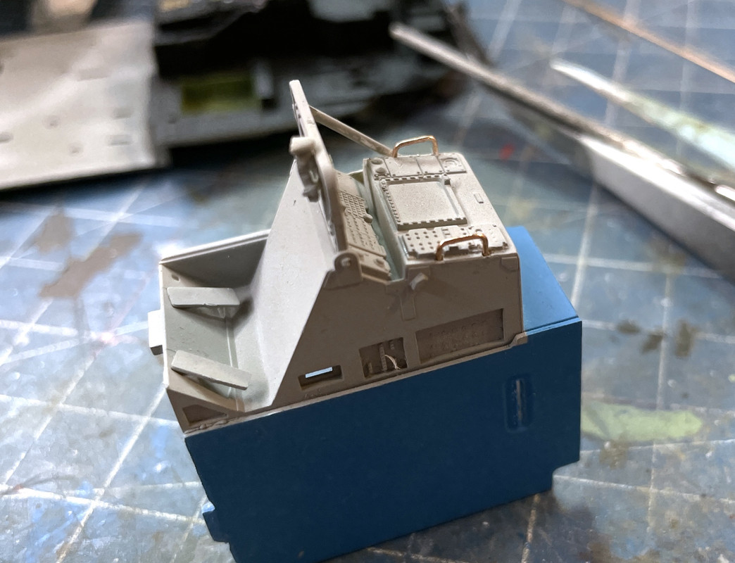
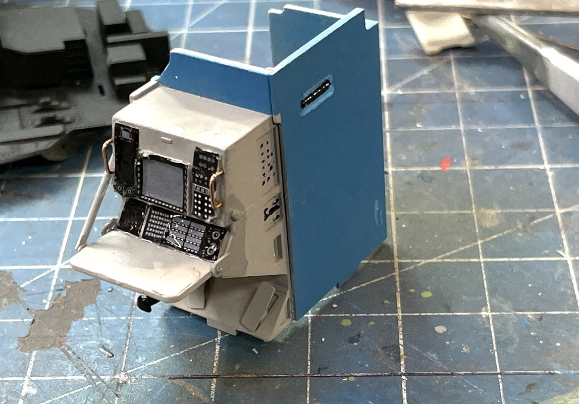
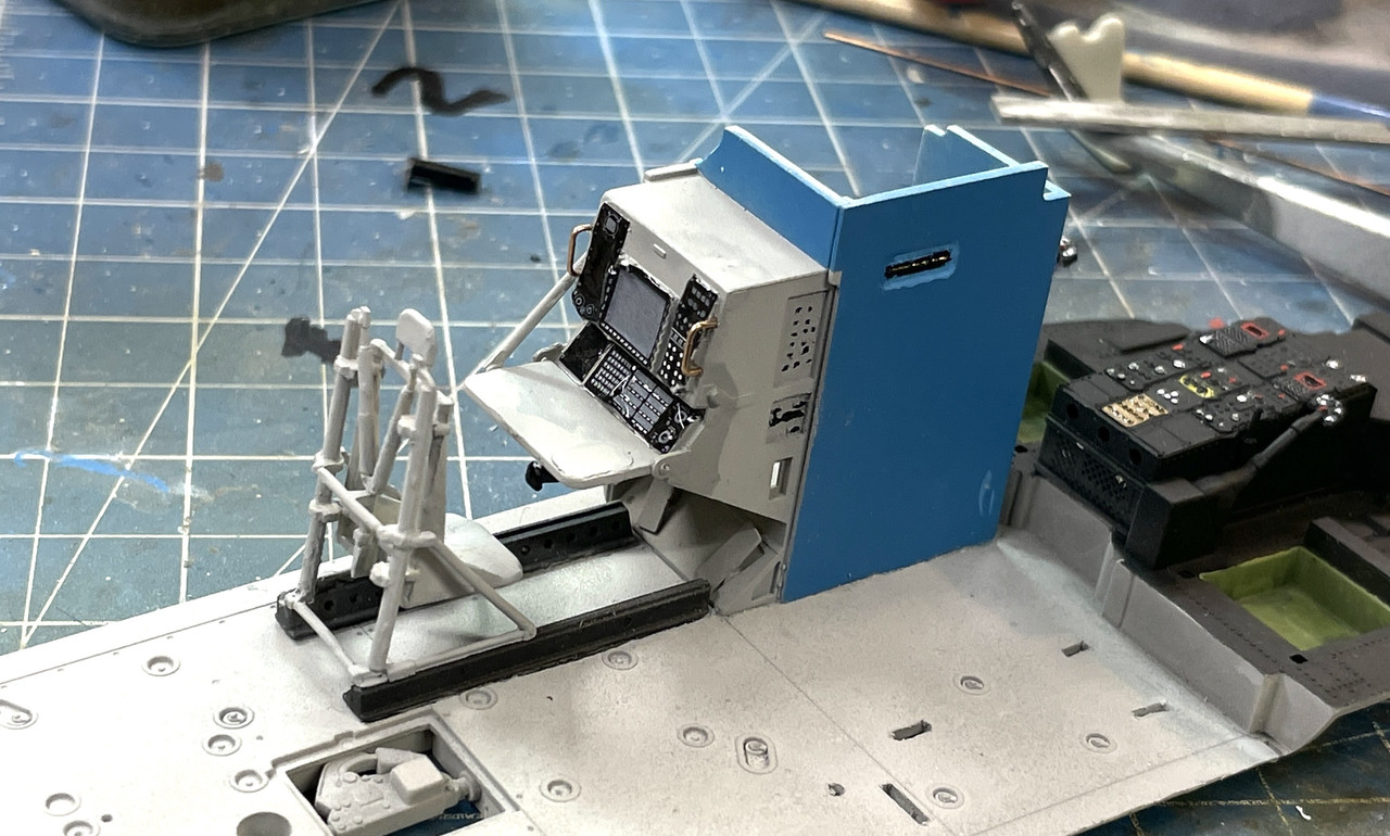
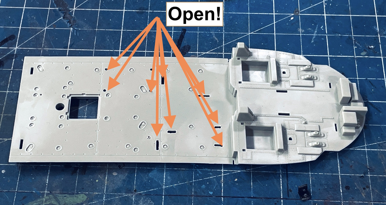
And I actually started working on the model with the preparation of the floor. You have to open up a bunch of slots and holes since this pan is also used on other versions of this helicopter incluing the army version, Black Hawk. This naval version has all kinds of anti-sub apparatus inside and these pieces needed mounting on this floor.

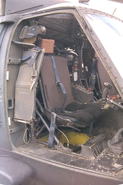
And point of information: what is the interior color of this ship? The instructions do not identify the basic color. They do note flat black on various parts of the interior, but not for the entire surface.

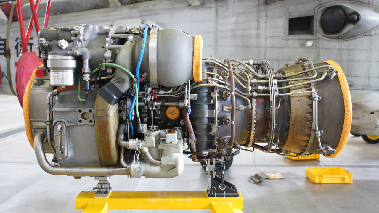
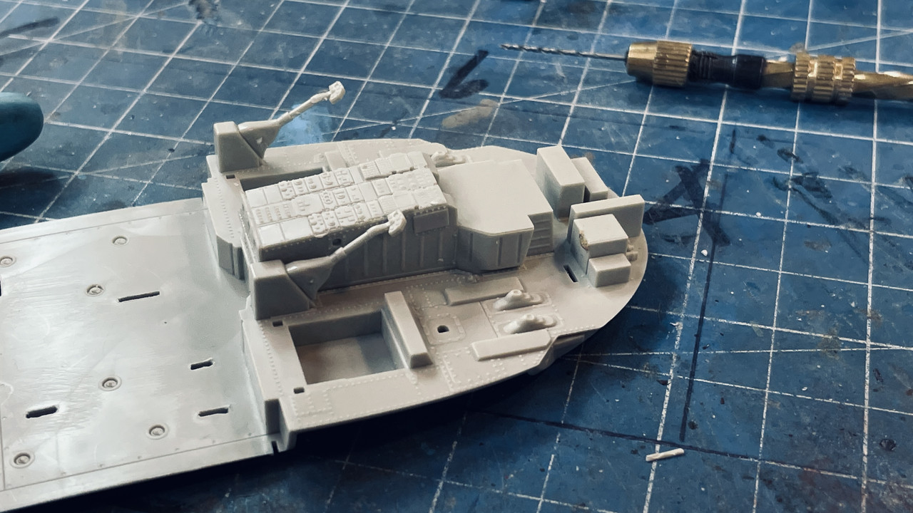
I’m going to have a lot of fun super-detailing the gas turbines that power this model. The engines do have some of the larger piping, but there’s a lot more that can be added.

And due to the massive print failure, I have to change the teflon. I damaged it when trying to remove the stuck remains of the failed parts.

If any of you following this thread are going to build this model and would like a replacement HD33 rotor head part, let me know.

Good deal. I have been waiting to see how you tackle this one.

Actually, only the Navy versions use this floor part. Kitty Hawk uses a totally different floor and interior parts, as they shoud since they are very different, on the Army MH-60L Black Hawk and the USAF HH-60G Pave Hawk kits.

The rear cabin interior has light grey metal parts and medium blue plastic and fabric-covered parts.

Everything forward of the step up on the floor (entire cockpit; walls, IPs, ceiling, seats, etc…) is flat black to be NVG compatible.

A full SH-60B walkaround with interior shots can be found at Prime Portal: http://www.primeportal.net/hangar/michael_block/sh-60b_sea_hawk/

Once again, Gino, you came through. I will check out that walk around.

I cleaned the HB33 part, but haven’t separated it from the support system or did any post-processing on it (drilling out the hole to correct diameter for instance), but you can get a reasonable idea of how close my rendition is to the actual part. I believe it should work. If it fits, it won’t be detectable after painting.

This image shows something else for those interested in 3D printing. My newly adopted support scheme has been pretty successful. I let the slicer automatically place heavy supports first. Then I go back and remove all of those that are connected to the delicate areas and replace them with my custom-designed medium supports. These have a heavy weight stem so they don’t fail, but have a light weight end termination so they don’t damage the details when I remove them. The slicer shows you where the supports need to be placed when you rotate the part view in the slicer. Any areas that are going to fail are highlighted in red. The brighter the color the more in jeopardy that area is.

I found that using the default medium and light settings also made very thin support legs which often failed due to the pulling forces encountered in the printing process. By thicking the legs, but keeping the tops narrow I got the best of both.

The 3D printed HB33 part came out looking good. Should be a good fix.

I am eternally envious of the guys in these model companies that must work from actual drawings, and how they’re able to covert them to prototypes and then cut dies for them. The real test will be when I clean it up and how it fits. If it fits it works!

I went to that website and downloaded some more images of details to concentrate on.

My 3D printed rotor part was almost right. It needed some very minor tweaking which I did on the drawing. I checked it by mating it with the other half and was able to determine the interference fits and hole placement. I then attempted to print 10 more. I had a brand new FEP film. This time I used one of my Elegoo sheets. I’ve had bad luck with these, but decided to give them one more chance. It was a total bust. What didn’t stick to the flim failed anyway. I’m putting another EPAX film on tomorrow. I haven’t had a failure like this in quite a while and it worries me a bit.

That said, I continued working on the model itself.

The assembly of the floor started with puting what looks like the hoist motor that goes under the floor. It’s held with two end pieces which were supposed to have notches in the floor surrounding the opening. The notches actually weren’t there. There was a hint of a slot, but it didn’t work. I could have cut the tabs off the pieces, but chose the oppositie route; cutting new slots. The instructions clearly showed these non-existent slots.

I started by drilling a series of holes partially through the thickness. The trick was to stop drilling before I cut all the way through.

I then used a tiny chisel to open the slot to accept the tab. I did have to shave a bit off each piece so they would settle down flush.

Here is the assembly done.

I glued in the center console, it’s back piece, and the two collective pitch levers that sit to left side of each flight deck seat.

I downloaded even more good images of Seahawk interior showing the color of the floor material, wall, and cockpit area. I airbrushed the cabin floor a Tamiya light gray. I masked the cabin off from the cockpit and painted that with Nato Black. I like using Nato black instead of flat black in a lot of instances. Most things aren’t pure black in use. The pictures of the cockpit showed that the black is not pure black.

I then sprayed it with Dullcoat to prepare it for further coloration. The first place this occurred was in the box area under the seats which I saw in a picture was zinc chromate. If you look closely under the seat you can see the area I’m talking about.

Here’s the floor pan.

Also shown in the above is the beginning of building the first seat…the weapons offcer’s. The contact point for the seat frame to the back frame was tenuous at best and took me 10 minutes to actually figure out just how it was supposed to connect.

There are decals for all the instrument panels, but I’m not so happy with them. I may just go old school or order the Eduard set. The decals would never settle into all the texture on the panels. If I have to scrape it all off, I might as welll put in a PE interior.

Just checked. Eduard has an MH-60 interior, but not the Seahawk. The instrument panel is updated with more displays and the center console is very different. I’ll go old school.

Looks like you are off to a good start. I used the decal instruments on both my KH 1/35 MH-60A backdate and HH-60G models. Surprisingly, with a bit of decal solvent and decal set, they snugged right down with no issues. They look really good too.

Also, in the openings below the seats, there are electronic boxes and wiring. You can see how I did it above and the actual openings below.

You should post this over at the Aerscale Rotary Wing forum too: https://forums.kitmaker.net/c/aircraft-scale-modeling/rotary-wing/16

How did you determine what boxes go down there? I was wondering why that space was there. There’s also a “no-step” stencil on the bulge on the front of the boxes.

First of all, I was finally able to nail the printing problem I was having earlier. I dumped the Elegoo Mars FEP film (one use) that failed miserably and replaced it with my standby EPAX Non-FEP film that seems to work much better. I also redesigned the part further to improve its accuracy and more refined. Lastly I increased the raft size under the part. I set up to print 9 more. And the print was perfect. They’re now cleaned and in the post-UV cure chamber. Due to their delicate nature, I harden them before removing supports and use a needle shaped, diamond coated burr in the Dremel flexi-shaft to cut off the supports without shocking the part. I get pretty good results doing it this way. Even flush cutters can impart enough shock to break small details.

I’m going to make these parts available to anyone who’s building these kids for a very small fee. The only caveat is you can’t use solvent cement since it doesn’t affect the cured UV resin. CA is a must.

I got the weapons ofc seat finally installed. I said it many times before. I’m not a patient person. I am a very persistent person. When I screw up, it’s because I haven’t let glue or paint dry sufficiently to permit moving to the next step. Case in point… I glued the seat together using solvent cement. Thought it was sufficiently dry to handle and finish painting. It wasn’t. It fell apart and re-gluing got more onerous the more I attempted it. Finally I resorted to med CA with accelerator. if I would have left the seat cure overnight, it wouldn’t have happened.

The above also shows the weapons console (or whatever it’s called). The images I have show it to be light gray and the interior walls a light blue with a little green in it. The fold-down work tray has a separate hinge piece on the far side that captivated the pins on the tray. The tray also has a separate hand controller that gets glued underneath. One the prototype there is a retaining bar on the outside that is not present in the model. I added a piece of styrene (over-scale) to positively hold the tray in position.

It then started painting the center console. I have a great picture showing each knob on it.

I didn’t finish the painting, but it’s getting there. I’m attempting to make that red band around the CRTs in the cosole. I’m not there yet. I could make a custom decal or cut the screen’s decal out of the total console decal.

I’m letting all the blue paint dry before doing anything else. It’s Vallejo. Valllejo flashes off quickly, but doesn’t really dry for 24 hours. It’s one of my complaints with it. I’ve also used Life Color of some of my naval models and find it much more controlable.

I guessed what under the seats looked like. I can’t find any clear pics and they are just boxes and wires. I took kit part HB4 (B18 in the MH-60L and HH-60G kits), which is only seen if you build it with the nose compartment open, and cut it up into two squares that slide down into the under seat compartments. I added a couple more boxes and wires to fill the area up as well. Once the seats are in place, you can’t see much anyways, so they look good enough.

Don’t know if I’ll add it… but I might not be able to help myself (AMS). Got a very little time in the shop, but did get the latest iteration of the HD33 rotor part cleaned up and checked. It’s still a tad off. The donut and its hole are a scosh to far out so the hole didn’t align with the kit piece. If I want to make this available to others it needs to be just about perfect, so I’m printing another modified bunch (Ver 3.0). Notice tht sink hole in the plastic part.

And I did some more fine detailing on the center console. I’m thinking I’ve gone as far as I can with this part. And now I have to decide to add some greeblies in those equipment boxes under the seats.

I’ve also been introduced to some terrific resin details by ResKit that I’m having my LHS order for me. Actually the proprietor showed them to me. I’m getting them. Since I’m gong nuts on this model I might as well go all-the-way nuts.

Good deal. Of note, if you get the Res/Kit SH-60 rotor head set, it replaces part HD33 with their own parts, so you may not need to continue on it.

Here is a link showing the Res/Kit Naval H-60 sets. https://forums.kitmaker.net/t/news-res-kit-1-35-naval-hawk-update-sets/7793

Since I did order the rotor head, your point is correct, but, I still perfected the HD33 piece as best I could using the print method available to me, so I will have those parts and can make them available to folks who rather spend a couple of bucks (USD) than to shell out $35 for the complete assembly.

To that point, my latest mods to the part brought the holes in perfect alignment, got the size matched to the blade lock cylinders, and further refined the overall shape of the other end with the arm with the pin on it. Here is it in position with the mating kit’s part.

If I could only print without those pesky supports, the part would be essentially perfect.

Here’s the fit of the correct part included with the kit.

I’m going fully assemble the kit’s rotor just for fun and compare it to the ResKit parts.

I finished up work on the weapons console. I didn’t like how the plastic hand grabs were fitting so I made some out of 0.022" phosphor bronze.

I chose to add the decals using a lot of Micro Sol and Micro Set after applying some Tamiya clear to provide a better surface.

I then glued the completed console onto the deck after scraping off the paint in the glue area for a good connection.

That finishes up the work for the week. See y’all on Monday. And Happy Halloween!!!