The sonar panel is looking nice. Good job on it so far.
Thanks Gino!
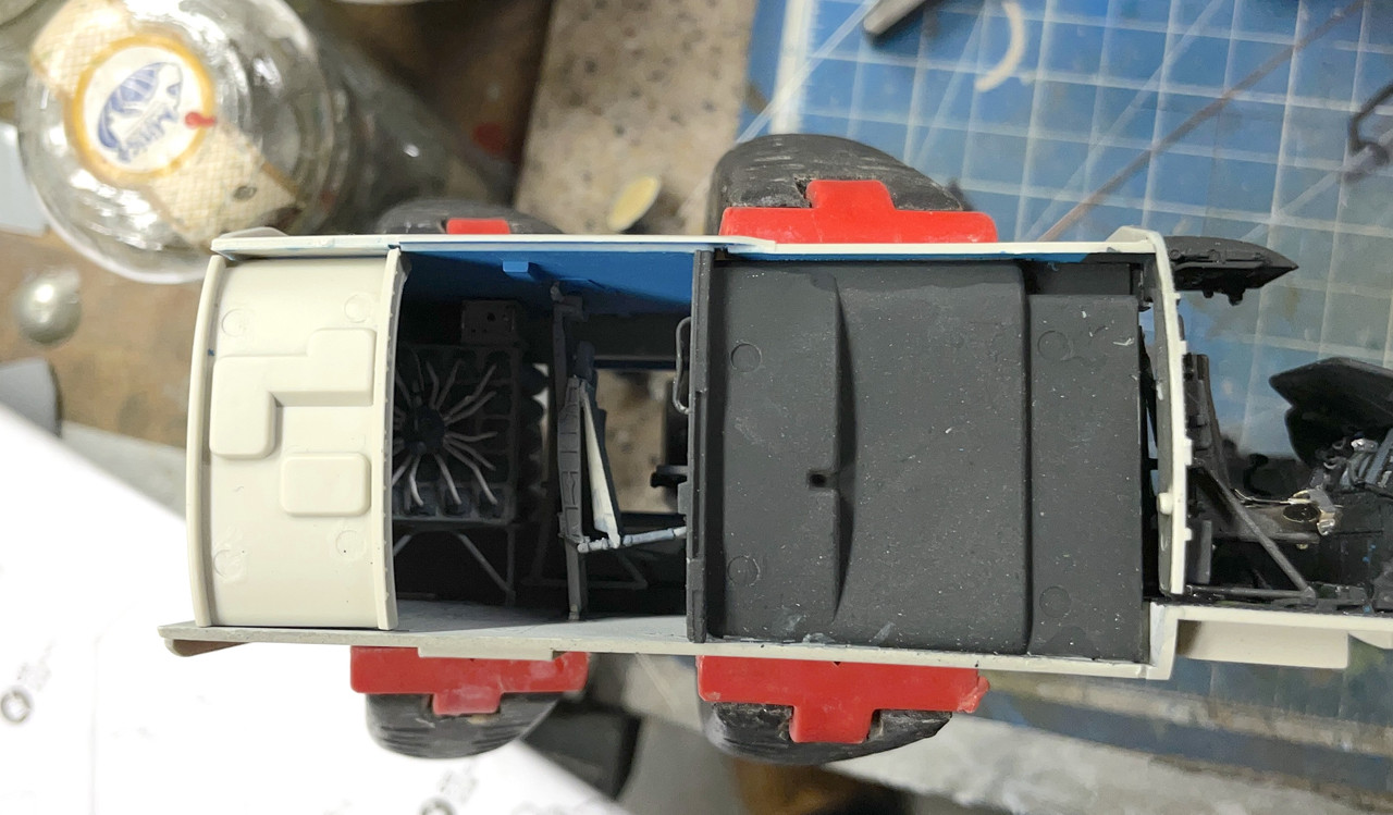
Finished the console area with some flat clear, added color to the underneath area, a coupld of floor details and the right hand bulkheads. I needed to mix more of the blue wall color. It’s not an easy mix of blues and a bit of yellow. I adjusted lightness with white. I made enough so I could airbrush it. I reuse all my screw-top airbrush bottles. After cleaning any dried paint with MEK, I plop it in the ultrasonic cleaner for 10 minutes and the bottle is sparkling.
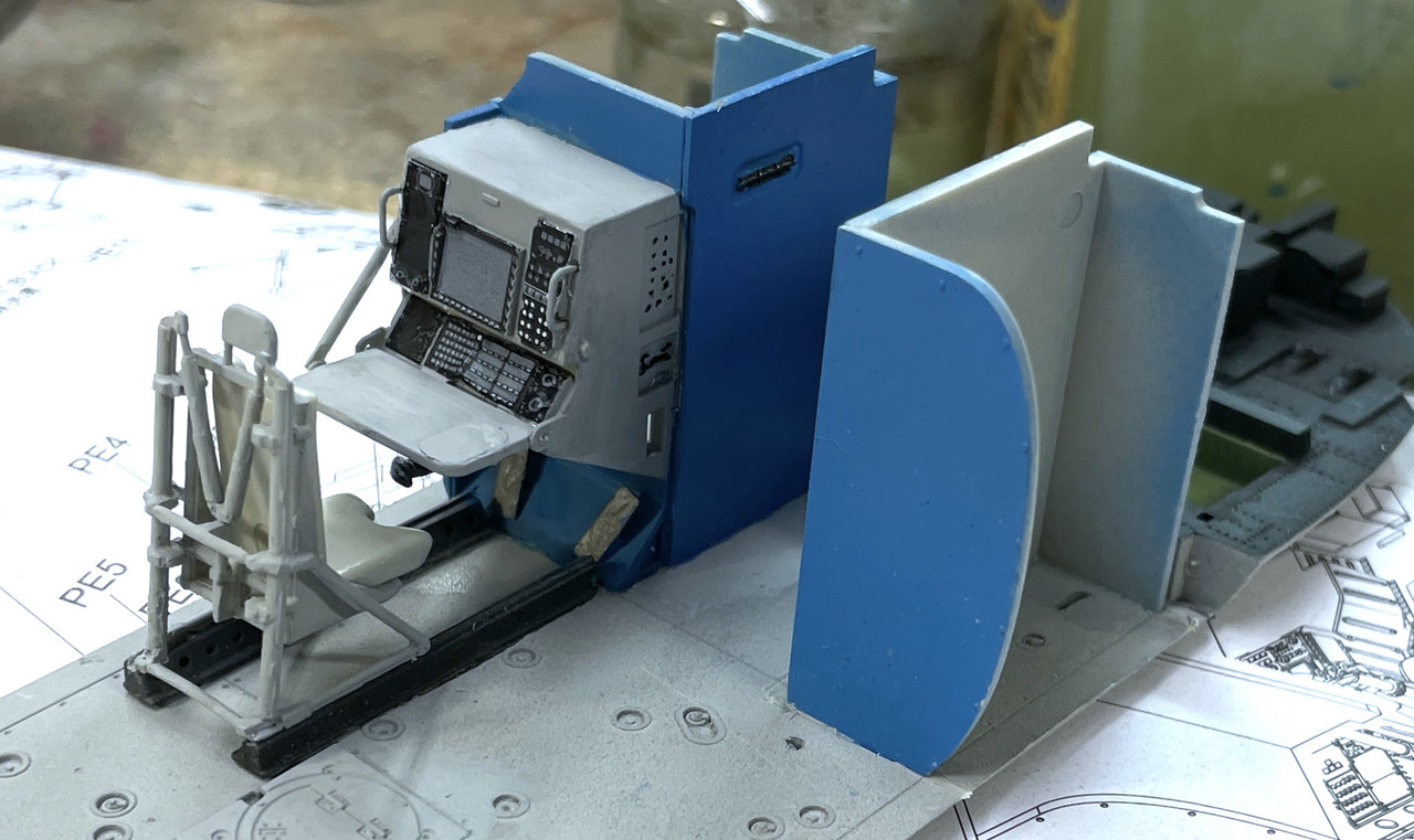
I started building the cockpit seating. Again, getting the little pins on the seat bucket to engage in the spots on the seat frame was a pain in the behind. I wised up and drilled some small 0.022" holes for the seat’s pins to find and it was much, much easier.
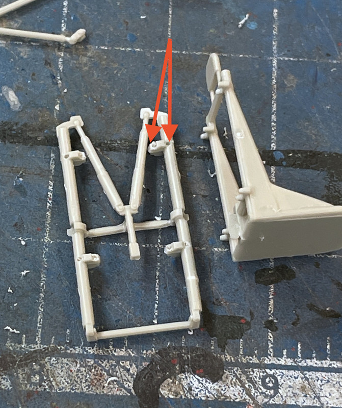
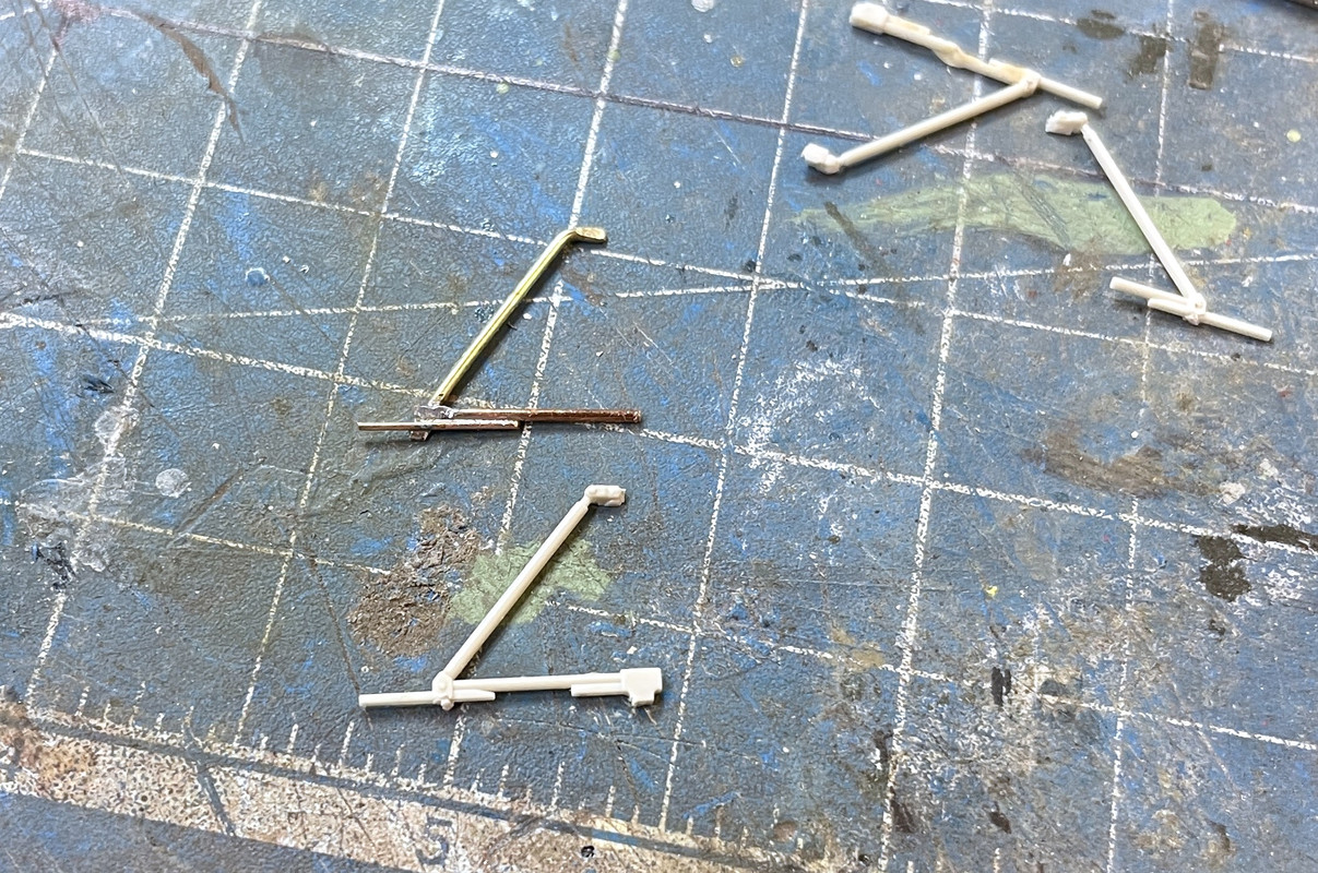
The angle braces for these seats presented another more tractable problem; two out of four of them broke in the same place. I first attempted to glue it together. First supporting it in some clay with solvent cement.
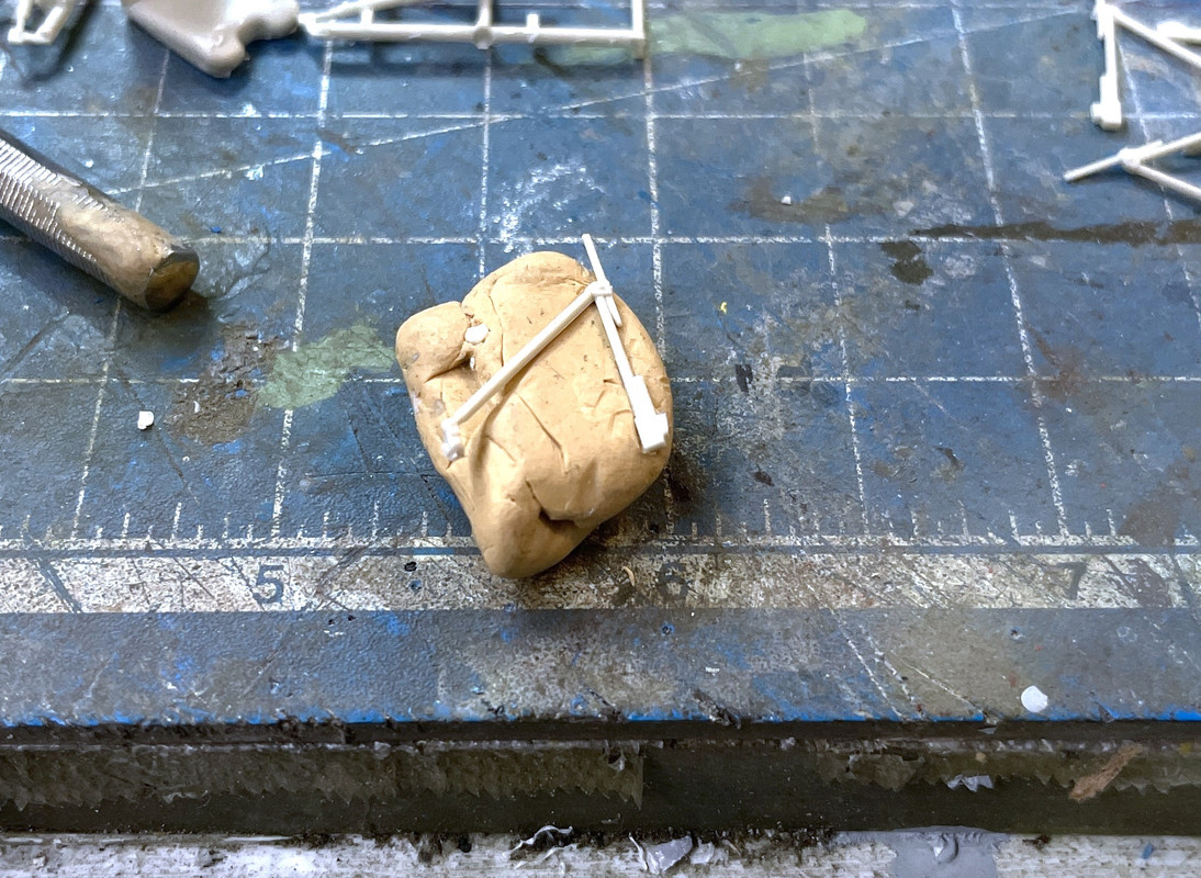
Didn’t work. Second attempt: glue it together with Bondic UV resin.
Didn’t really work either. Plan B: make my own out of various pieces of wire.
I have the tools to work with fine metal pieces. I solder all the PE together on my 1:350 ship model antenna towers, so this shouldn’t be too bad.
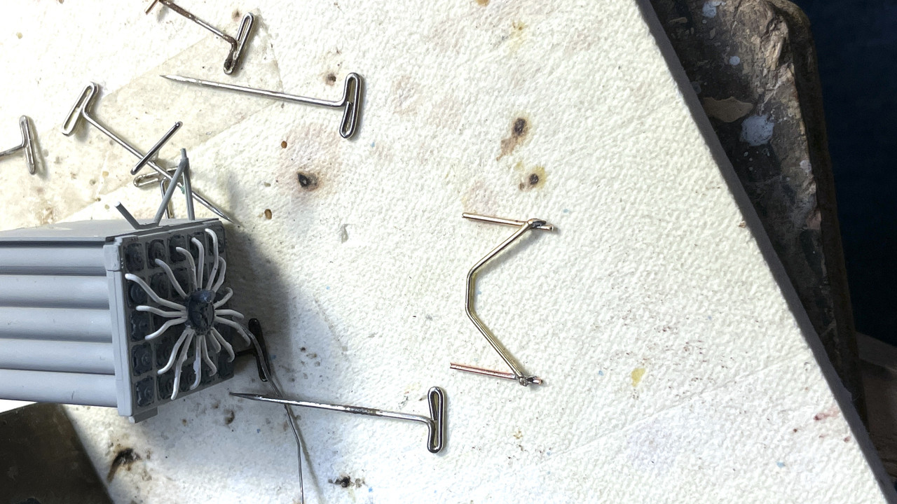
Measured, bent and cut using one of the two good ones as a guide. I have a ceramic soldering pad that lets you pin things in position.
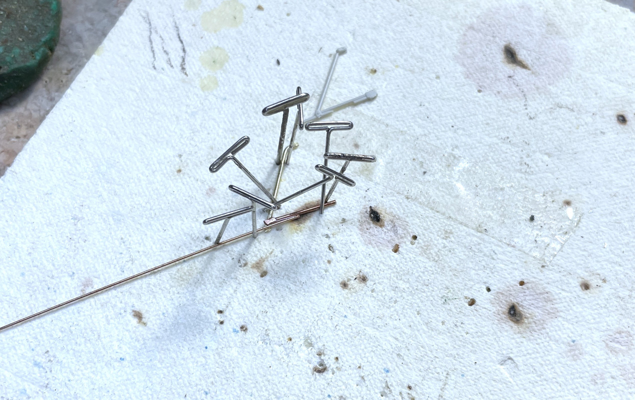
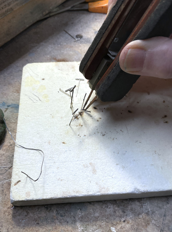
To do this effectively requires one more tool, my resistance soldering unit (RSU). This is not a cheap tool (actually my most expensive), but what it does is irreplaceable. It applies high current and low voltage between the tweezer electrodes that heats only the joint area controlled by a foot pedal. When the solder melts you release the pedal, but keep pressure on the tweezers to hold the joint together until the solder solidifies. I use 63/37 eutectic solder which goes from liquid to solder instantly with no slushy stage. It’s great for electronic work since the slushy stage creates a crystal structure that can be resistive (cold solder joint), but it’s also good for metal work since it solidifies so fast.
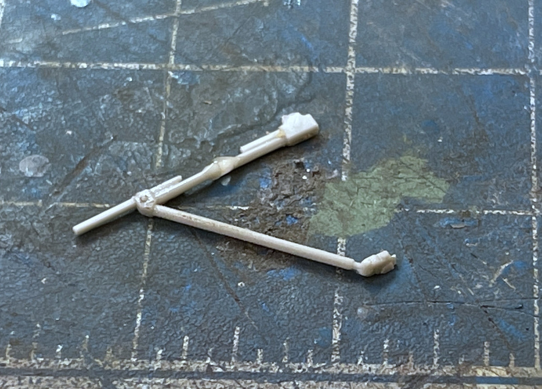
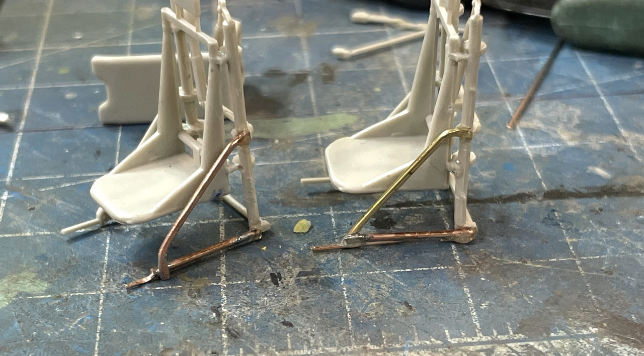
Here was the first one I did, but before I added the last thin part on the bottom. The wire is 0.032" and 0.022".
I bulked out the joint areas with some Bondic, but am not going to attempt to add any more detail to this part. The metal frame is held to the seat with gel CA.

And here’s the first complete seat with a plastic one on one side and the metal frame on the other. I have to make another one of these, since I broke two. I flatten the metal at the joint areas with a pliers and some pressure to increase the contact area.
When the seat is painted, the differences will not be too obvious. I suppost I could add a few drops of Bondic to simulate the fasteners at the junctions. Tomorrow, I’ll build the other one.
Remember: IT’S NOT WHETHER YOU SCREW UP, IT’S HOW YOU RECOVER THAT DETERNINES TRUE SUCCESS!"
Good recovery on the seat frame. Color on the rear compartment walls looks good. Nice job.
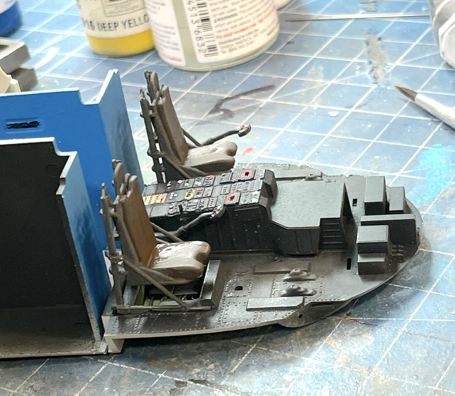
Thanks Gino! Got both seats fixed, painted and ready for final install. I painted more NATO black items that called out. The ResKit rotor head and tail rotor kits are now in my posession. The engine hasn’t arrived yet. I got more commission 3D printing jobs. The model club has dubbed me, “The Master Fabricator” and they’re taking advantage of it. Included in the batch of odd jobs are 1/72 handwheels for a 105mm cannon mounted in a M3 Priest, a set of 1/48 armored fuel caps, a 1/48 Pennsylvania RR station sign and a complete replacement pilot on both ends of a New Haven RR GE “Jet” electric passenger loco. The first pilot is coming off the machine in a couple of minutes. I’ll have to take it to the owner to see if it fits and if any corrections need to be made to the design. The orginals are Zamac white metal castings that have completely crystalized and crumbling. Taking measurements from them was very difficult.
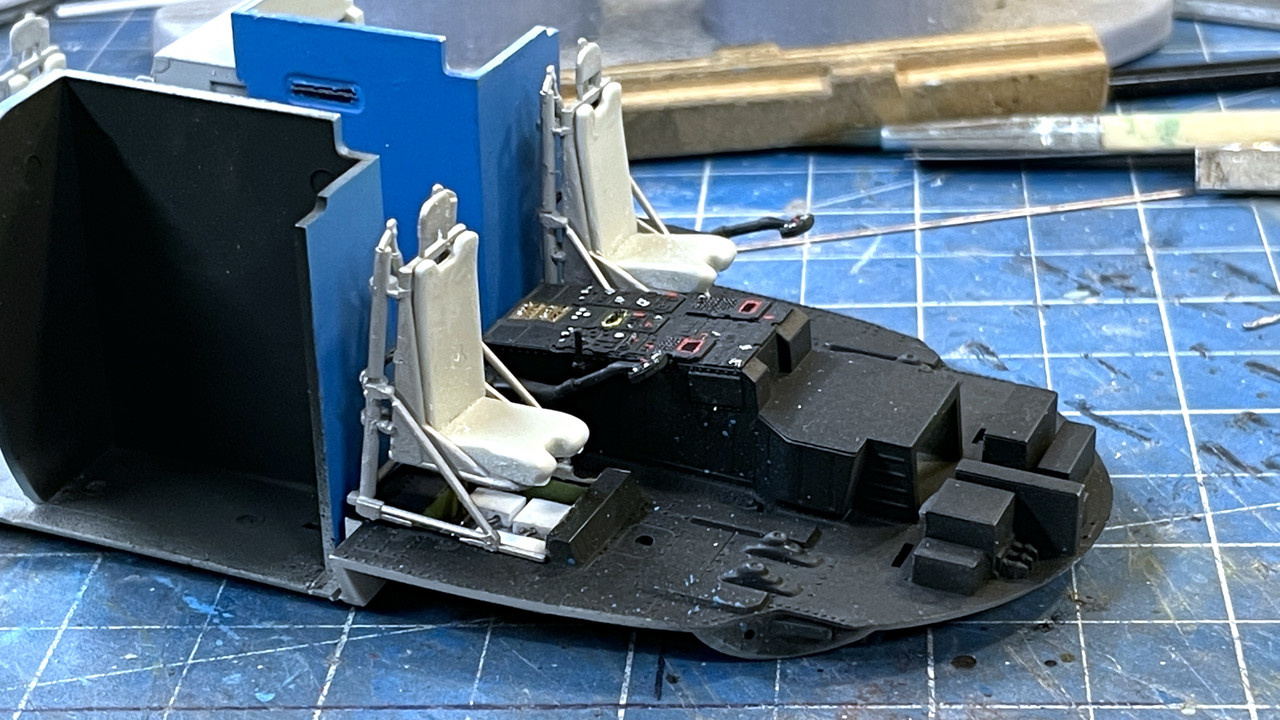
Onto the SH-60: Soldered another seat support system together and built both of the seats. Initially painted them the light gray, but then over-coated them with a mix of Allclad base aluminum with a little Allclad yellow aluminum. The real color is metal of some form or another, not paint. It’s paint in the passenger compartment, but not the cockpit.
I bit the bullet and decided to add some greeblies to the empty under-seat boxes. To facilitate getting stuff into them, I made some false floors out of some ABS sheet scrap. This way I can build the entire deal out of the model and put it in as an assembly.
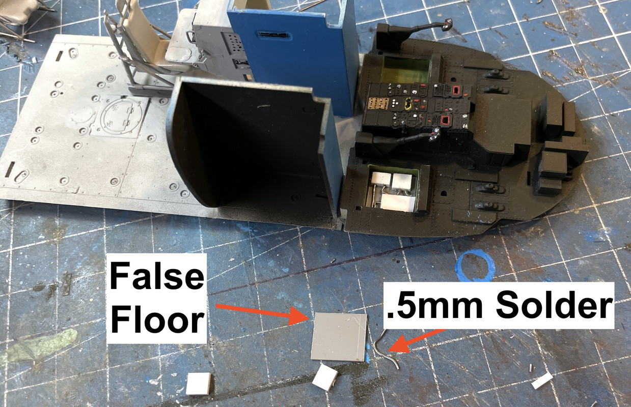
I’ll paint them off the model and glue them in complete. This image shows the seats with their new colored frames.
The inside of that chamber was supposed to be flat black, but there’s a skin over it that completely conceals it. Oh well…
Looking good. I do the compartments under the pilots’ seats the same way. As to the pilot seats, they too are black, seat pan, frame, and cushions.
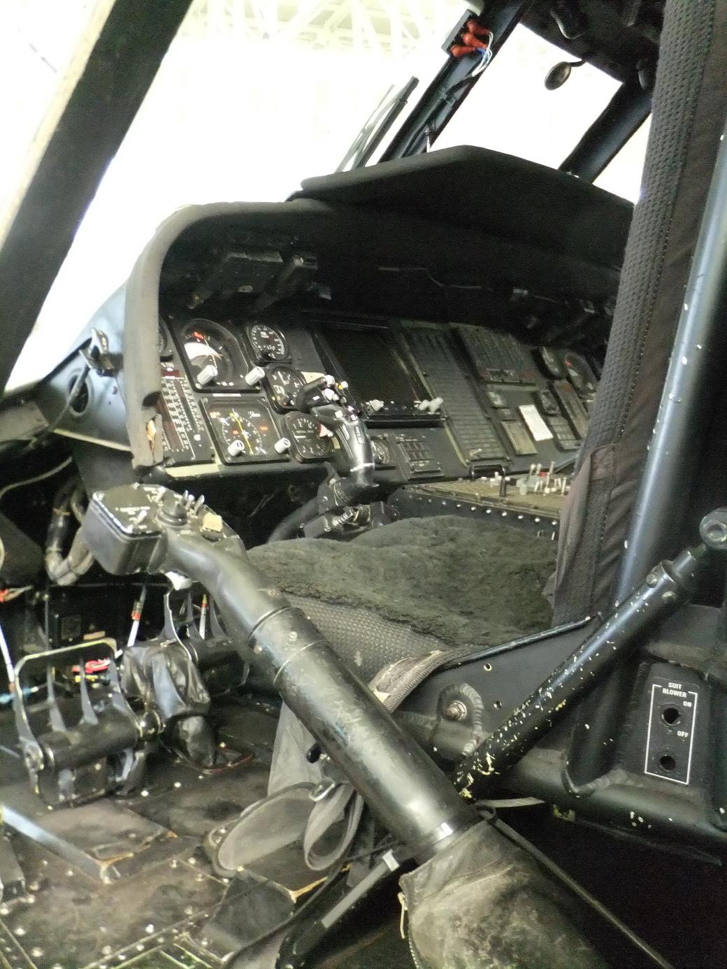
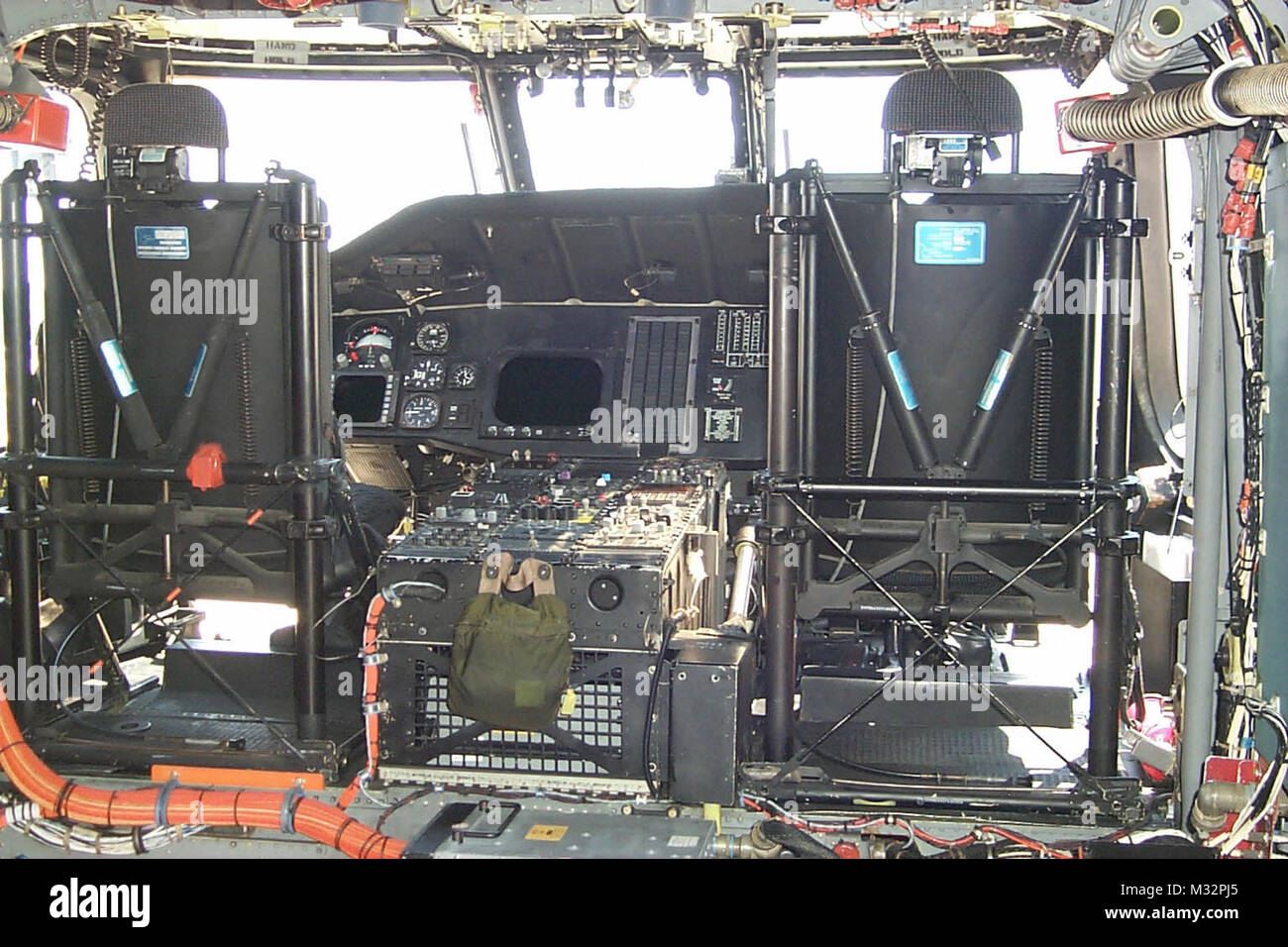
Thanks! I have a picture that shows a different frame color.
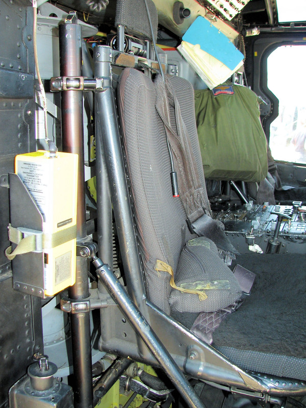
It’s really not black. Actually I’m not sure what color that is.
It looks like anodized black to me that has a lot of wear and rubs. If you look at the bottom rear of the seat pan where no one touches, it still looks flat black to me.

I corrected the seat color. Can’t have inaccuracies like that, can we?
I also finished the black boxes below the seats and dry-brushed some wear on the cockpit floor.
I painted the seat frames NATO black with a bit of flat aluminum. I then painted the seats Tamiya red brown with some NATO black. Seats are still not glued in since the seat paint was not dry.
I also finished two of the three 3d printing jobs. The loco pilot came out terrific and I’m hoping that it will fit. The other was a very quick and simple job to print PRR station signs.

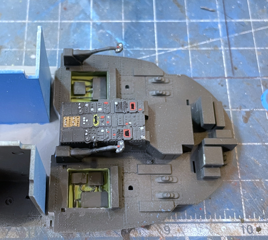
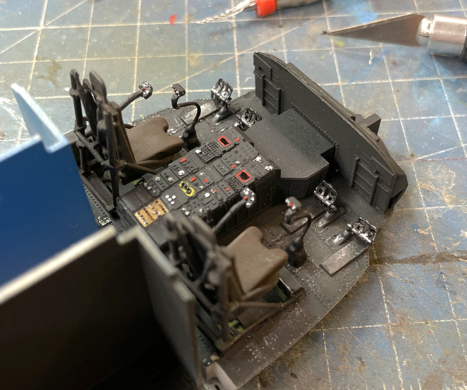
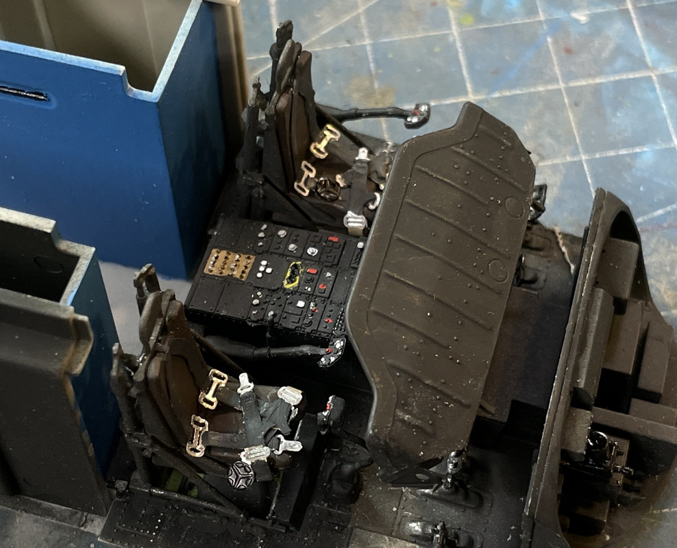
Had a nice long work session today and worked on several items at once. I’m continuing to work on the cabin and cockpit area. I installed the seats, sticks and pedals. There was a huge mold ejection stub that needed to removed on each pedals front side. The mounting point for the pedal was sorely under-designed. It was just a tiny little dimple. I drilled the dimples with 0.032" carbide bit. This gave the pedal some purchase and I glue them in with gel CA.
The sticks are painted with three kinds of black. NATO black for the grip area. Semi-gloss for the tubular part and rubber black for the boot at the bottom. I then picked out the buttons with a tooth pick to match the colors on my prototype pick.
Next up was the instrument panel. Like Gino, I decided to give the decal a try. When first laid on it was rather scary.

Before applying I put down a coat of Allclad water-based gloss. I painted the panel NATO black for decaling and it’s flat so the gloss was needed. I really didn’t have to paint it at all. I also applied some Micro-Sol to the gloss. After application I coated it with Micro-set, and did this at least three times.
This image was an intermediate shot with about two applications of setting solution.

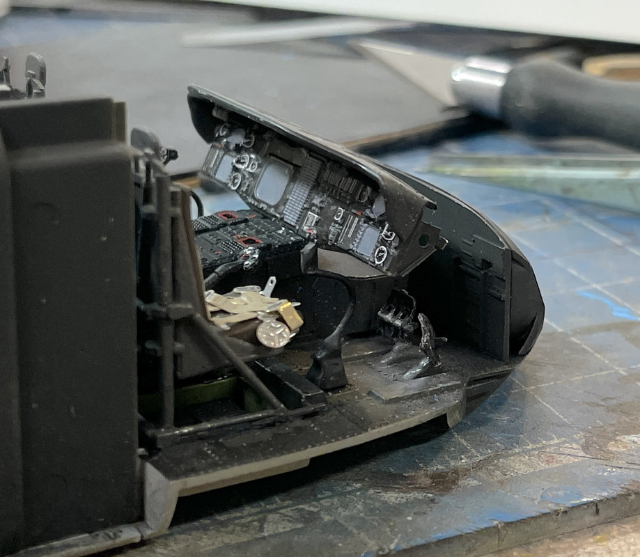
I went back and poked some holes and slices in areas that really needed some more help. And here’s what it looks like now. It’s snugged down pretty well, but I really don’t like how the dial gauges distorted.
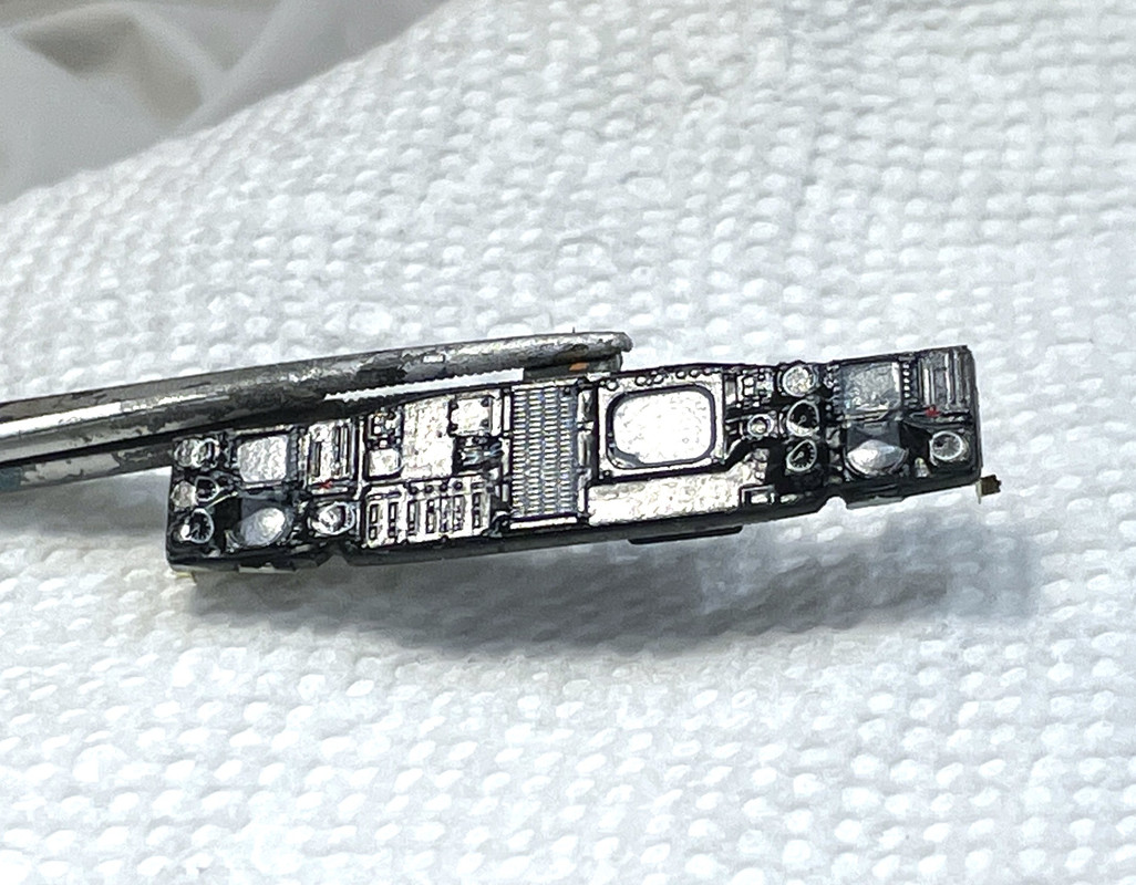
I will go back and selectively apply matte finish to everything except the CRT and guage faces. I might have been better to scrape all the raised details off before applying the decal. Oh well…
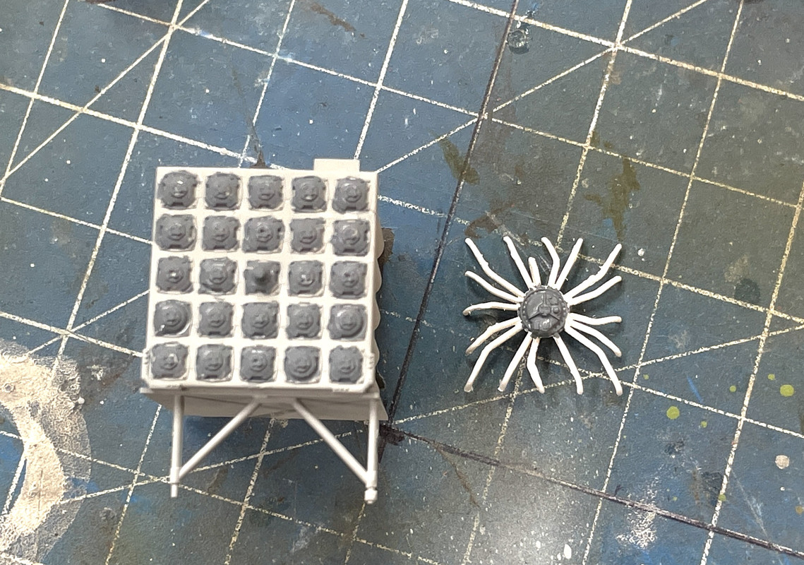
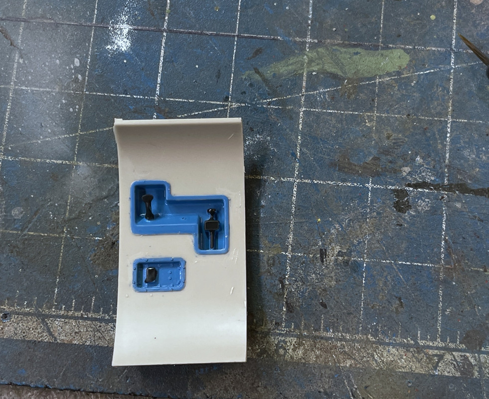
Next up was the sonar module. I have a great picture of it so I was able to match the coloration closely. The piece glues into the model at this stage by just two legs of the stand. It’s a very dubious connection.
And then this happened!

While I could have drilled the broken halves with a 0.010" drill and pinned it with guitar string steel, but I chose, instead, to build another wire assmbly. Once I found out how quickly I could cobble these together with the RSU, I just got to work and did this.
After trimming to match the old stand, I CA’d the sonar assembly into some re-drilled holes in the floor.
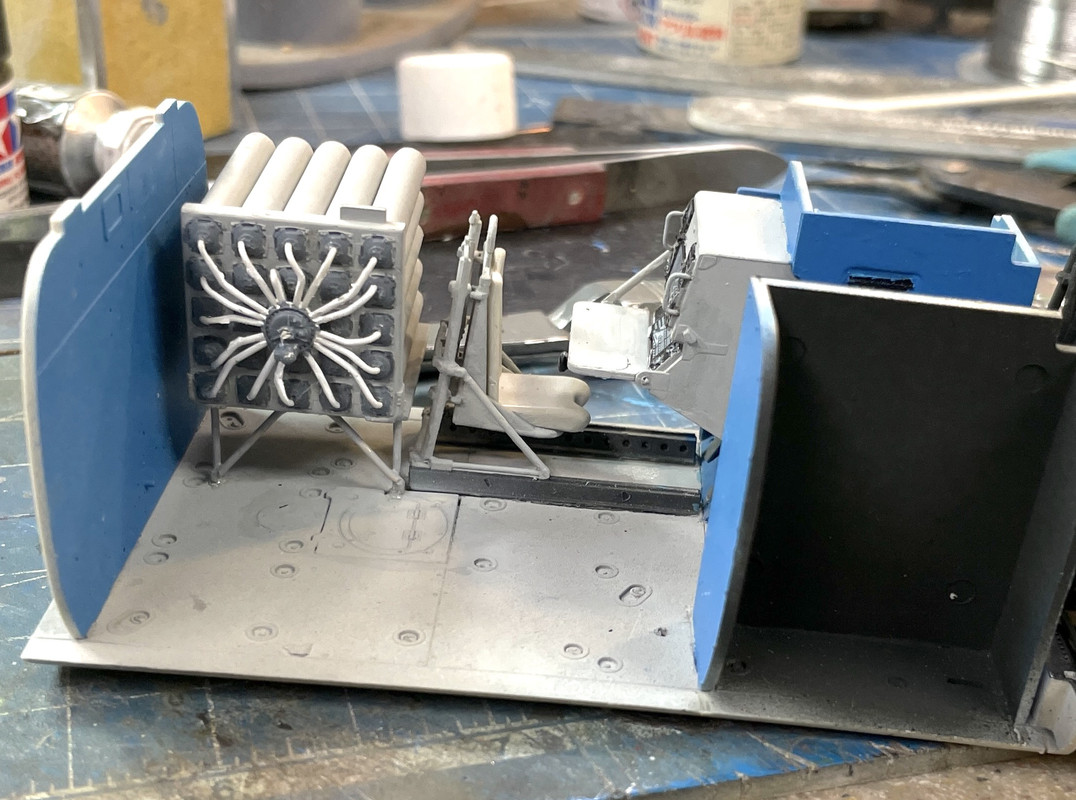
Once again, dodged a bullet.
See y’all tomorrow…
Coming along nicely.
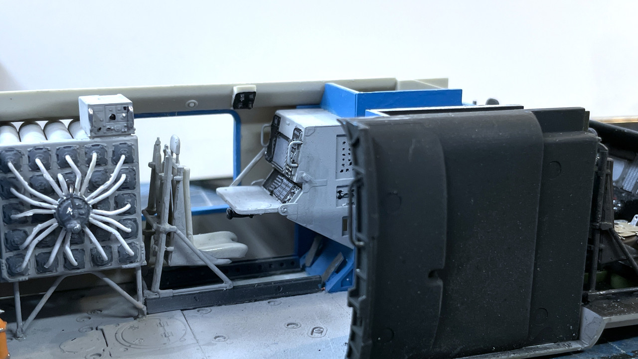
Moving ahead on the interior. I used some clear flat on the non-gauge areas of the instrument panel and built the assembly and installed it. I added two more interior/exterior walls after painting the blue trim around the window next to the sonar station. I added some more small details which sometimes cause more stress than they’re worth. I then went to the hobby shop to drop off the commission work I was doing including 3D printing some very small 1/72, 105mm Howitzer hand wheels. They were the smallest parts I ever printed.
Other than the “warped” “steam gauges”, I agree with Gino that the decal looks okay.
This was one of those small parts that should have been a breeze to put in, but it wasn’t going in. I then found that there was one of those ejection pin huge pieces sticking out on the bottom keeping it from settling in. Once i removed it, things went better.
Gino informed me on another forum that the seat belts are black with the circular lock black also. The clasps are silver. I’ll attempt to make that change today.
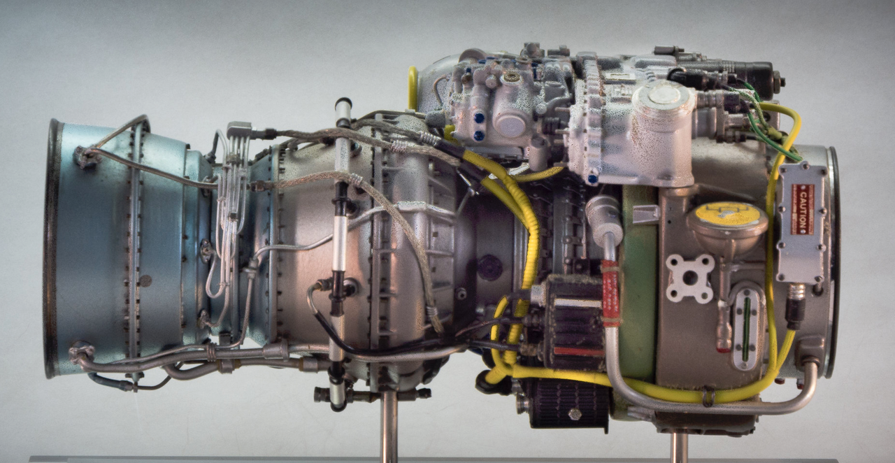
Picked up the remaining ResKit parts at the hobby shop. I was very pleased with the engine kit where it calls out in detail all the piping that makes turbine engines so interesting. I now have four more complicated sub-kits: Main Rotor, Tail Rotor, Rt T700 Engine and the articulated tail joint.
I changed the seat belt color to comply with the images Gino posted.
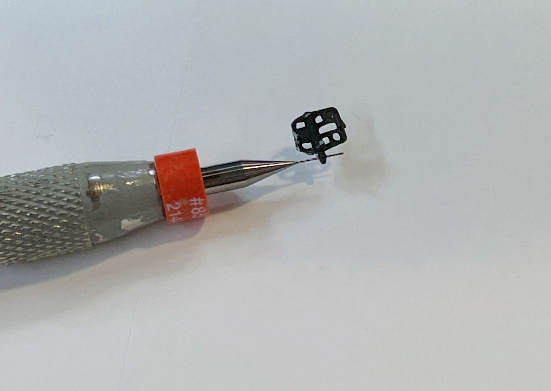
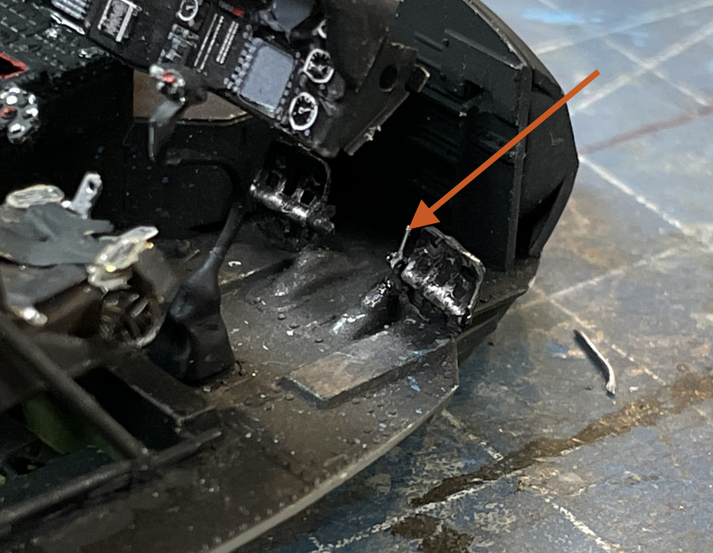
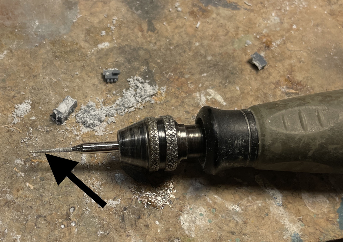
While doing this I must have put some pressure on the right rudder pedal on the co-pilot’s side and broke the tiny plastic pin holding it to the base. I drilled the pedal and base with the 0.010" drill for some High-E Guitar String. Here’s what that ridiculously small drill looks like. They’re so brittle and fragile that it’s quite easy to break them taking them out of their little holder box, or if you exert any side pressure at all.
I re-installed the pedal with the wire, but it’s a little long. I’m leaving it as it is.
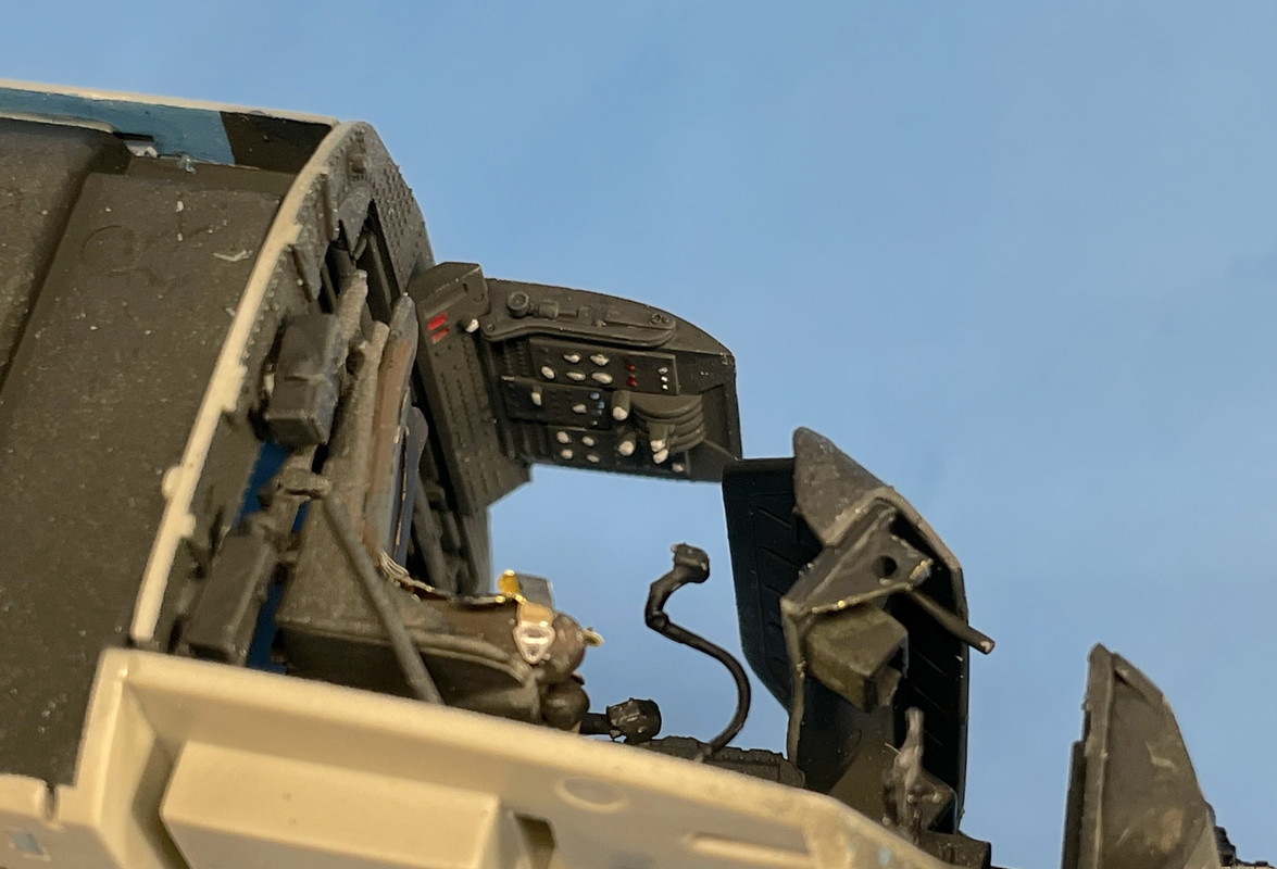
It was time to finish the interior starting with the cockpit end bulkhead and some other appurtenances along with the overhead control panel. It seems like the trottle controls are overhead.
I then went an painted all the controls. There’s a decal for this, but there’s so much raised detail that I felt hand painting was okay.
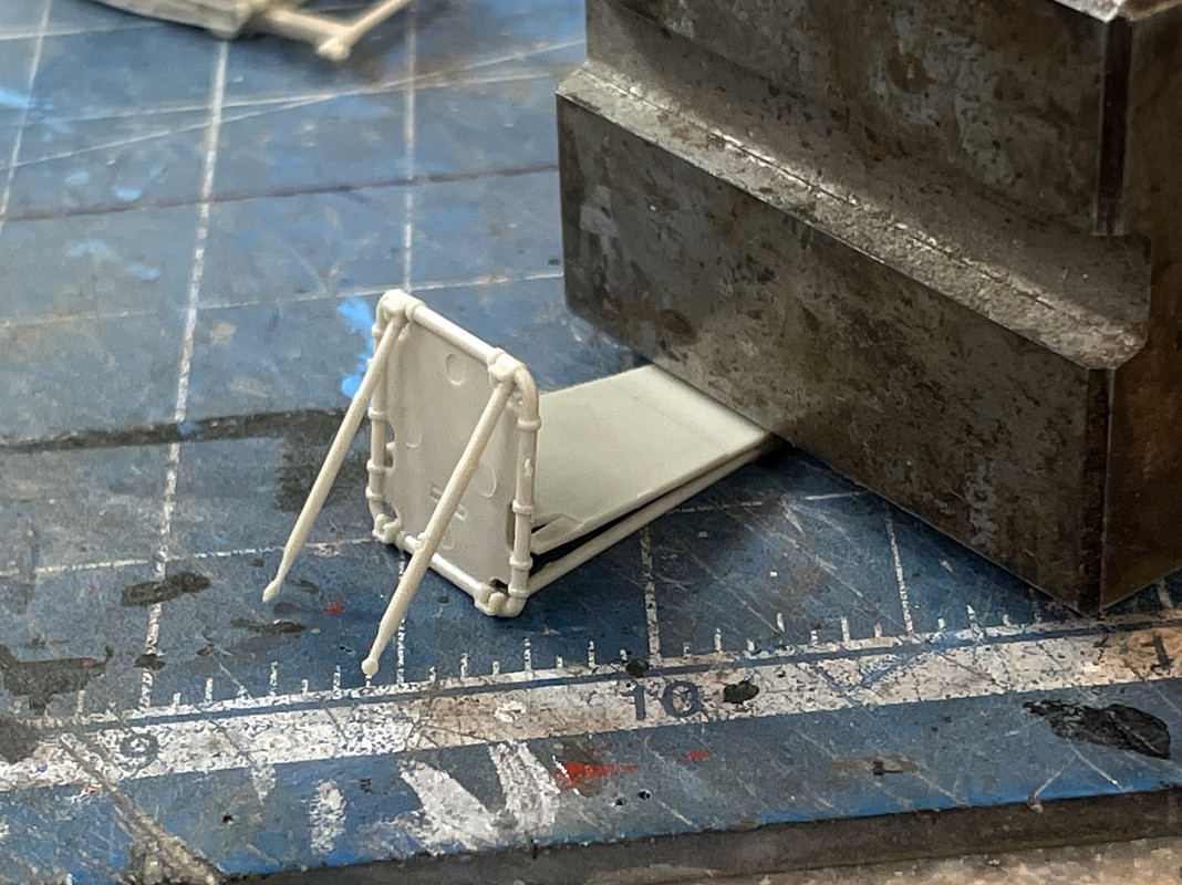
There were two more seats that needed construction. As I noted before, I’m not happy with the engineering of these seats. They’re attempting to make scale-sized members, but that gives no gluing surface and some of the cross-sections can’t sustain themselves.
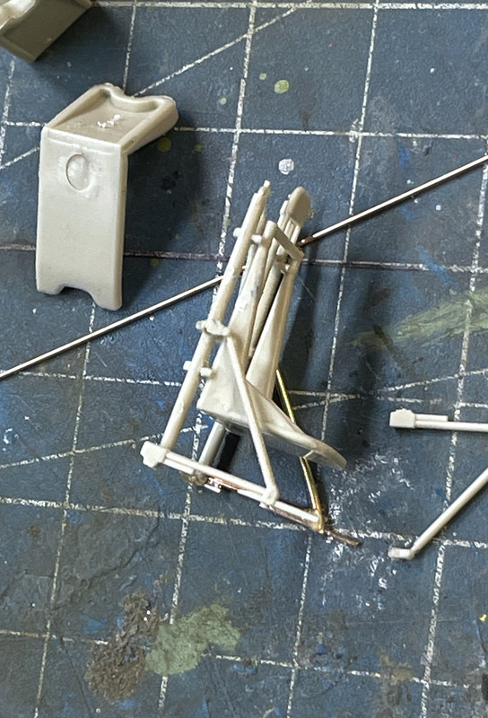
A perfect example is the ceiling supports that literally hold this seat into the aircraft cabin. The plastic narrows down to probably less than 0.020" and I broke two before I got one built and even then it broke when I glued it into the ceiling.
To hold it steady I sat a steel angle block on it.
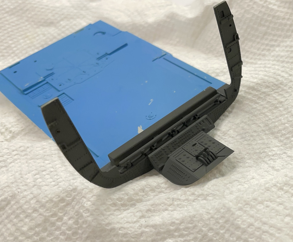
As it is I now see that it shifted on the wall mount when I used med CA to hold it in place. Notice the pressurized gas cylinder that I piped into the Sonabuoy launcher.
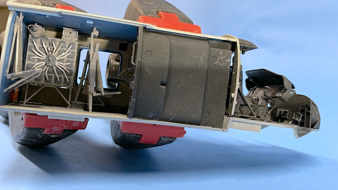
But as you’lll see, the extrerioir wall completely hides this seat so no harm no foul.
That’s not glued in yet. I did do some trim painting on the other side, which also is impossible to view. You can just see it looking in the window on the opposite side of the cabin. Haven’t seen images of this wall and really don’t know what the coloration, but it isn’t visible.
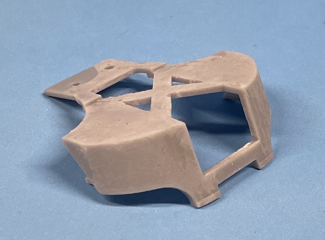
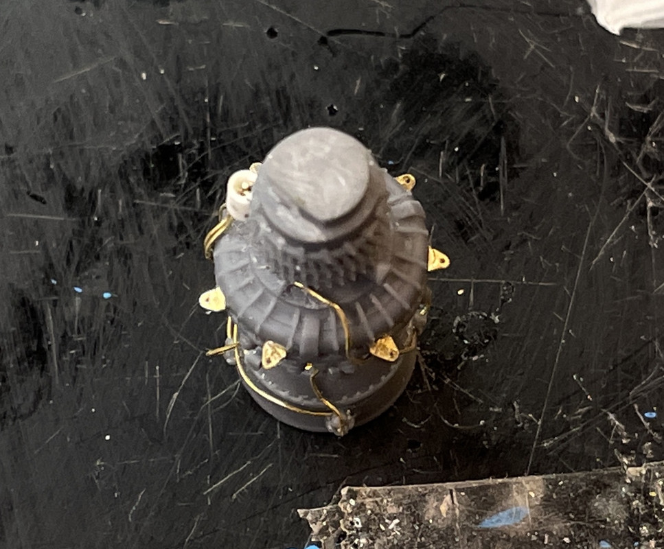
Today began the building of the ResKit T700 turbomachinery. As much as I was looking forward to this, the build is going to be very challenging for me. They want you to put in all this piping, but you have drill all the holes yourself. That’s that dastardly 0.010" carbide drill. I broke three and still have a lot more holes to drill. They’re $1.75 each so those are some expensive holes, but there’s really no other way to create .3mm holes in resin without drilling them, or so it seems to me. I was happy that I was able to remove the sprue block without difficulty starting with the Dremel Flexi-shaft and a pointy diamond coated burr. It beat trying to finagle using some saw or another to do it.
I started using some 0.010" brass wire, and you’ll see how it worked. I then started using piano wire (High-E guitar string). It’s really tough material and if you bend it wrongly, you’re screwed, but it holds it shape very well. You cannot cut this with normal sprue cutters. The steel is harder than the jaws and will leave nice half-moon grooves in the cutters. You must use hard wire cutters.
I drilled a test hole and tried out the brass wire. If fit nicely.
I started laying in piping based on the instructions. The instructiions show four pipes going to a small block on the left side. There was no way to drill that at all, let alone put four small holes or one large one. Insteaad, I milled a slot down the middle using the burr. Even with that, getting three lines terminated there was sub-optimal. I ended up building the block up with some Bondic. I reshape that when all the lines are there.
When I could drill holes for the piping I did. There was a very fine pair of PE pieces function of which I have no idea, that went into a tiny groove around the circumferance. It’s a very thin PE and I continually kept bending these little protrusion over. I found one that already broke off. If all broke off I don’t think anyone will miss it.
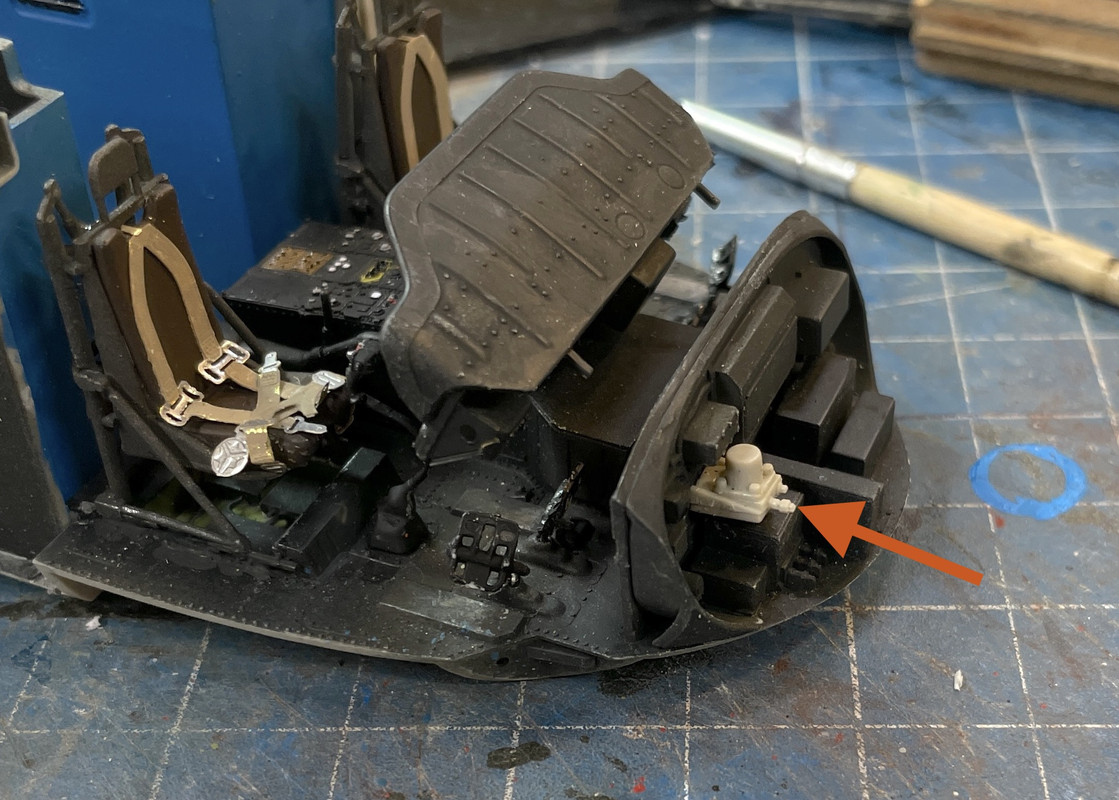
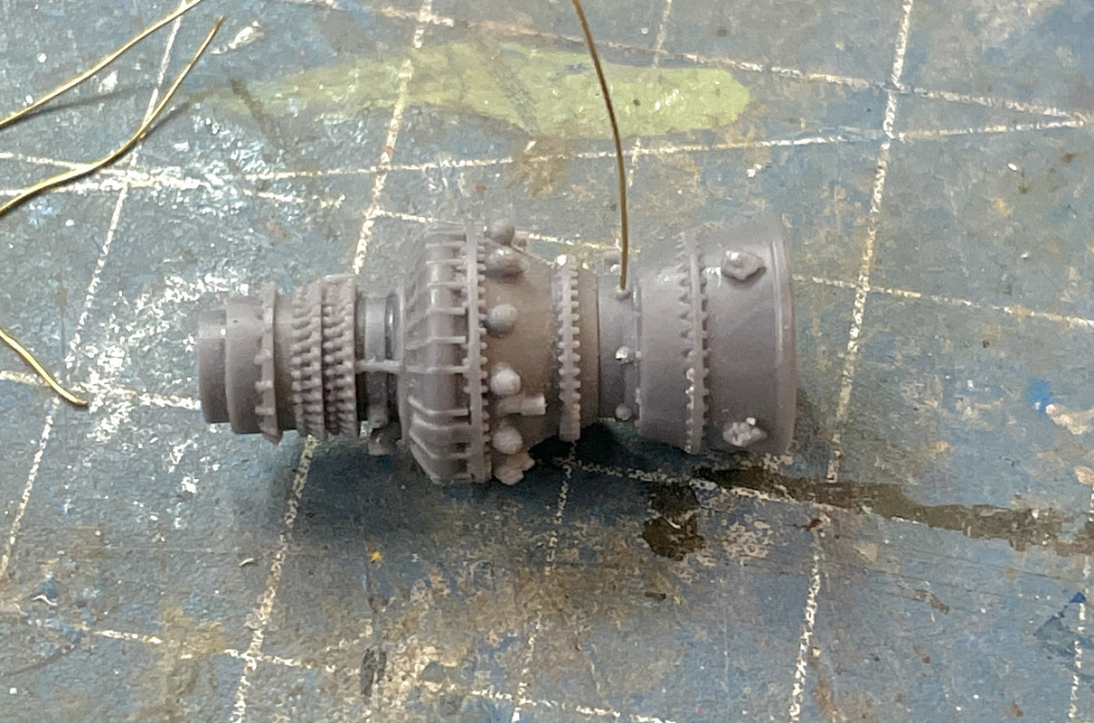
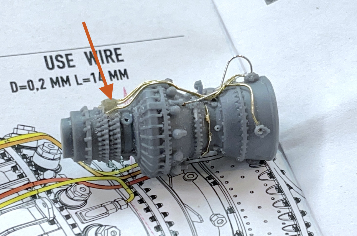
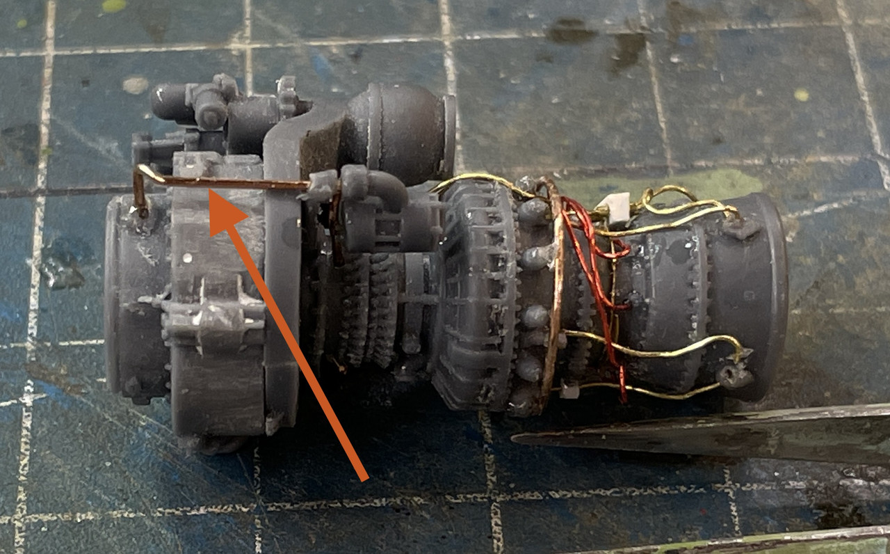
And here’s where I left it tonight. As you can see I started using the piano wire on some of the piping. I think the curves are too high, and it’s not exactly the way it supposed to look. There’s a lot more piping that needs to go on. These engines are advanced models all to themselves. The arrow points to the Bondic expanded block.
Tomorrow work will continue.
Nice job on the engine so far.
Glad you like it, but there were things I didn’t like (and still some more). First of all, here’s a shot of the instructions showing some of the challenges.
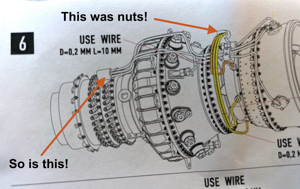
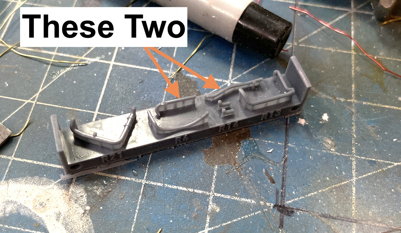
With the gauge wire I’m using there was no way to stuff three or four pipes into the tiny resin aspects that they’re telling you to do. After my futile attempts to grind them and smash the wiring into them with Bondic resin, I decided to eliminate them and redo them, albeit larger.
The cylinder on the left was a molded part, and the bracket on the right was actually an added part. There were no holes or slots in either and putting them in was nearly impossible.
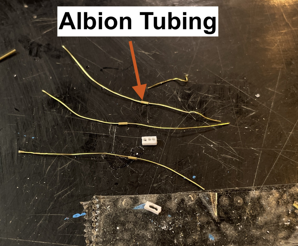
To facilitate threading the piping through the new blocks I used some Albion micro-brass tubing. Here’s the tubing slide onto the brass wire. BTW: the source of the brass wire was a woven nest around the bottle of some Italian or Spanish wine. Wine bottles are a great source of modeling supplies including the foils that wrap their tops. And they have the added benefit of providing pleasure. It’s a win-win!
This image also shows the three holes drilled to accept the tubing. I made a silly mistake. I thought I was drilling them with the correct 0.020" carbide drill, but had a 0.032" drill, so the holes were oversize. Later I realized my mistake and used the correct size. In the foreground is a reject block where the holes joined together.
Here’s the information on the Albion Tubing. Chuck Wallace uses this in his super-detailing work and I really like it. I cut it with a new single-edged razor with the tubing thread over a piece of High-E guitar string. This captivates the little buggers which are prone to go into the ether with the slightest provocation. Use a hard wire to hold the cut pieces. If you use brass, the wire will cut along with the tubing and create a problem you don’t need. You don’t have to press too hard. Look at the reflection of the tubing in the razor as you roll it back and forth. Keep the reflection pointing straight back as if it were the same piece to ensure your cutting squarely and not cutting a spiral.
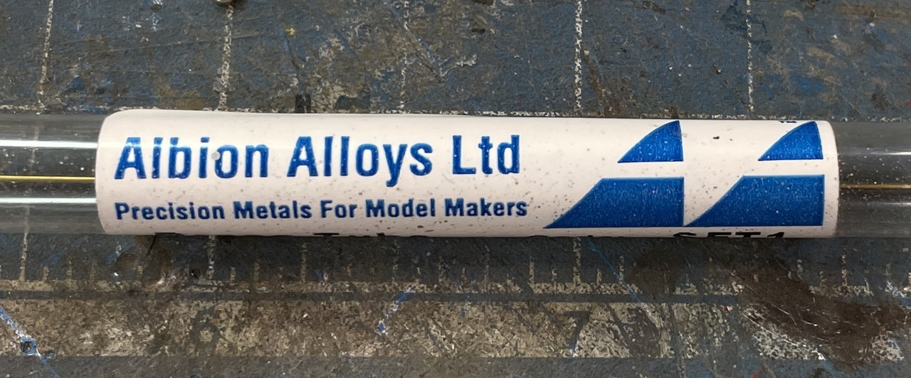
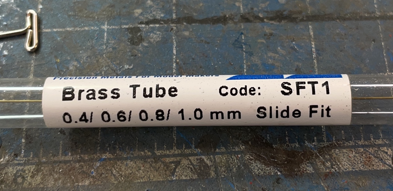
I believe for this application I’m using the .6mm tubing.
For the rear teminus, I drilled a piece of 3/64 Evergreen styrene. Four pipes go into this. I don’t know how ResKit expects the builder to terminate the wire without holes to go into. I am sensitive that these blocks are about 2X oversize, but I really couldn’t deal with them any smaller.
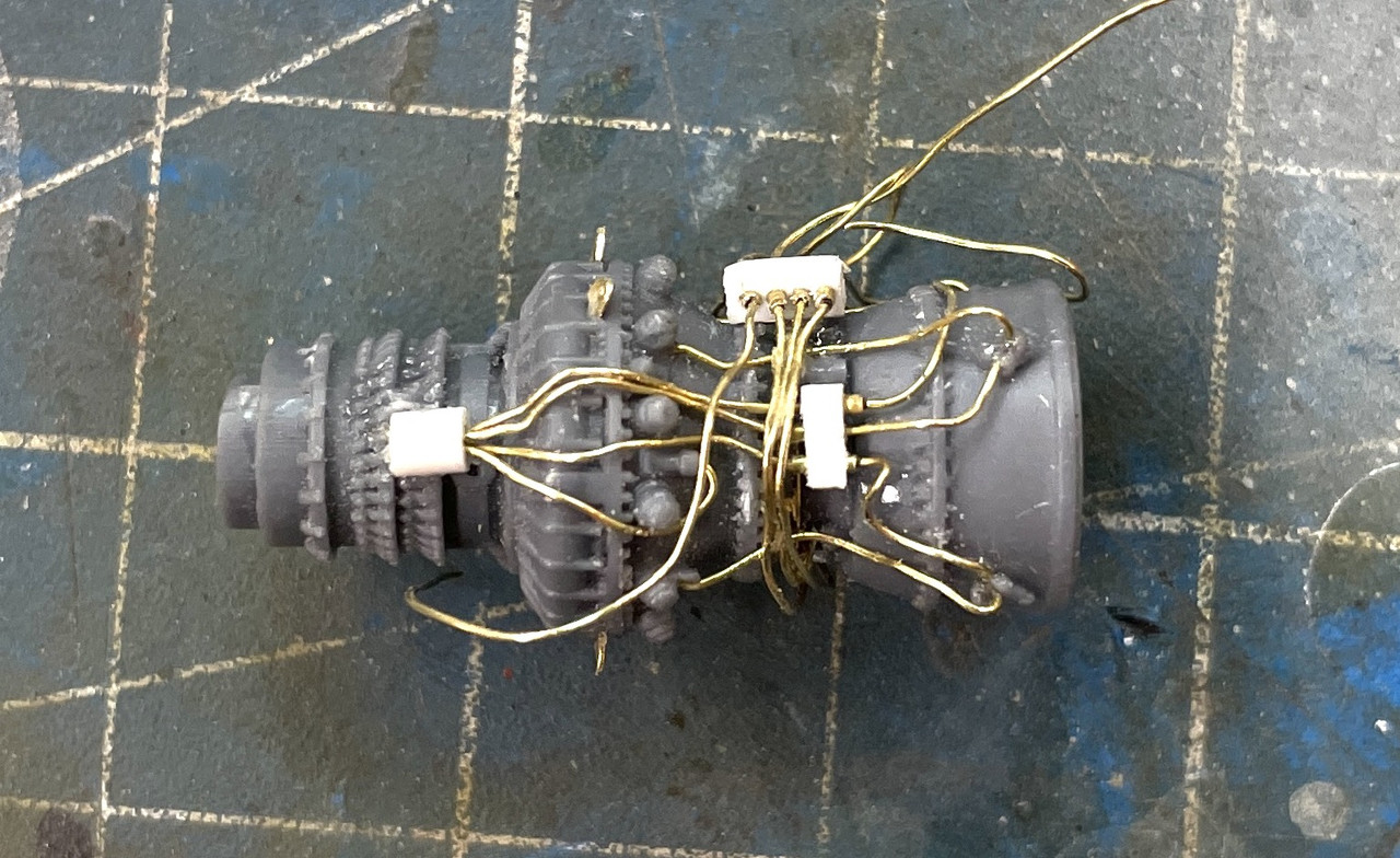
I really didn’t like how the piano wire was laying. The loops were too large AND I couldn’t bend them much tighter. That stuff is really tough.
The fact that they’re already nice and shiny didn’t matter since the entire engine’s going to be painted including the piping.
So I pulled them all out and substitiuted them with the brass of the same gauge.
And the reverse view. You see another small block that substituted for a tiny bump through which that pipe was supposed to pass. Really?!
More crazy PE had to go on. I lost a few of these. What made it worse, when removed from the fret, they were to wide at the base so I have to clip their corners with a #11 blade, and that was particularly not fun!
Some of this detail is nonesense at this scale. I would like it better if it were 1/32 or even better at 1/24. It is astonishing to me that a turbine can produce 1,900 hp and weigh less than 500 pounds. They’re really quite small.
Another set of pipes goes around the perimeter from points in the circumference and then through that bracket. I removed the kit part and substituted another drilled block supported on a piece of Phos-bronze wire. The kit calls out .2mm wire for this run and I’m using the equivalent of .3mm. I think I have some magnet wire that has a smaller diameter and could replace this too. The piping is not too hard to rip out and fix.
Getting that brass to lay nicely is like herding cats!
That’s brings us up to date. See y’all on Monday!
Happy Monday!
My wife and I have a deal that I don’t work in the shop on weekends, so for me, Monday is actually a pretty happy day.
I literally spent hours doing a very few things. This is bordering on watchmaking or creating Fabergé eggs. I found that that my magnet wire is a few thou smaller in diameter than the brass wire so I replaced Friday’s harness. It’s a bit better. It’s still a little larger gauge (2.4mm vs. 2mm) than specified in the instructions.
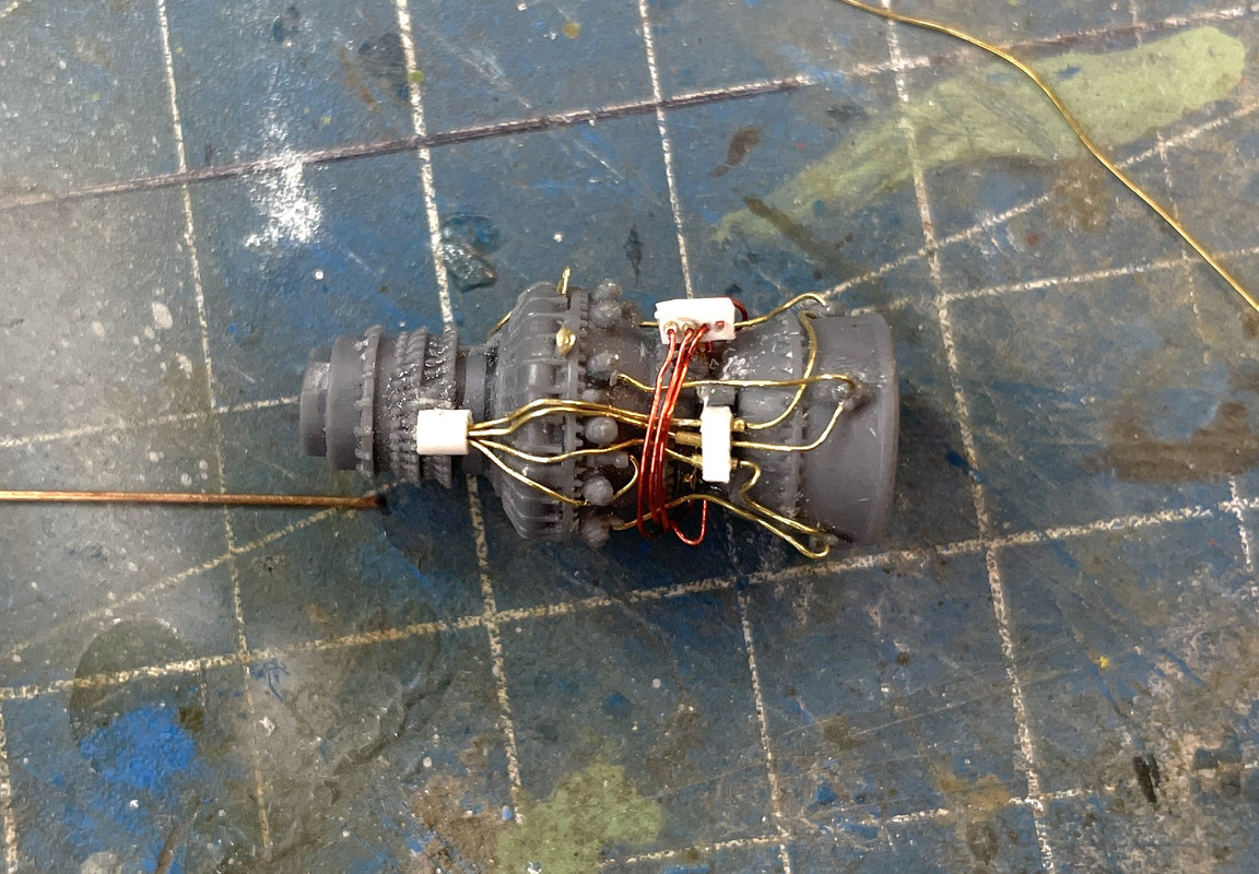
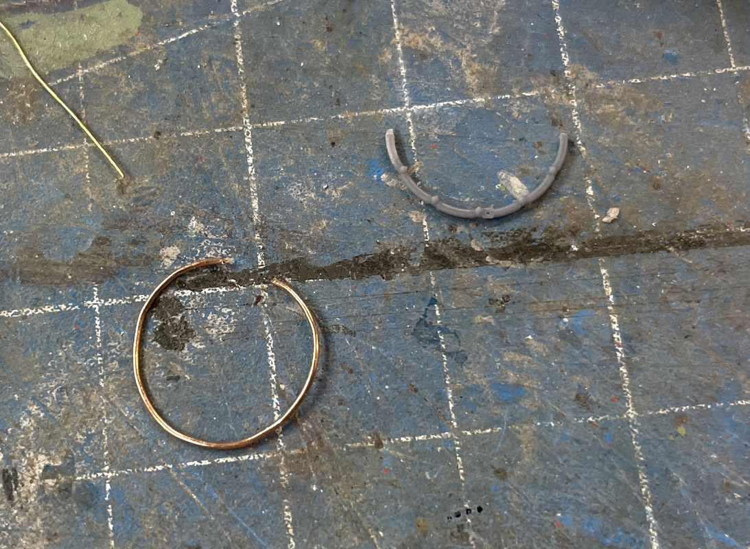
Next up. There was a ridiculously fragile resin ring that is the fuel manifold (I presume). It broke two times and I gave up on it. Some things are best not cast in resin. There’s also a bunch of piping that is going to be replaced one-by-one as I get to them. If you can get them off the casting block you’re still left with the challenge of re-shaping them so they’re round.
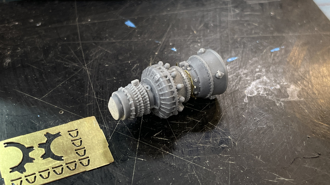
I made a new ring out of 0.022" phos-bronze. It wasn’t fully rounded yet in this image.
I placed the engine in my PanaVise to stabilize it while I glued the new ring in place touching each of the fuel injector sites.
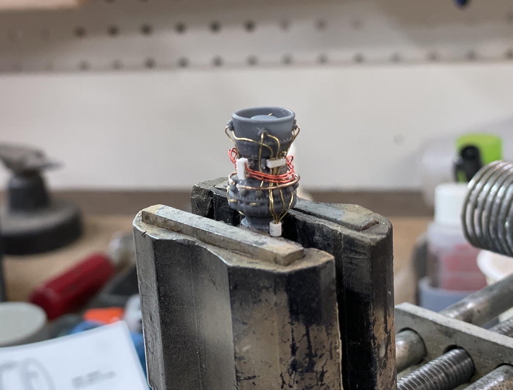
The accessory drive was comprised of three castings. They’re fragile and exemplified by my breaking one in half. There are some alignment pins on some of the parts. Unfortunately they don’t fit their corresponding holes. I ended up sanding them off.
Gonna be a lot of fun painting all these details.
There was another very small/fragile cast pipe array that held a pump in place. The pump DOES NOT actually glue to the gear box, but instead, is completely held in space by two pipes; this elaborate longer one, and a very tiny insignicant small one. My first attempt was to use the resin long pipe. Notice I used some Phos-bronze wire to replace the almost-non-existent resin locating pin. The other pipe was a tiny resin elbow that I also replaced with metal.
The longer pipe broke so I replace it too. I left the 90° part which had the fitting.
There were some electrical boxes that went on next. Working on styrene kits is much more predictable since many of these pieces went into approximate locations. Here’s the diamond burr I use to remove resin parts from their sprue blocks. It gives great control, much better than using a blade or razor saw.
But wait! There’s more! There was this wiring harness as laid out in the instructions.
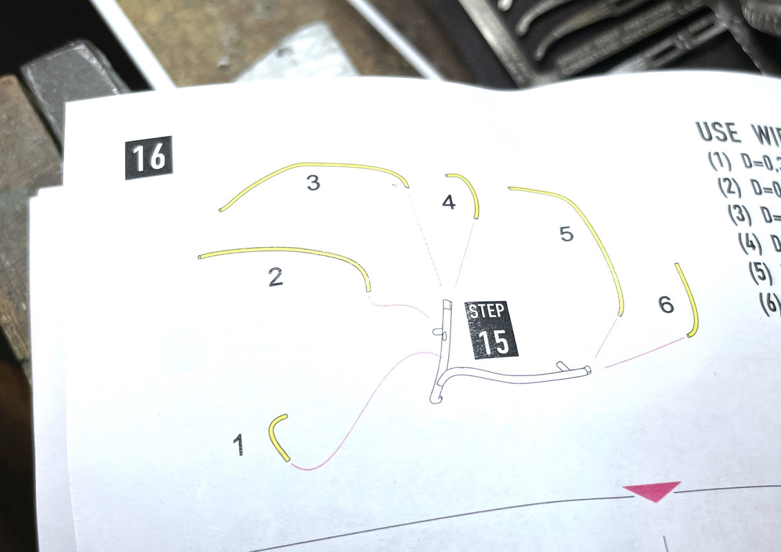
In a previous step they had you glue together the two resin branches. Yeah! Like that was gonna happen? They’re actually telling you that brass wire should connect some how to the various points of this resin assembly.
Here’s how those parta looked on the sprue block.
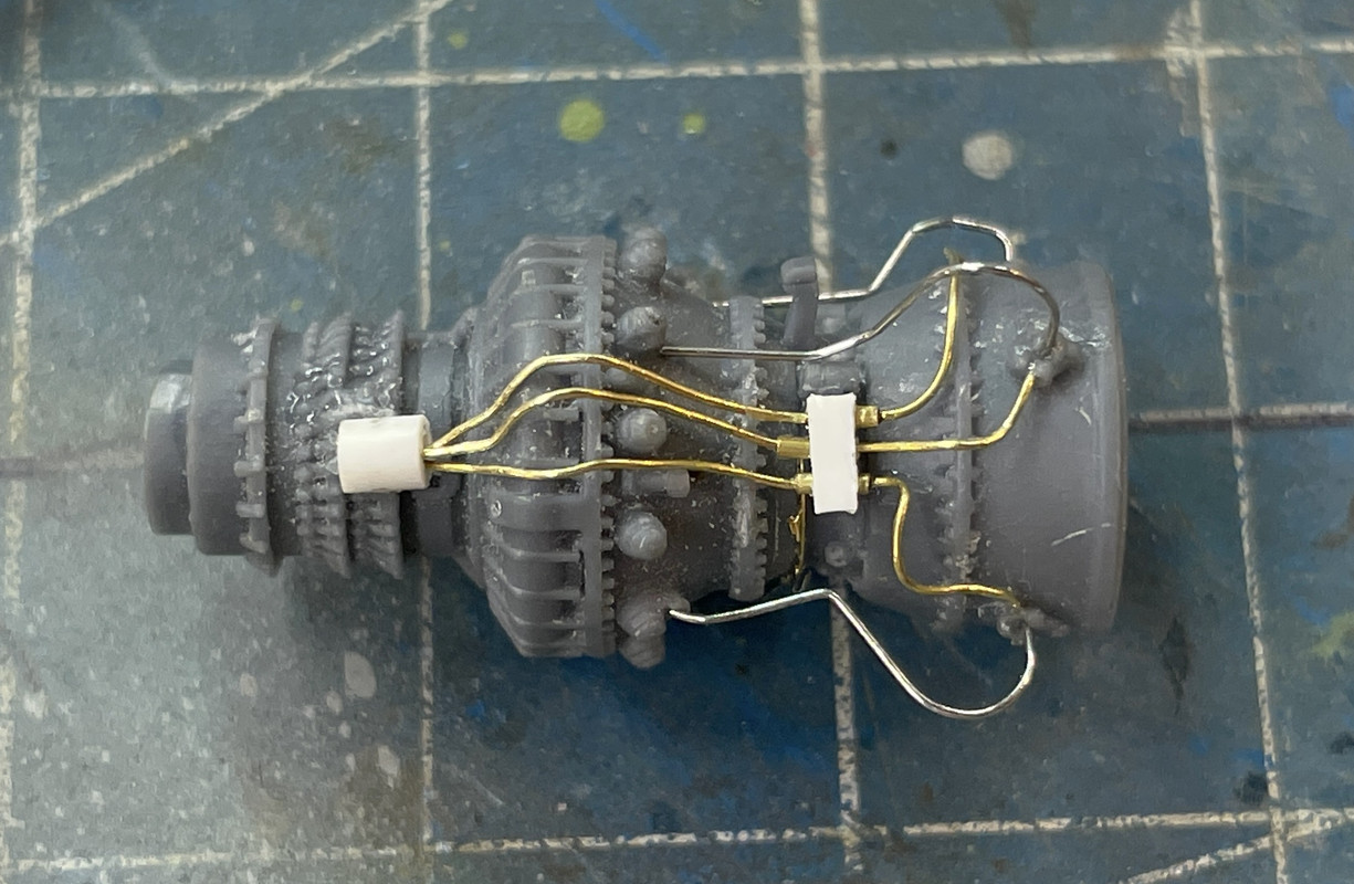
I didn’t even attempt to use them. Instead I first tried to use some 28 gauge wire sheathing with the correct number of pipes as shown, but this wasted 1/2 hour of my time and produced basically nada. I then decided to go a little over-scale and use shrink tubing. This is on the aircraft side of the engine and probably won’t be visible with the open cover on the model. It was much easier to use the shrink tubing. I didn’t get all the terminations done by quitting time. I suppose I could use some small brass tubing to do this. I will think about it… This is a bit clunky! The beauty of scratch-building is I can do it over and over until I get it right.
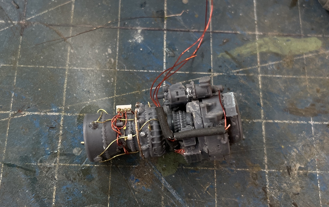
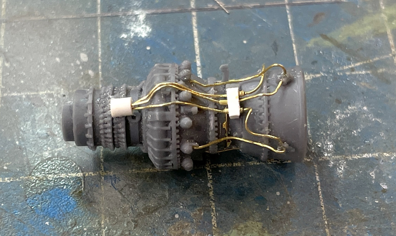
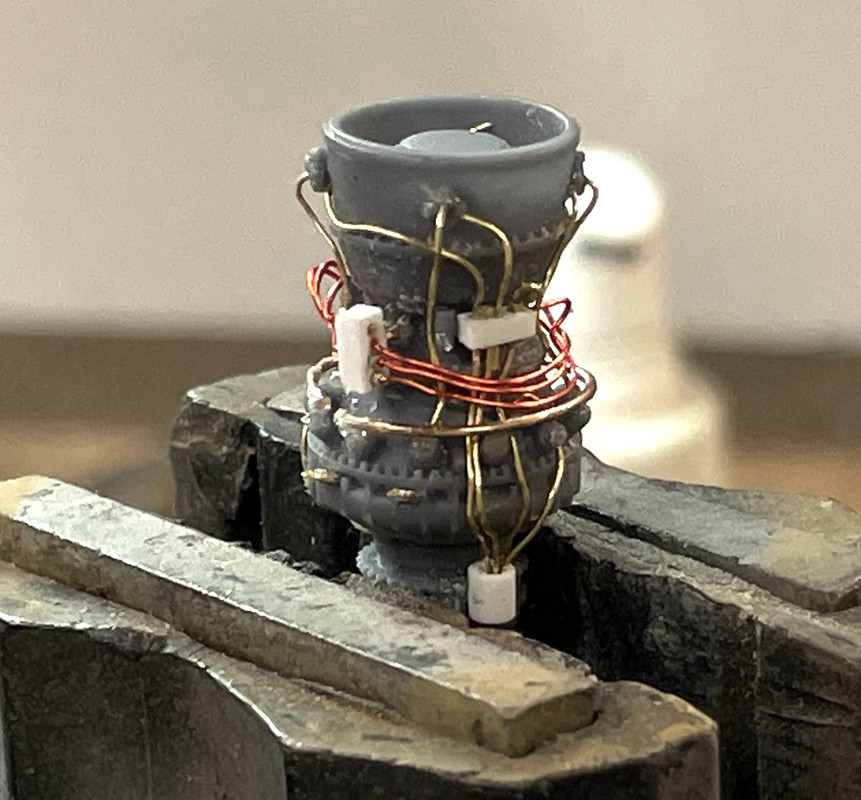
Short session today. I am now declaring that the piping of this baby is done. Some of the piping isn’t… it’s wiring. In fact, that thing I struggled with the last piece yesterday is actually a wiring harness that’s just wrapped with yellow tape in the prototype. I actually thought about ways to recreate this effect then dropped the entire idea when I reminded myself that this is on the back side of the engine and won’t be seen by anyone excpet, me, the creator.
Creating that wrapped harness in 1:35 would be an interesting challenge, but I’m not going there because of my above rationalization. There’s lots of different colors in this little model.
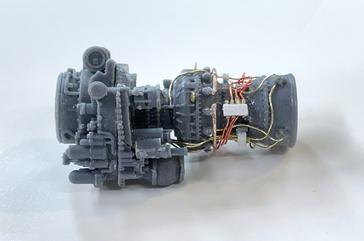
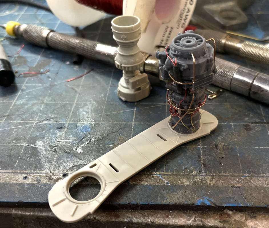
Here’s my final rendition before I finish the last little bits (engine mounts).
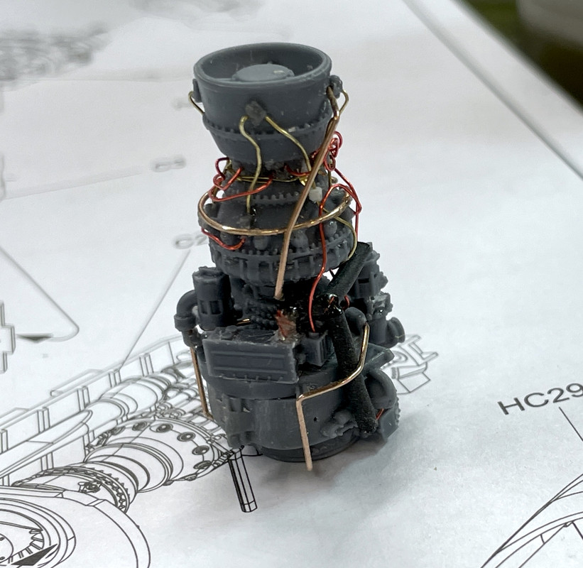
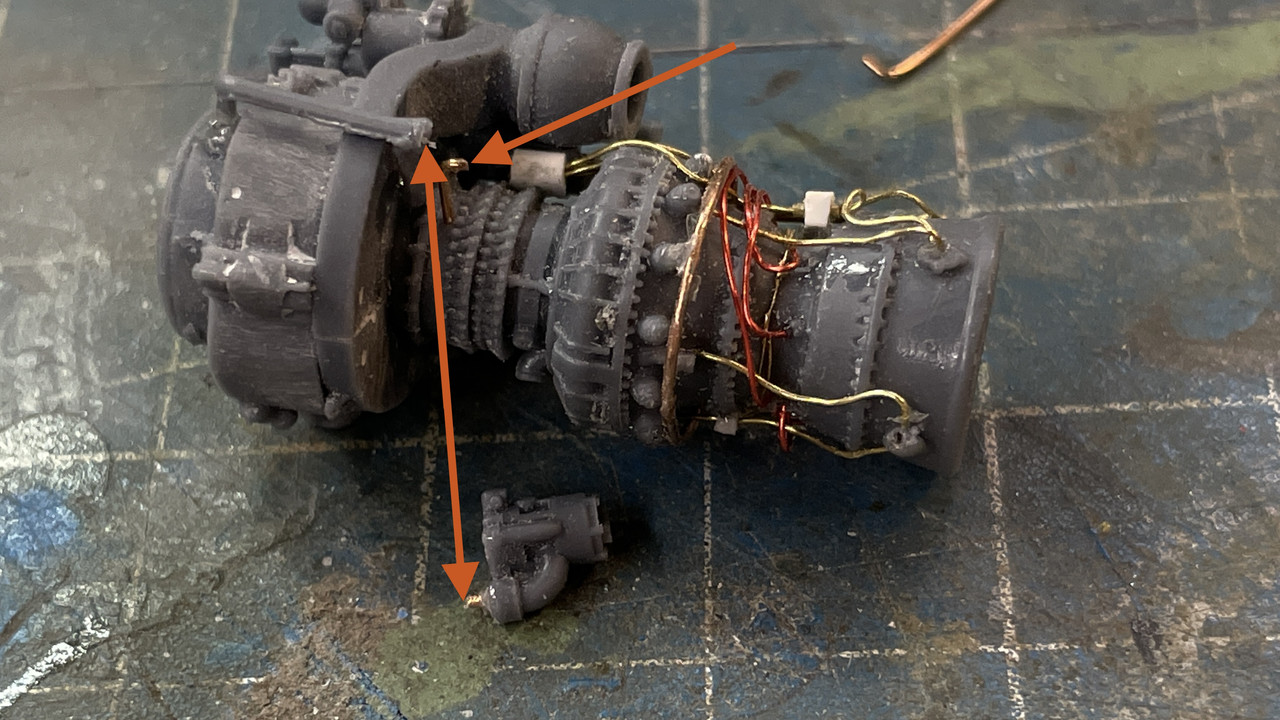
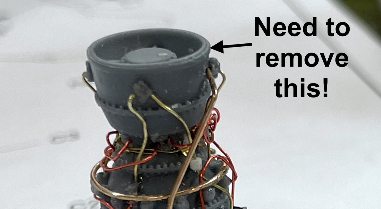
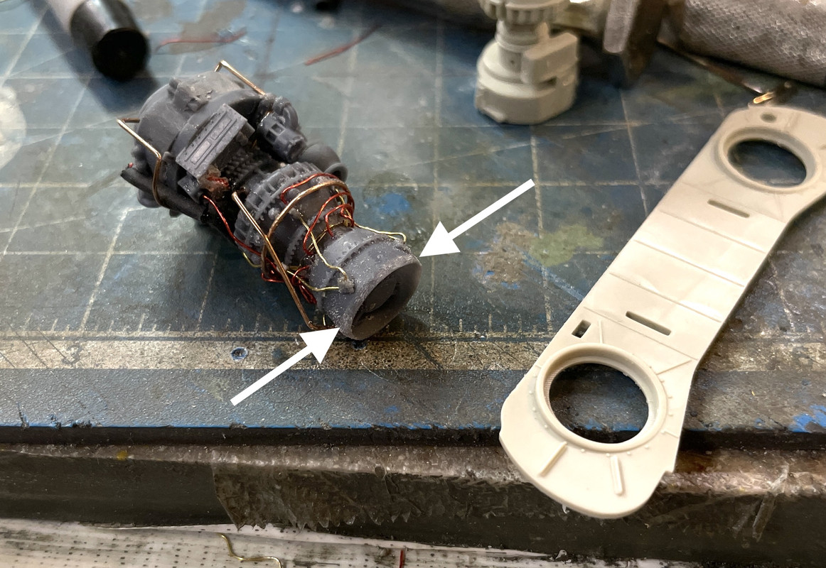
I tried the model out in the plastic kit part that captures the engine on both ends. On the exhaust end it’s okay, but on the intake end I have to remove the nice flange that surrounds the intake bell as pointed out by the arrow.
This whole build is very entertaining and inspirational.
Keep up the wonderful work.
Ben
Glad you’re enjoying it. It’s been mostly fun for me too.
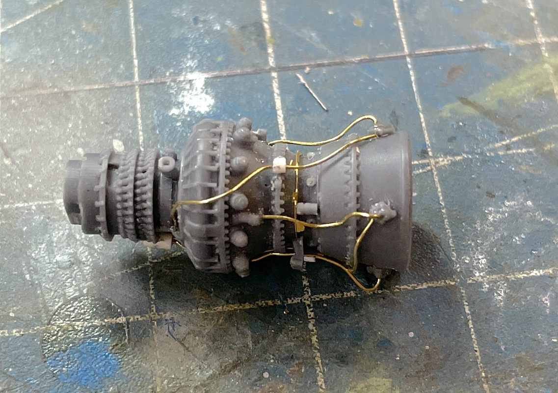
Today, albeit in a short session, I actually did complete the T700 build with the addition of engine mounts, the bleed air duct (I’m assuming that’s what it is), and some more resin piping. This piping was more robust so I was able to work with it. One I fastened with a piece of guitar string.
My new drills arrived. I ordered 0.012" instead of 0.010" and a slightly shorter length. This makes the drill just a little more robust and a slightly larger hole to make it easier to slip the skinny wire in. The 0.010" was just too tight a fit and the wire would often bend over when trying to insert.
I removed the flange around the exhaust duct with the Dremel.
I then tried it out and was rewarded with a nice tight fit.
I was only able to get one resin engine mount assembly to work and used one of the kit mounts to substitute. I put all the other remaining items on the engine and CA’d it to the bulkhead. I hope I won’t regret that step when I get to painting it. I like that it’s now captivated and is much more secure to hold onto it. Also, I’ll be able to paint over all the excess CA that seems to be floating around.
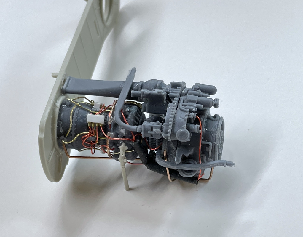
Tomorrow, I’ll build the kit left-hand engine and get ready to paint them. While I’m aware of all the not-so-hot things in this engine build, when you look at it from normal observing distance, it looks pretty cool.
Looks great.