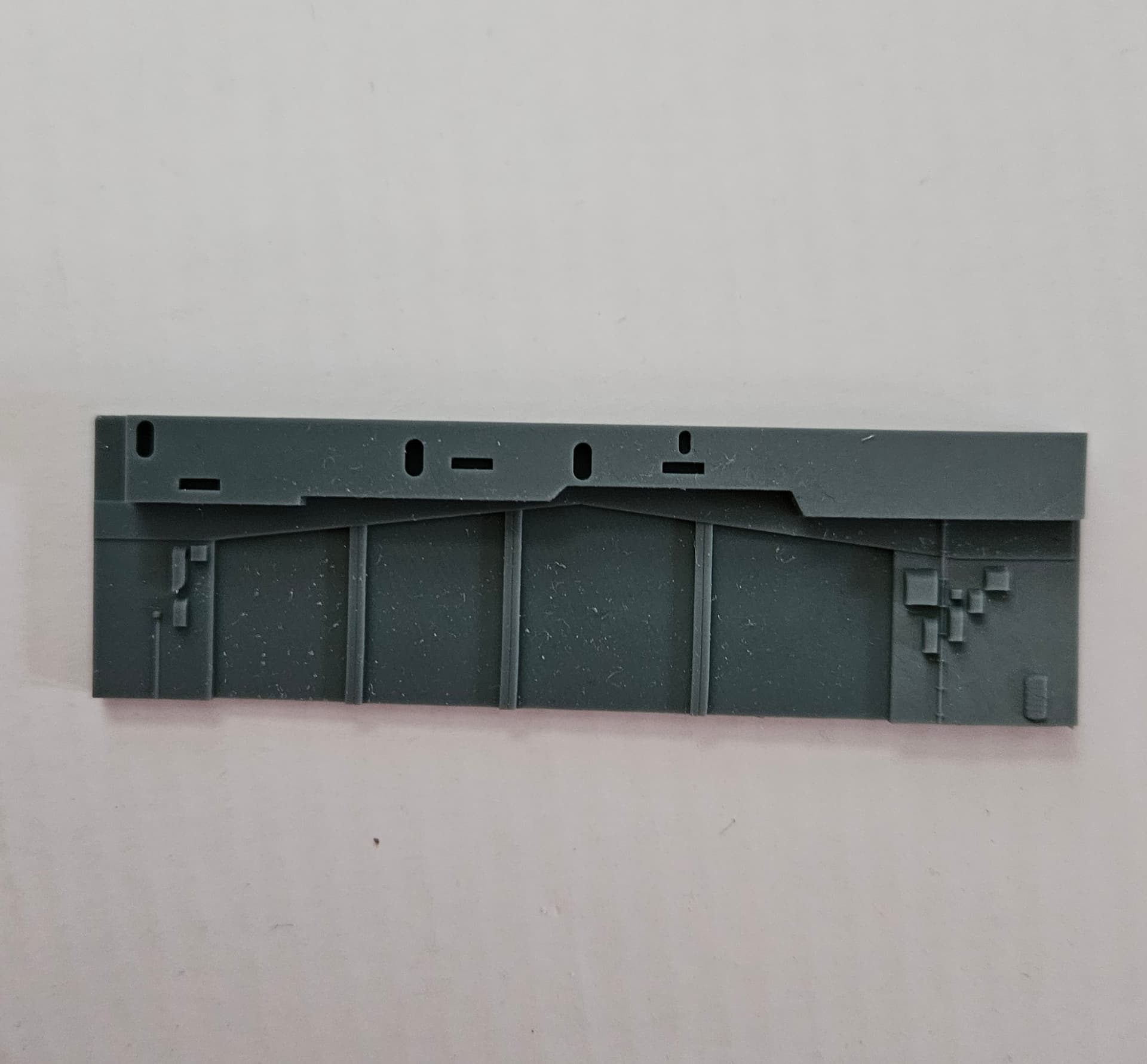
So, I found a Facebook group for modeling Essex class carriers and there was some good info out there about the Hornet, especially concerning the forward bulkheads on the hangar bay level that accommodated launching from the hangar deck catapult in WWII. Those doors were retained even after the catapults were removed (good for unreps and such). The Intrepid kit does not have those doors as they are on the Hornet, so more research (I thankfully have a great picture of the stbd doors) and more 3D printing. Here’s the photo and the printed part:

1 Like
Thanks for mentioning the facebook group. I had no idea it existed before your mention. You are continuing fantastic work on this…I’m loving it!
1 Like
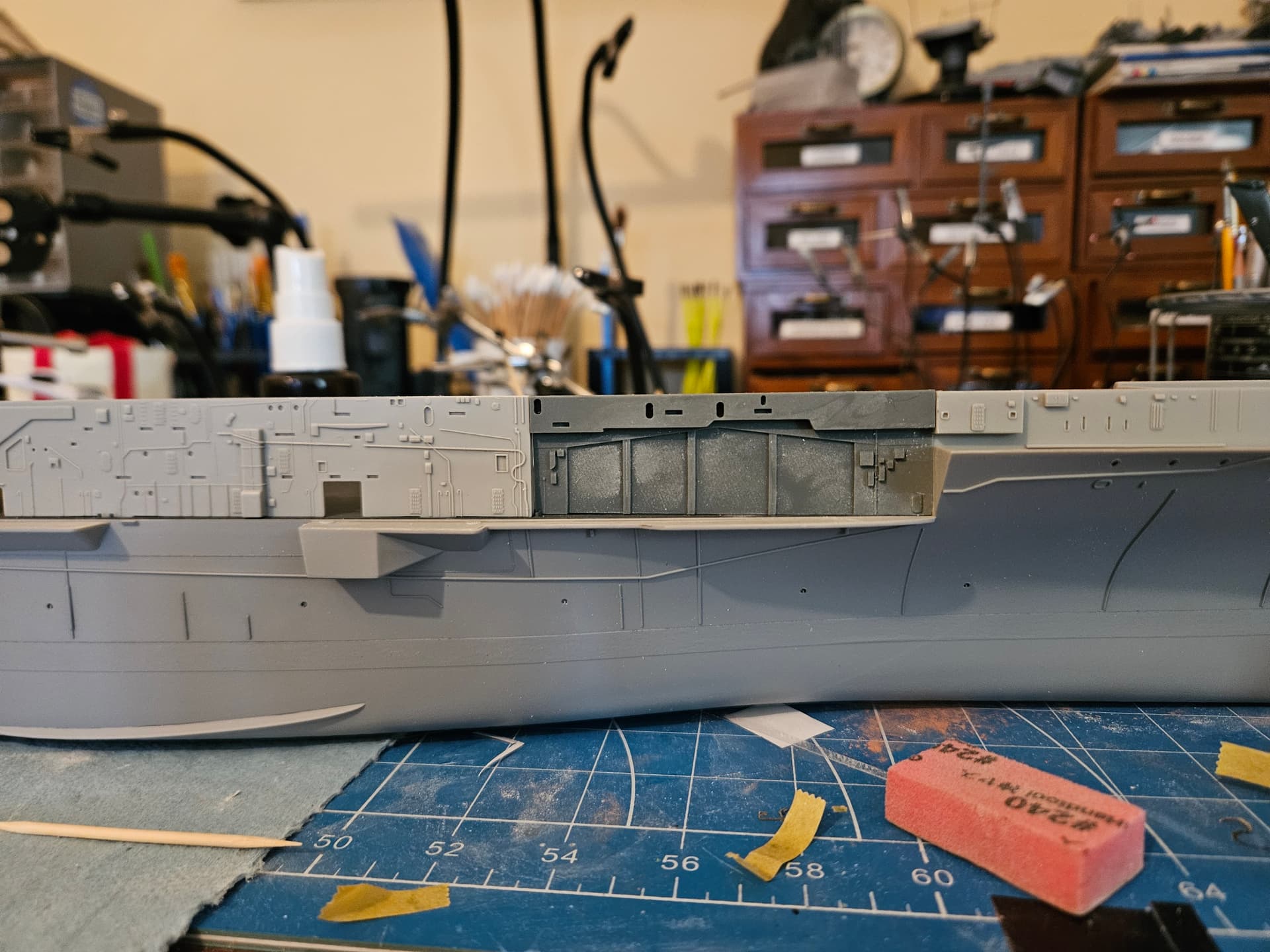
I cut the bulkhead from the kit and mated my printed bulkhead to the kit part. I did a test fit and it’s looking good.
1 Like
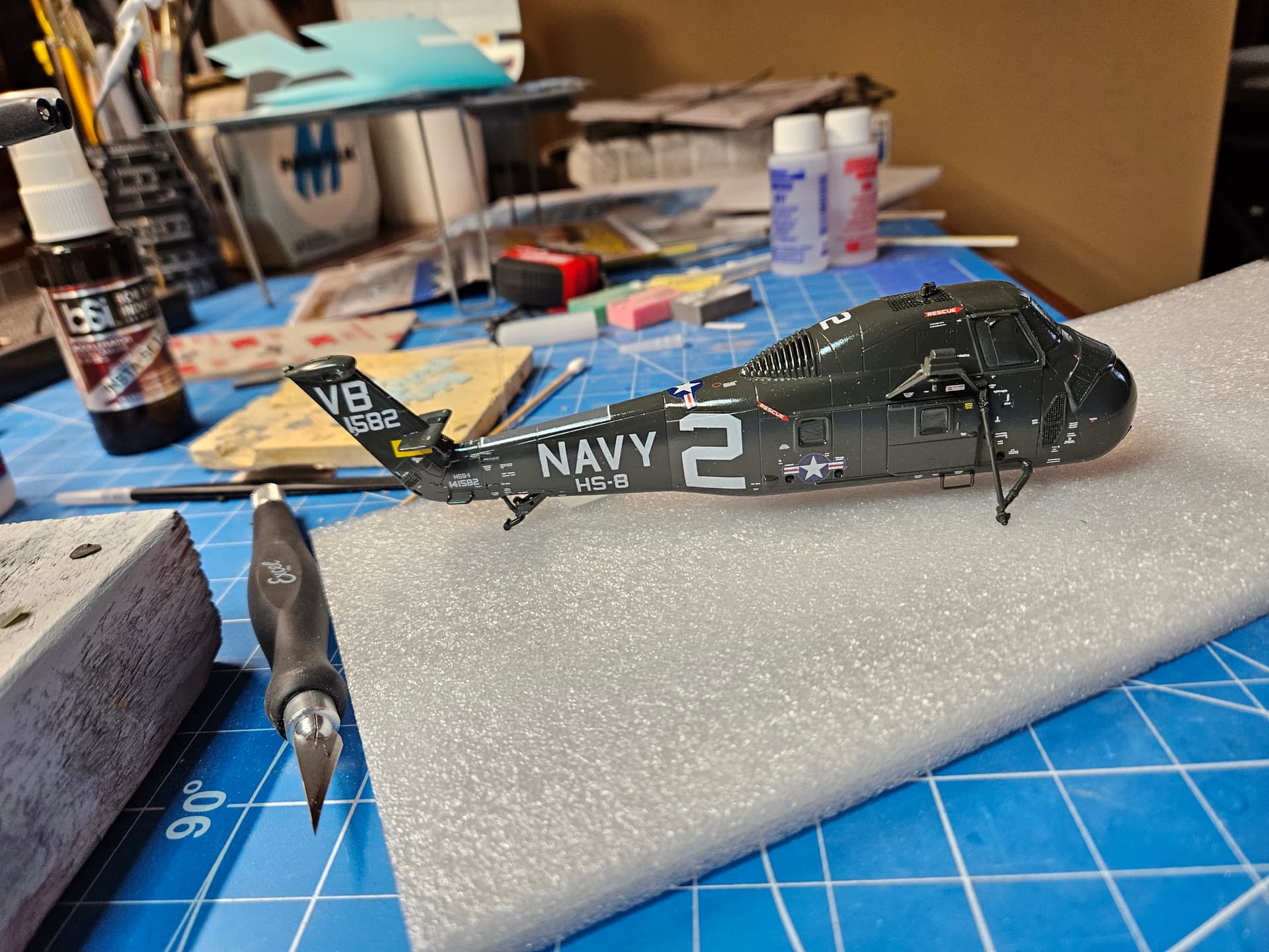
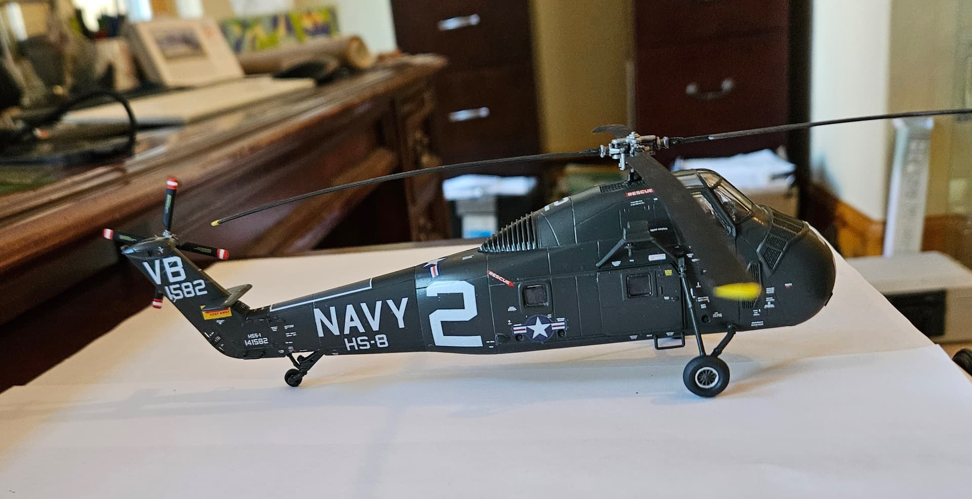
So, I took a brief interlude today to continue work on the HSS-1 Seabat from HS-8 that was on the Hornet during this cruise. I ordered some custom decals that I designed in Inkscape. The guy I use is based in Canada. I really like the quality of the decal paper he uses…it’s nice and thin, which can be an issue with some DIY decal papers. Anyway, with the new tariff challenges, the decals that he sent to me on December 24th only arrived earlier today…better late than never! I got the first side done today and will let it dry overnight and will tackle the other side tomorrow. Here’s the progress so far, along with a photo of the actual helo. Very happy with the decals!

1 Like
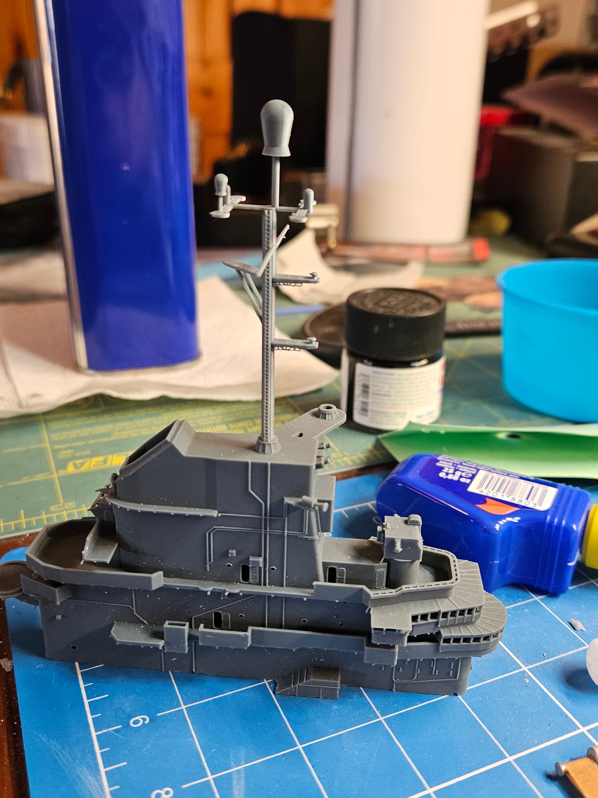
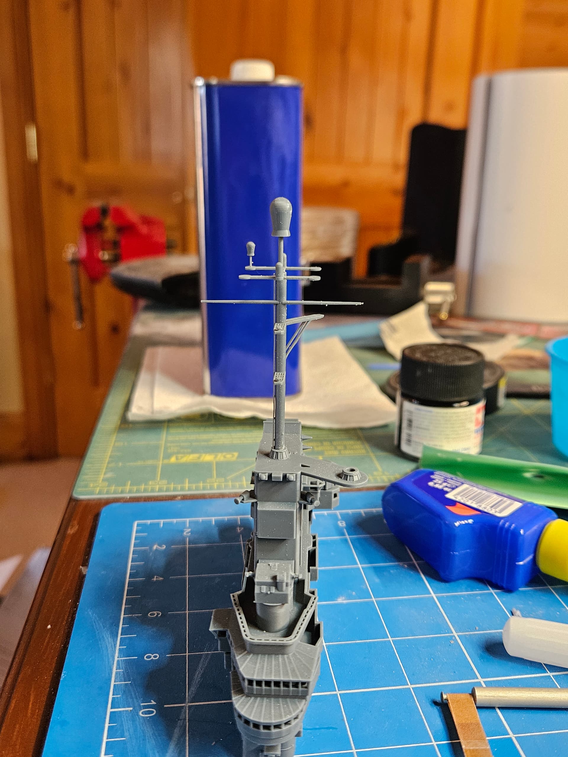
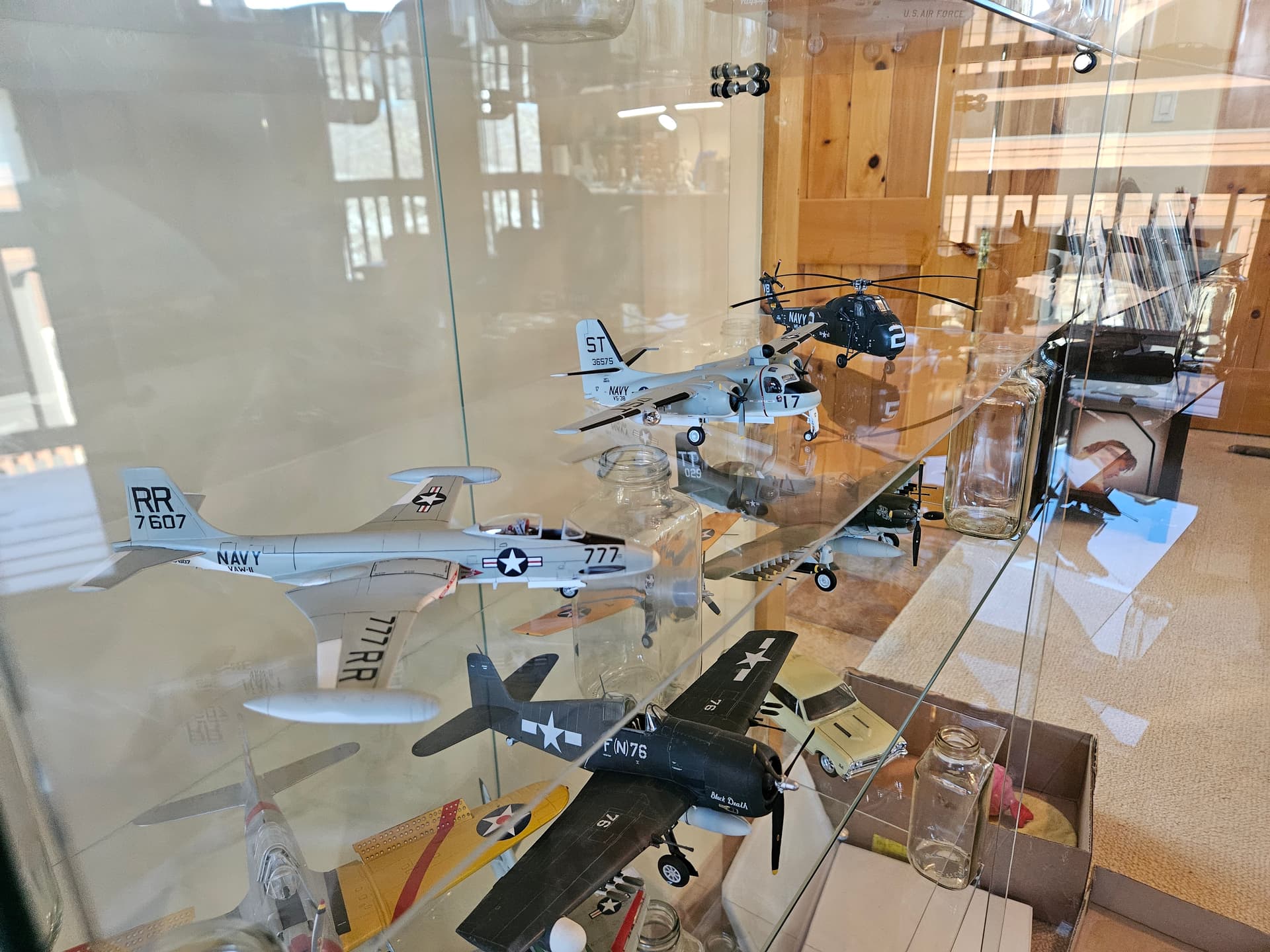
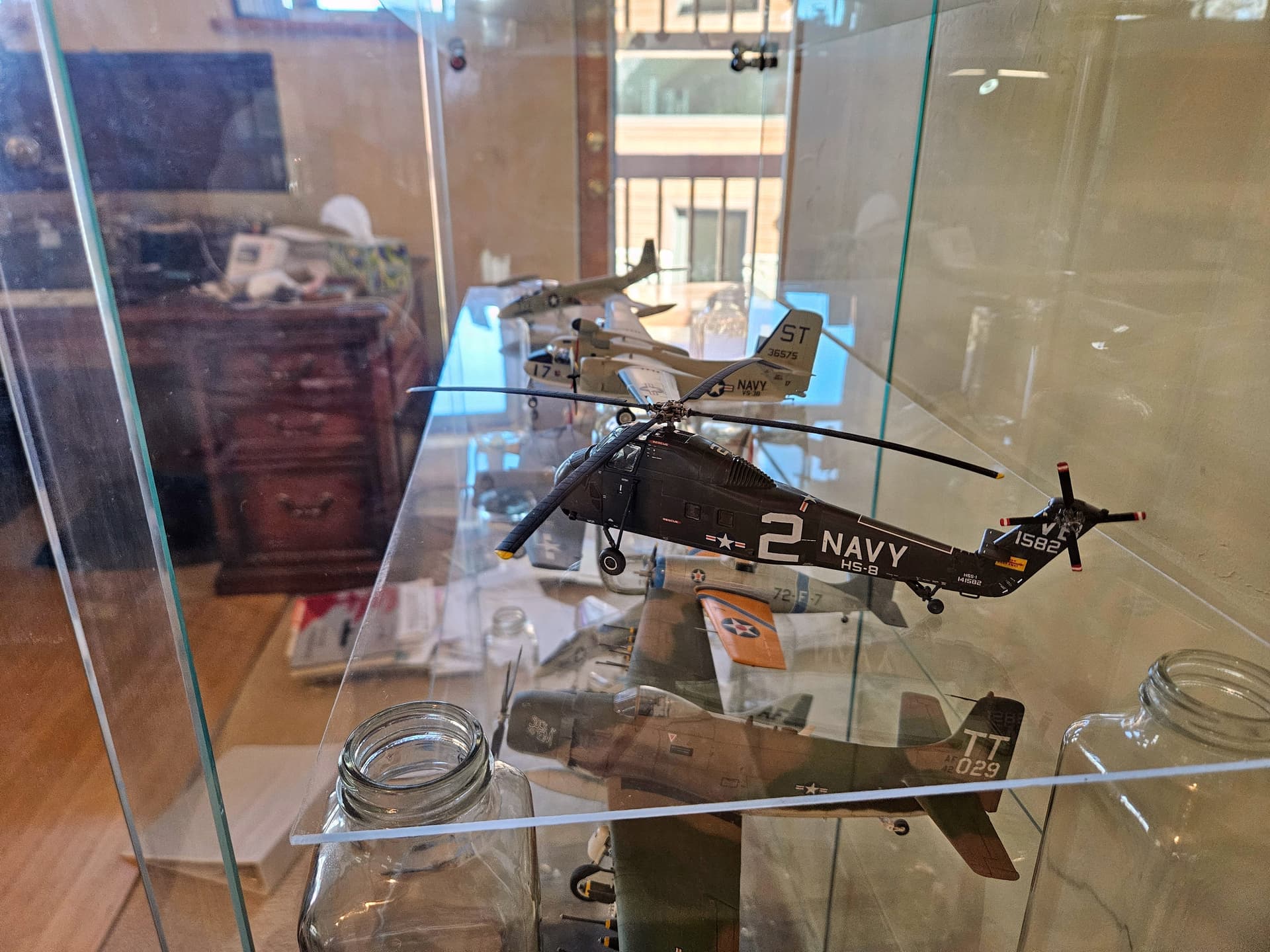
So, I have a couple of updates today…first, I finished my HSS-1 for HS-8. I now have a 1:72 scale representative for each aircraft type from the 1959 cruise, and they are all together in my display case. I really enjoyed building the HSS-1 and I really like the color scheme. I will do another one in 1:48 scale and already have the decals for the larger scale. I also decided the original mast I designed was too tall, and after checking against blueprints from Hornet’s sister ship, USS Yorktown, I re-designed the mast and included mounts for the SPS-6 and SPS-10 radars built into the platforms for each. They’re very small in the photo, but if you zoom in, you can see the detail. I also added the long ladder up the side of the main mast trunk. It was initially a thought experiment, as I was unsure how it would print, but as you can see, it turned out really well and leaves me with one less fiddly photoetch gluing and mounting challenge.
2 Likes
Quick update: I have not posted anything for a bit, but I will be going to visit the Hornet hopefully in about a month, and I plan to get some more detailed photos of the areas I cannot find good pictures for. After that, I expect things to ramp up again on the build. In the meantime, I’m working on another helo, this time an SH-2F Seasprite, Seasnake 17, which was on my first ship during our Desert Storm deployment. Work is underway and I have received the print of the custom decals I designed. The tactical paint schemes are not as good looking as the old engine gray helos, but it is what it is. I’ve designed and printed the ASW operator station, seat and other details along with the MidEast Force (MEF) IR Jammers and flare pods, as well as the FLIR pod.
1 Like
At last…some progress to report! We finally got some nice weather up here in the mountains, so I was able to spray the bottom of the hull. I used Tamiya Dull Red lacquer, mixed 50:50 with Mr. Leveling Thinner. I had some spatter initially because the needle was not fully seated, but I addressed that and re-sprayed. I’m very tempted to peel the tape and look at the boot topping, but I need to spray the upper hull first, then we’ll see how it turned out. I’m heading to visit the Hornet a week from Friday, so I will be able to finish my research and hopefully start accelerating the build again. In the meantime, I’ve been keeping myself busy with this side project
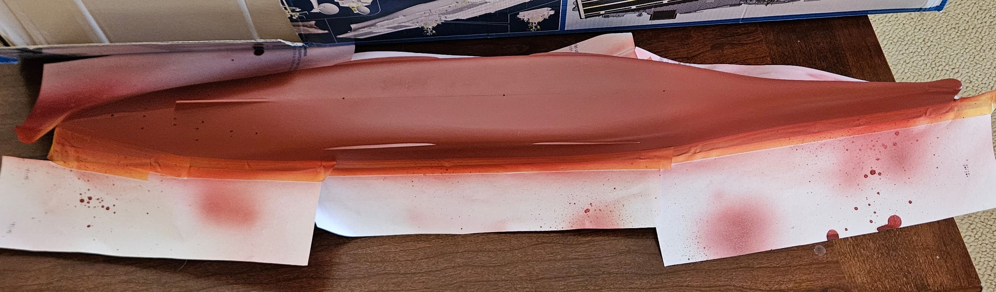
.
1 Like
In the spirit of paying it forward, I’m making available all of my original designs for converting the Intrepid into the Hornet. These are STL files for 3D printing and are available on Thingiverse. Check back over time, as I will continue to add/update as the build progresses and I refine various components. I am visiting the Hornet this Friday and should have plenty of material for updates after that. Here is the link to the the Thingiverse page.
1 Like
I visited the Hornet today and despite some heavy rain, it was a very successful visit. I first have to thank my good friend Ralph Johnson for making himself available today. After some coffee and catching up, we went around this great ship and I collected photos of the key areas to focus on. As I’ve decided to build out the hangar deck, I did much of my documenting down there. Here is a link to the photos if you’re interested. I have annotated the ones with measurements so you don’t have to decipher my chicken scratch. Next week, I’ll be getting back onto the Hornet build, equipped with this new info.
1 Like
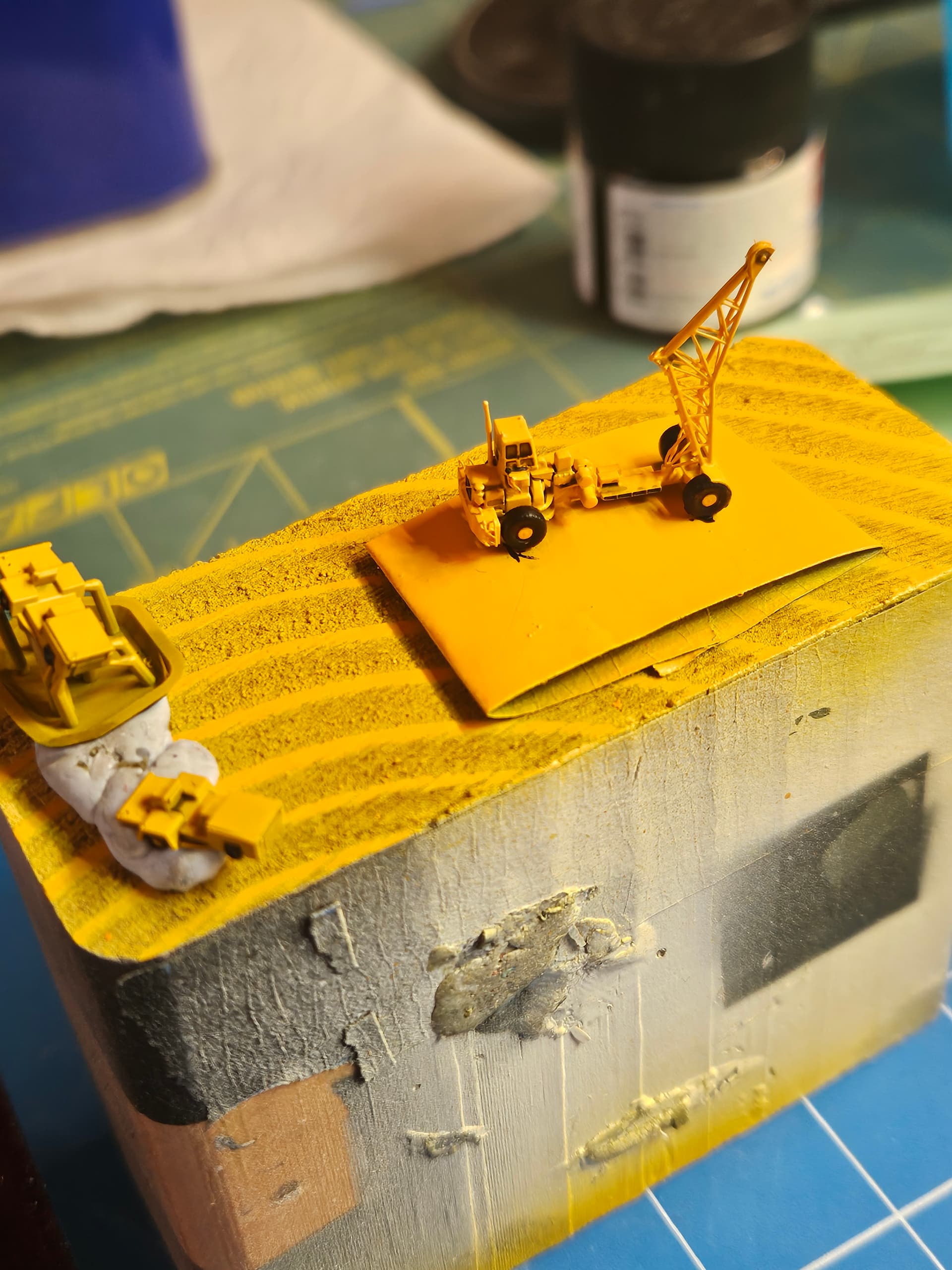
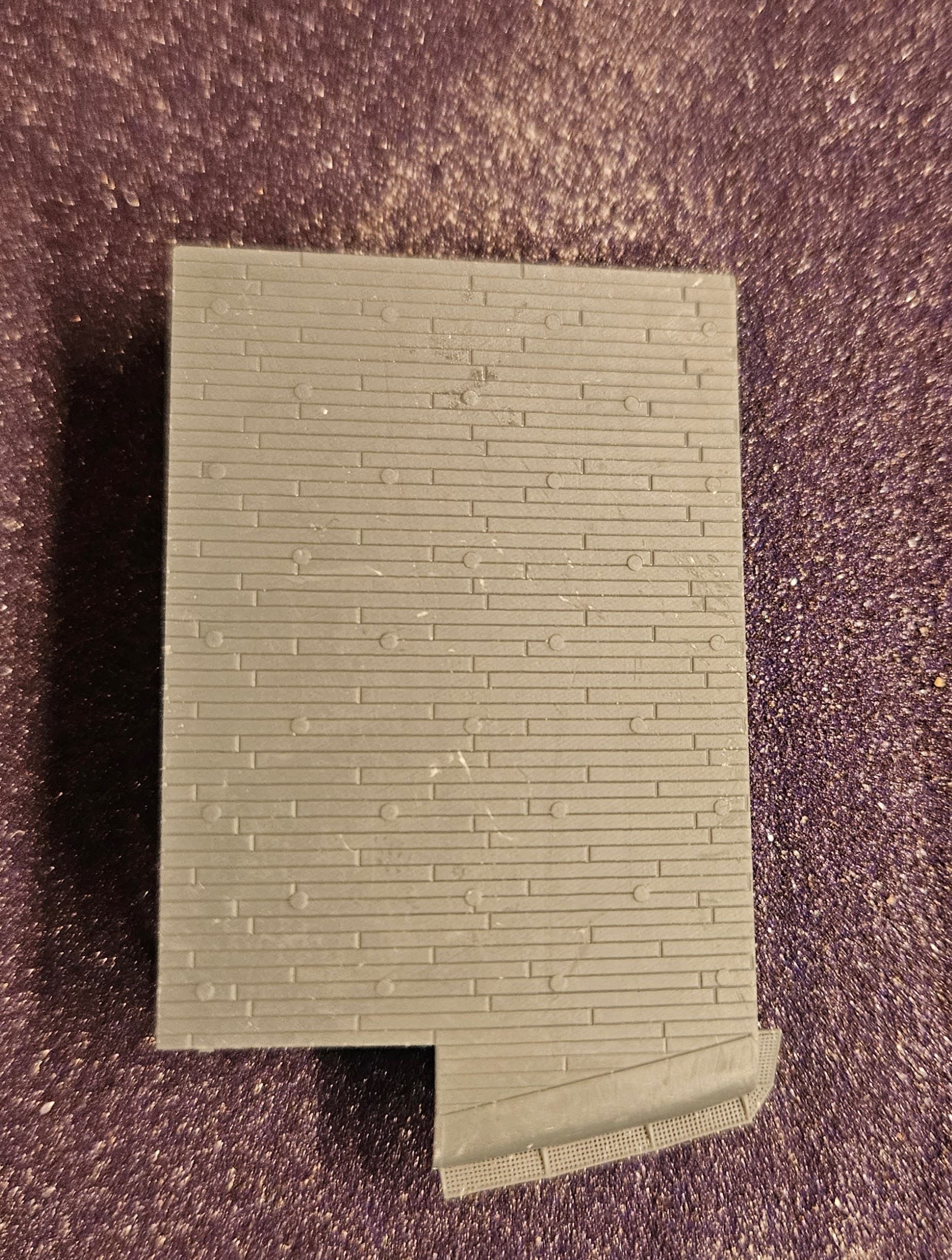
Well, I’m back from my Hornet visit and have already begun harvesting the dividends from my research. I was able to get really good looks at the #2 elevator and this is the result:
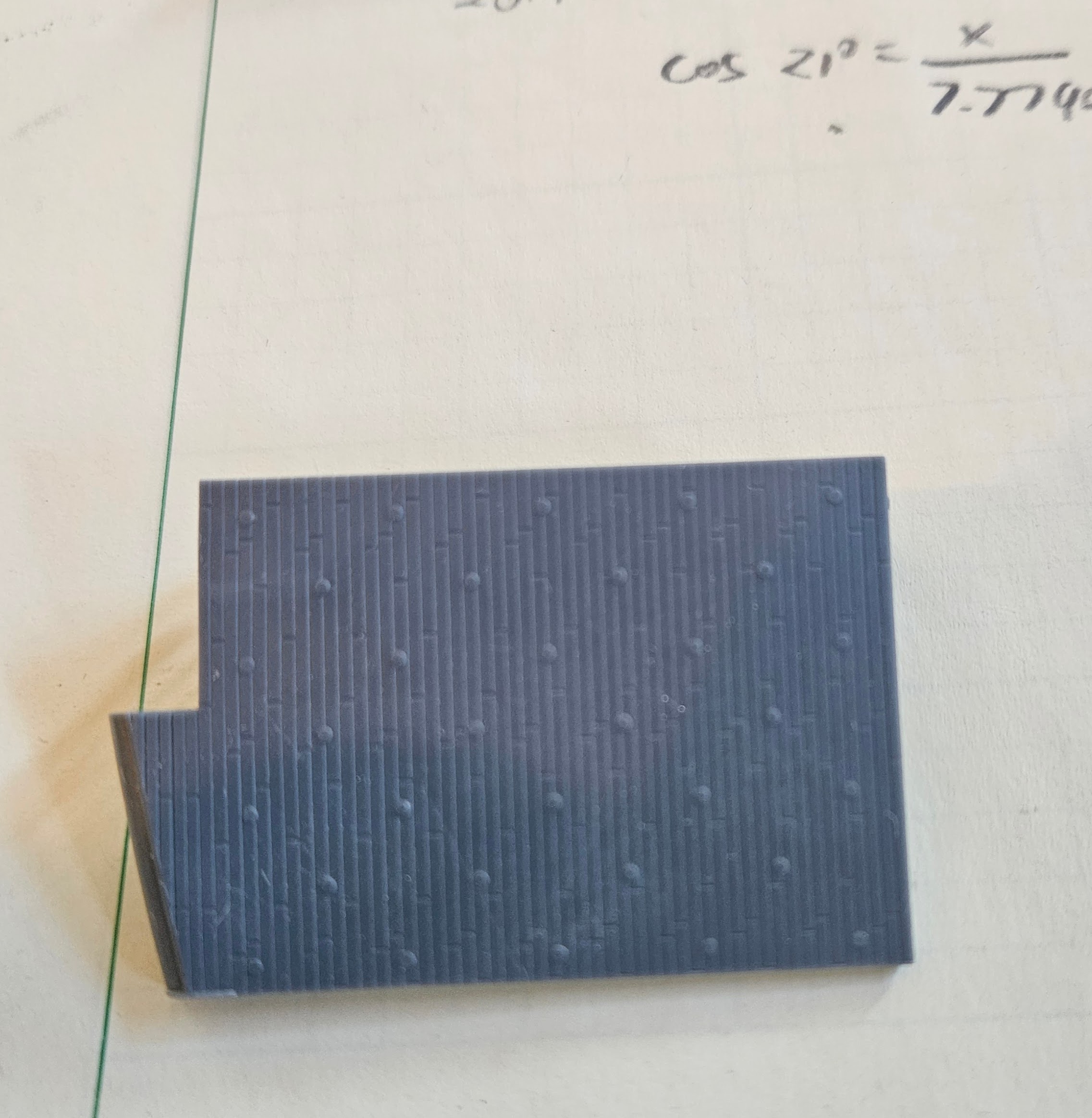
1 Like
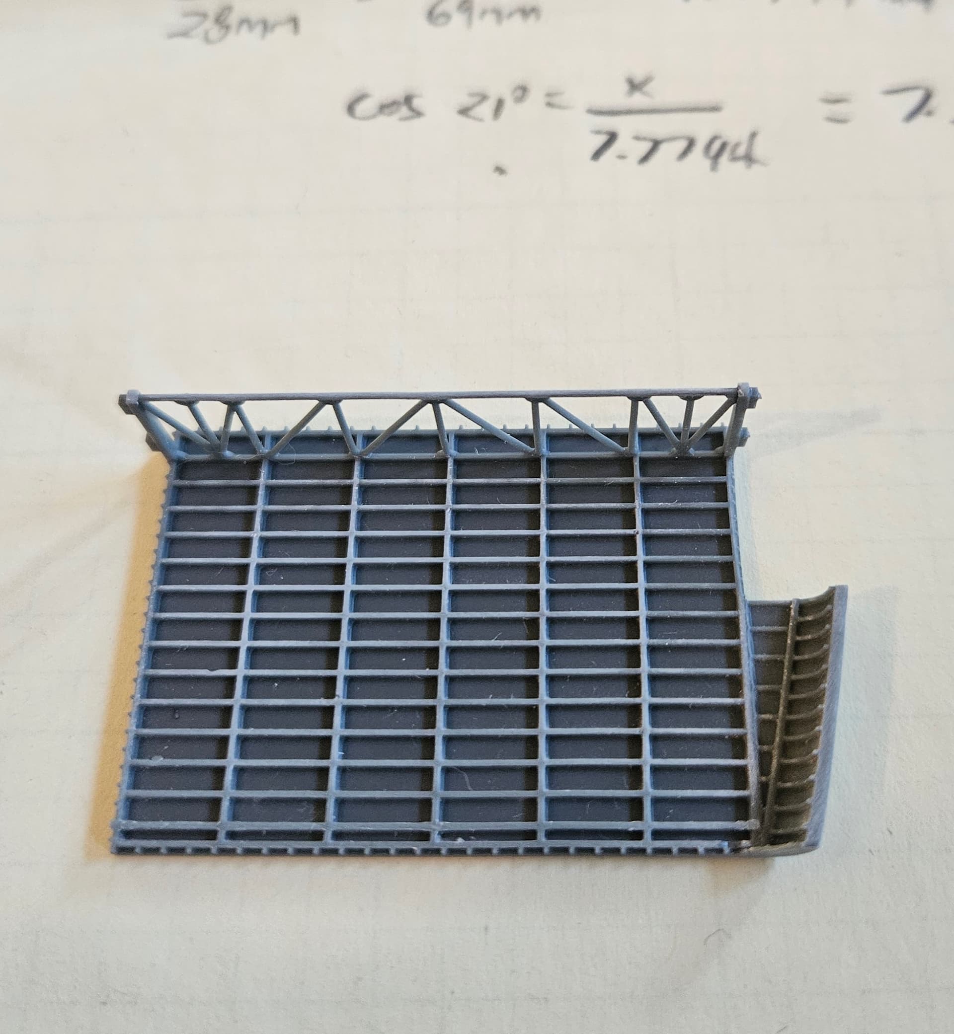
I made a few tweaks to the elevator today. I decided to see if my printer could do the safety netting around the ramp; I think it turned out really well. I also put a demarcation between the ramp and the deck planking. The truss on the underside is angled outward 3.5 degrees, as the rails that the elevator rides in are not straight up and down.
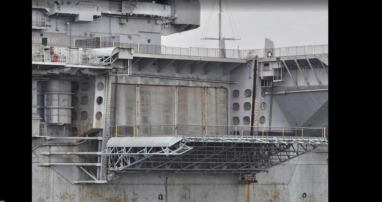
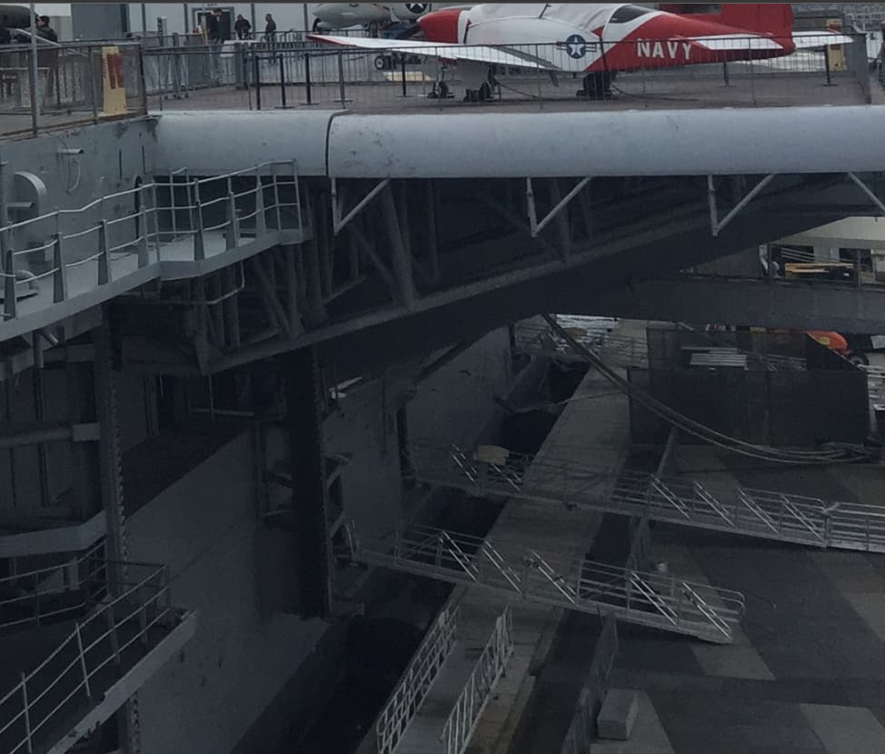
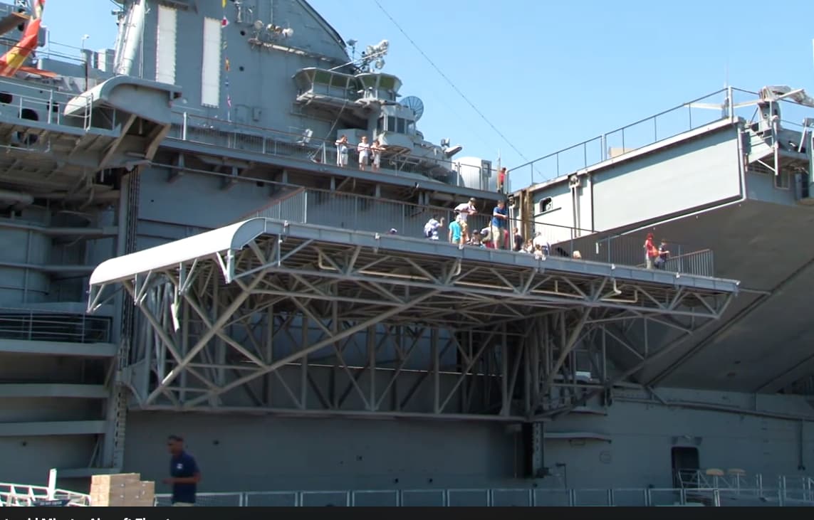
Well, I’ve hit another engineering challenge. The Intrepid has a somewhat different system for the #2 elevator tracks than does the Hornet. And since this is on the starboard side, and Hornet is moored port side to, it’s difficult to get good pictures and measurements of the elevator. Here’s a picture I took on my most recent visit, and knowing full well that I needed to make these modifications. I did not think it would be as challenging as it’s turning out to be. Note that the tracks for the elevator angle inward, approximately 5 degrees. This is meant to account for the fact that, at flight deck level, there’s a considerable amount of deck overhang to the superstructure, what I estimate to be around 5mm in 1:350. At the hangar deck level, this drops by about half, due to fact that the tracks angle inward as the elevator goes down. I did not account for this when I had the flight deck printed, so I am planning on printing a plug for the flight deck to close this gap. I will have to do the same at the hangar deck level. I am also considering moving the truss inward by a few mm to see what that does. It will probably look better if I don’t have to graft onto the flight deck. Since I plan on posing the elevator at the hangar deck, I could also just ignore the gap at the top, since a casual observer won’t be able to tell anything is wrong. The nuclear option would be to have the deck re-printed, but I am not seriously considering that…yet…
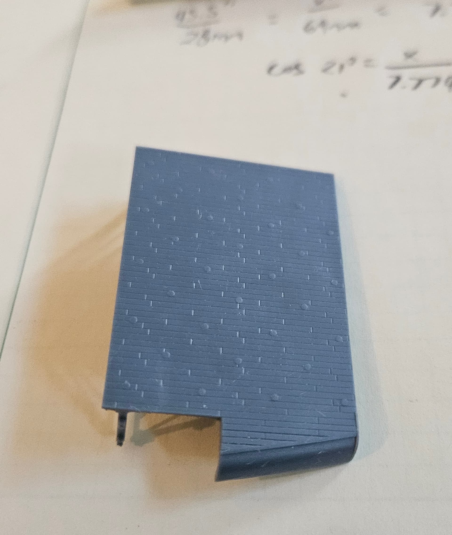
I had to design and print new superstructure aft of the elevator, since the kit piece is very different. That seemed to have worked ok, but I won’t know for sure until I do another test print and try to join it up to the rest of the superstructure. By the time I’m done, I will probably have replaced 75% of the superstructure on the port side, when originally, I thought I’d probably have nothing to replace there…
For comparison, I have included two screenshots of Intrepid’s elevator, and you can see that the track supports are totally different. They also appear to be almost straight up and down, moving without an angle on the tracks.
1 Like
After much deliberation, I’m going to re-print the flight deck, since the opening for #2 elevator was off by so much. Given the fineness of the planking detail, putting a plug in would be extremely difficult to achieve without obvious scarring; moreover, the outer edge of the flight deck behind elevator 2 needs to be extended by about 3mm to be accurate, and that has to angle into the flight deck as it goes backward. No easy way to make that fix. So, what I’m trying now is to print parts of the flight deck on my printer and see if I can join them up without obvious gaps. If that works, it’s only my time and some resin; if not, I have an order queued up to re-print the deck via the same vendor I used before. The good news is that I have test fitted everything and it should be fine with the new measurements.
1 Like