I cut the after bulkhead into 3 pieces to adjust for the new elevator location.
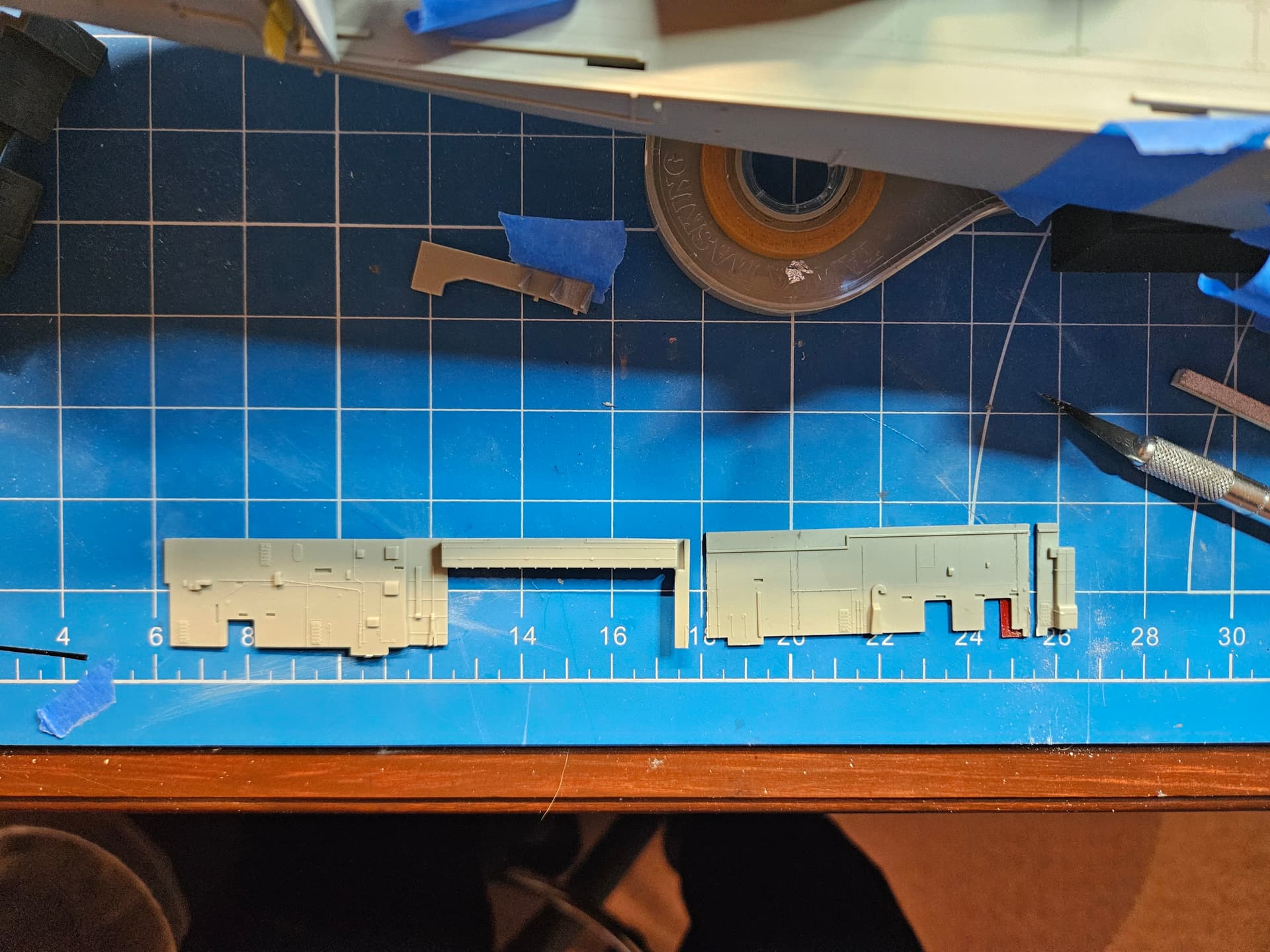
I glued the hangar deck opening section to the tiny piece on the far right in the picture above and dry fitted it along with the completely new after bulkhead that I designed in Blender and 3D printed. The Hornet had a substantial boat deck back here, with 3 roller curtains to enable movement of the ship’s boats from the hangar deck and back. I will probably make another print of this after bulkhead, as I’m not totally happy with the curing of the part. I will most likely also extend the forward part of the new bulkhead slightly for a cleaner join with the kit part.
1 Like
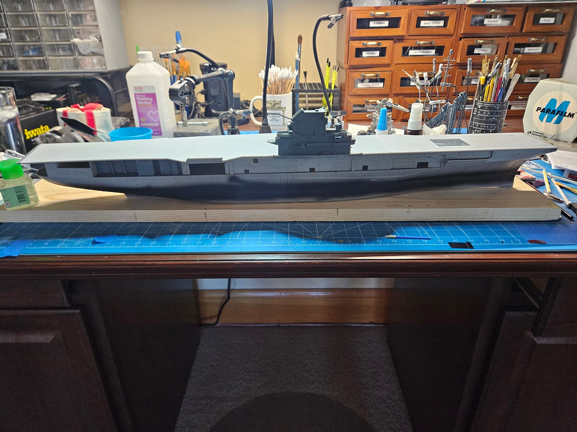
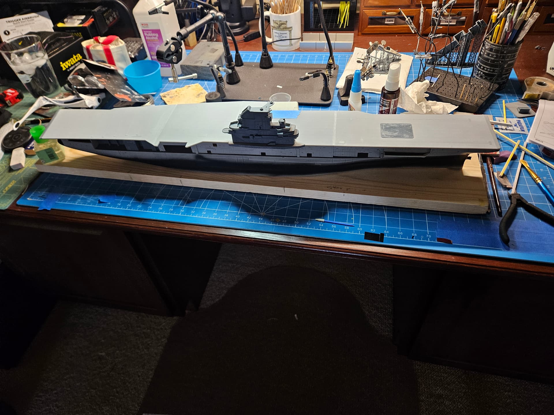
I have finally painted something and glued something on this project! I put the sonar dome on the hull, painted the hangar deck dark grey, and painted the boot topping line. I have masked over it and will remove some of the overspray before I hit the dome area with primer to check the seams. I should note that the Hornet of 1959 did not have the sonar dome yet, but the kit did not have the option for a dome-less build, and I did not think the juice was worth the squeeze trying to design it myself. Very few observers will catch this anyway. I did another round of dry fitting to make sure I’m happy with the alignment of everything. Oh, and I decided to light the hangar deck (at least Hangar Bay 3), so more to come on that part of the project.
1 Like
You’re doing great work here. Someday I’m going to build a Hornet as she is today, and your build log will be most helpful in the endeavor. Keep the updates coming!
1 Like
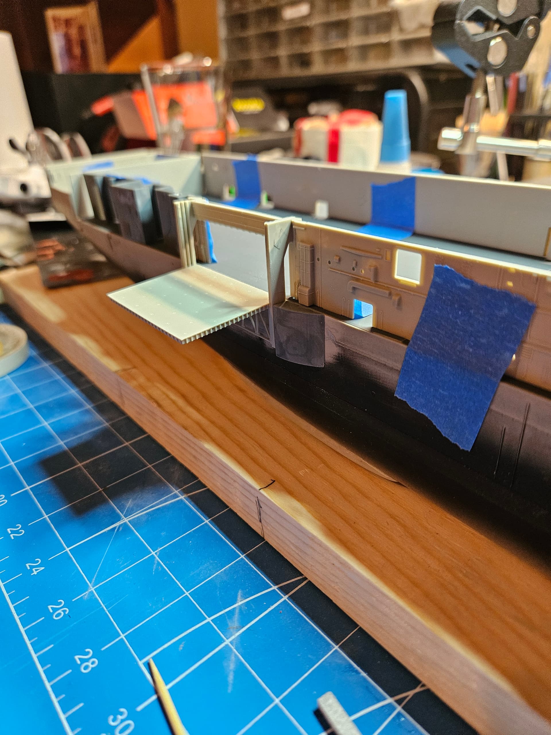
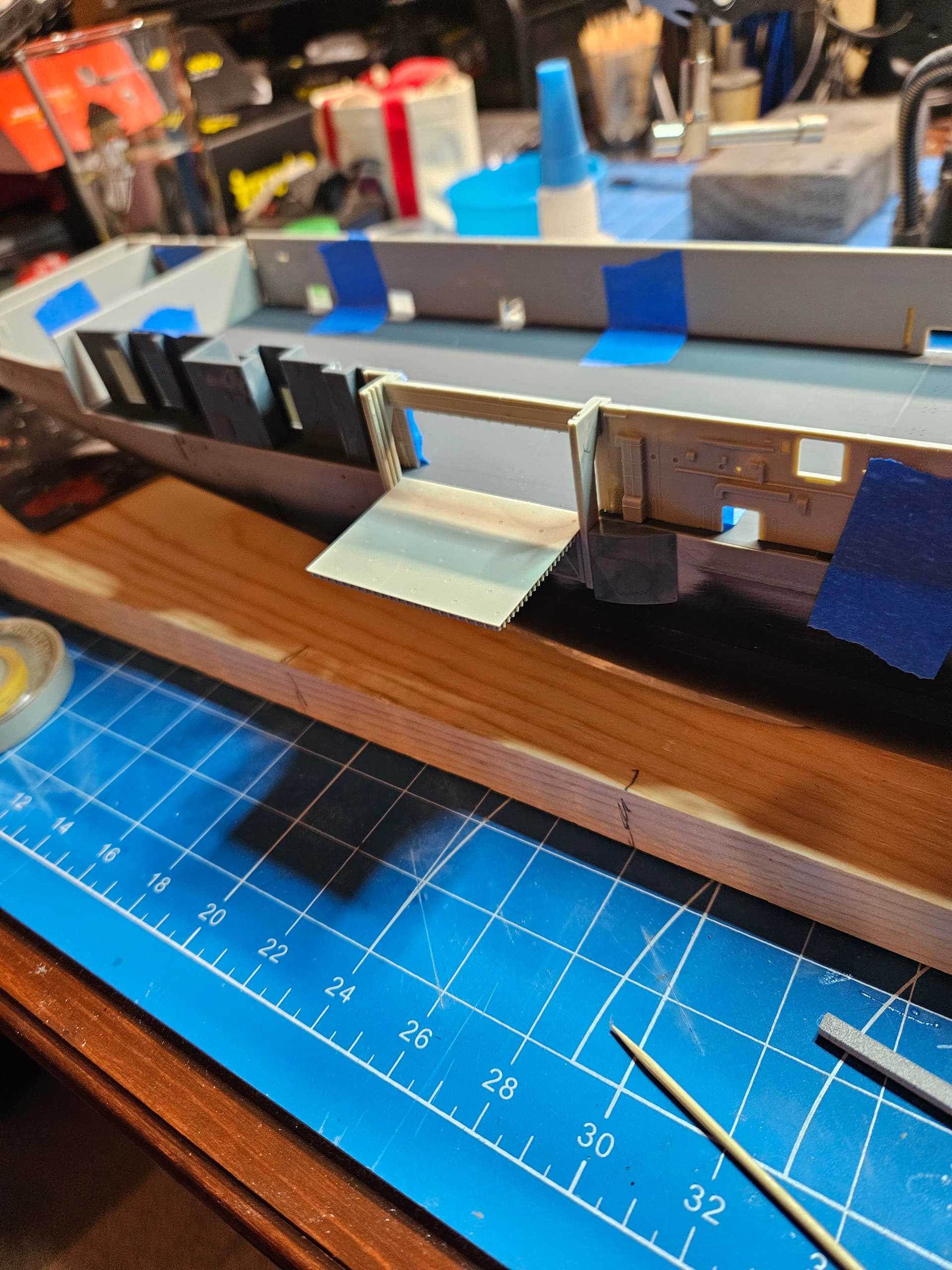
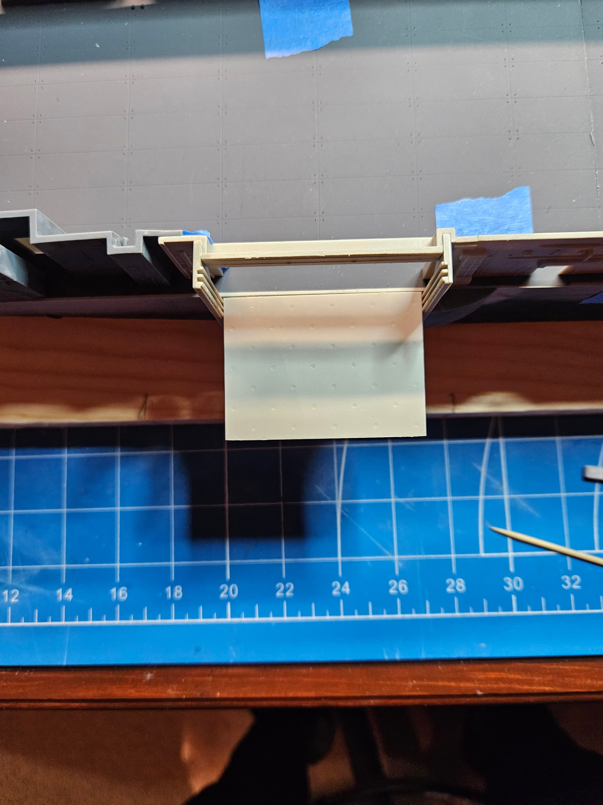
Thanks for the kind words, mrb865. I’ll definitely keep the updates coming! Today, I decided to make sure once and for all that I had #3 elevator aligned with the flight deck and the hangar deck bulkheads. Since I had to cut those parts and graft the hangar deck opening for the elevator further forward, I could not take advantage of the locating pins for the elevator guides (parts F6 and F7). I cut those pins off, along with the three triangular supports on each guide near the bottom. On Hornet, these guides attach directly to the sponsons, the forward one I 3D printed and the after sponson is the crane sponson, so it’s mainly a matter of moving that sponson to be flush with the guide, but getting those parts flush is not that easy. What I decided to do was to mount the elevator guide structure (part F5) to the elevator, so that I could insert it into the guides, which would guarantee they are correctly spaced. Once I had the elevator in the guides, I attached them to the the bulkhead structure, leaving the elevator in place as the glue set. Now, I can install the sponsons and when the time comes to mate the bulkhead and the guides together with the sponsons, everything should be perfectly spaced.
1 Like
I should also note that I’m posing the elevator in the lowered position, so making sure everything was flush with the hangar deck was very important.
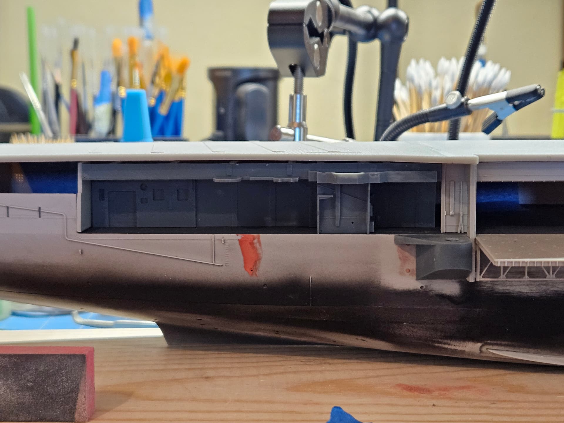
I have been fretting with the structure aft of #3 elevator. It has been very hard to find photos from the 1959 era that clearly show this space. I finally found a couple by looking at the Apollo 11 recovery and finding, of all things, a photo of sailors going ashore on liberty via the accommodation ladder, which happens to capture a couple of key features of this section. These were in the 1958 cruise book, which I found on line at navsite.de. I was happy with how my (4th) 3D print turned out, and it includes the 5" gun sponson, two antenna sponsons and the fire control director sponson. What I could not discern from the photos, I turned to the blueprints for the CVS configuration of USS Yorktown, which should be close enough. I also fitted the crane sponson (from Model Monkey) and am in the process of filling the holes from where the elevator guide rails were located on Intrepid. You can see clearly how much further forward the elevator is on the Hornet.
1 Like
This picture from navsite.de has been invaluable to me in modeling the after bulkhead structure. Thankfully, this is the starting point for sailors’ liberty, so I’m glad at least one cruise book captured that moment!
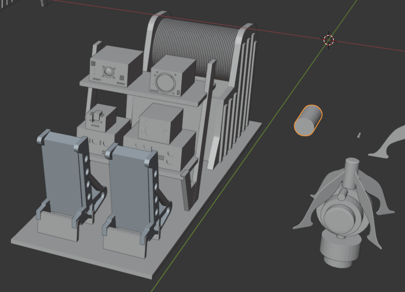
I am waiting for a router to arrive so that I can work on the base for the Hornet. I have a solid oak plank that I need to put a round over on, and then I will lay keel blocks. I will drill through two of those to mount the hull securely to the blocks. In the meantime, I have been building representative aircraft from the Hornet’s airwing. I have already built the S2F (what my Dad flew in) and the F2H-4 Banshee, both in 1/72 scale. I’m now working on the HSS-1 Seabat, but it needed an interior for the ASW operators, so I put one together in Blender:
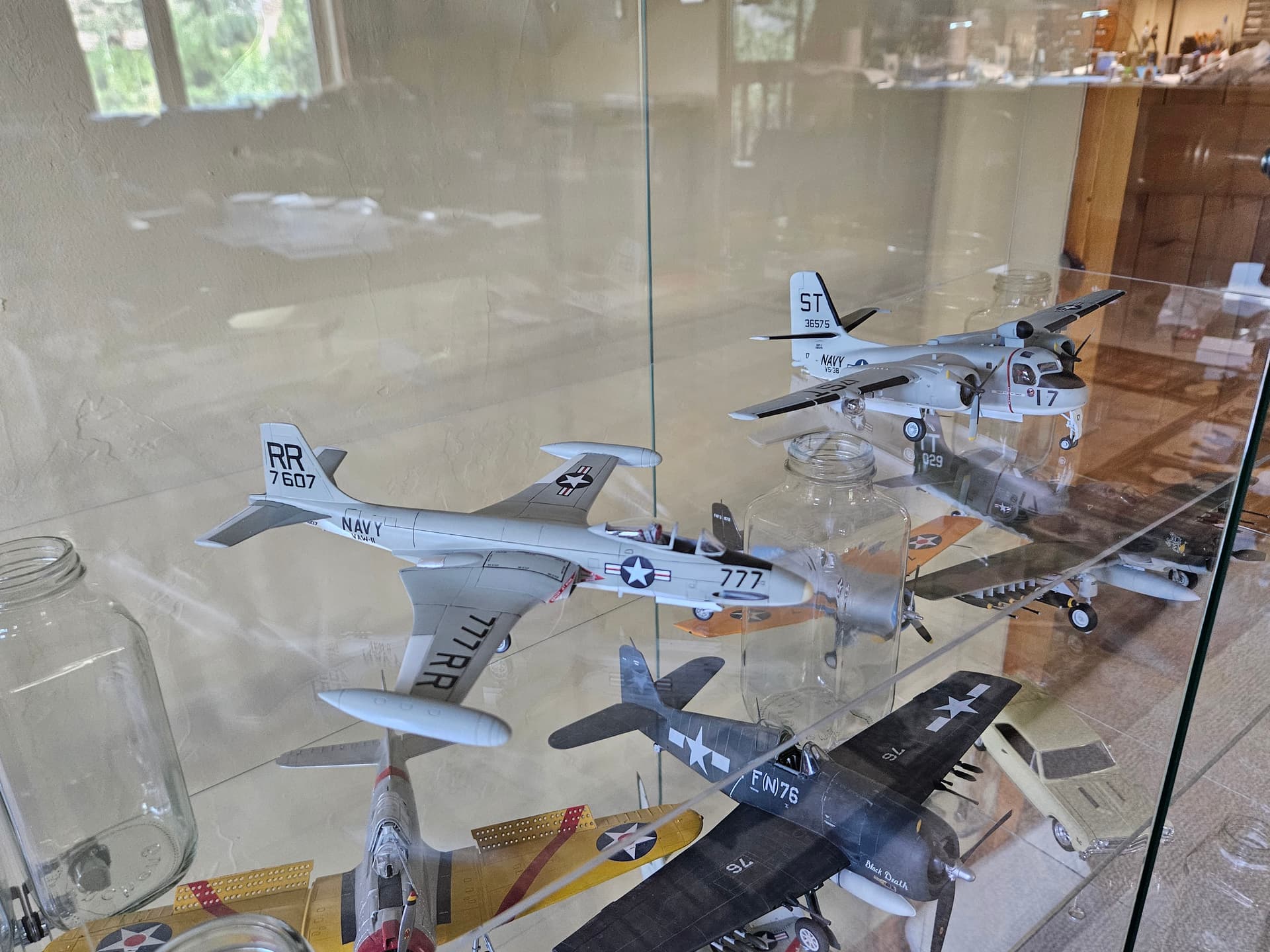
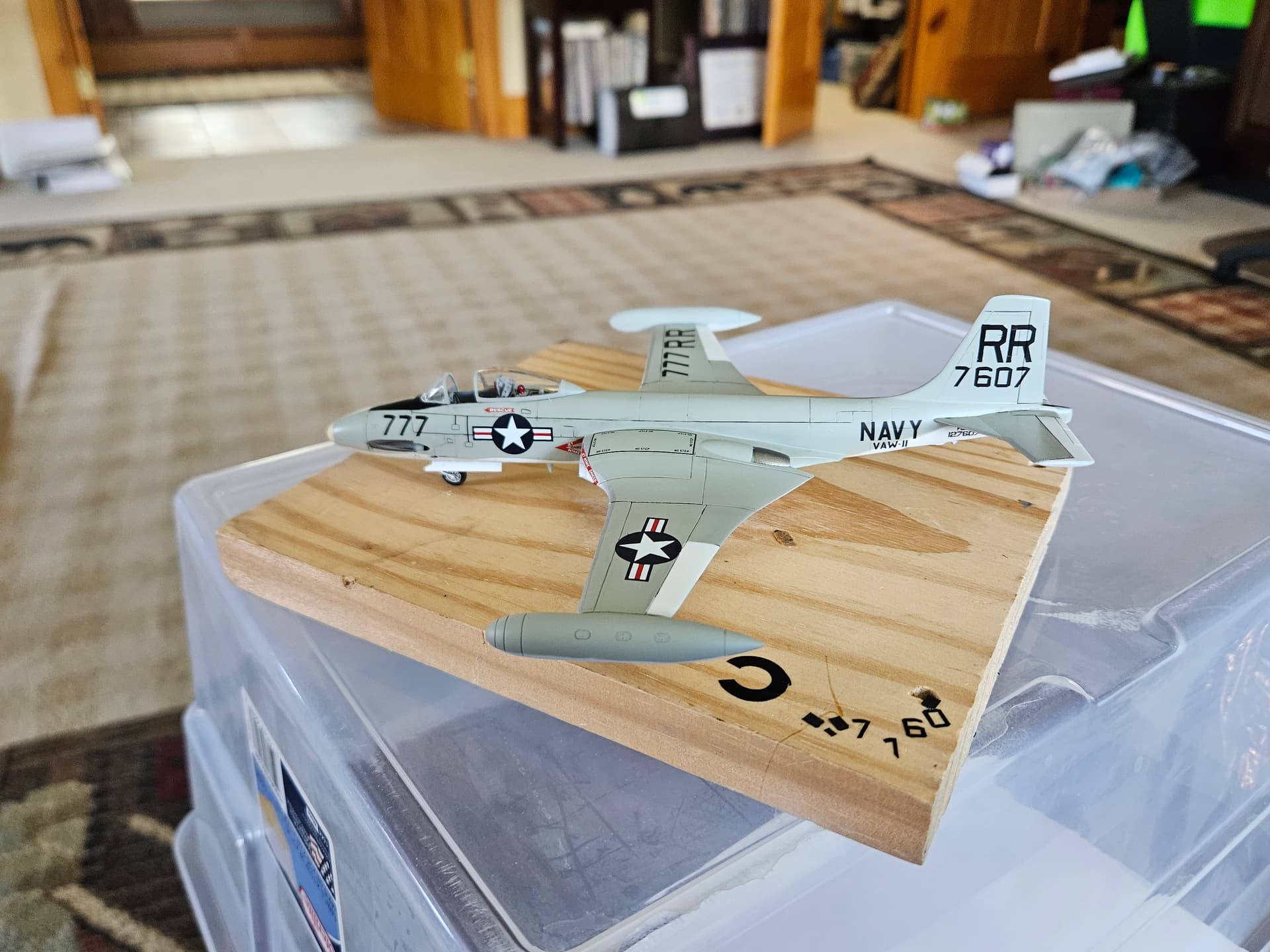
Here’s a picture of the finished Banshee, and another where it accompanies the finished Stoof. I made all the markings custom. On the Banshee, I used Cricut masks to spray the RR and the BuNumber and Buzz Numbers. On the Stoof, I printed custom decals (I did not have the Cricut yet). I will be doing these again, albeit at 1/5th the size of these models once I start work on the airwing. I will need a stronger set of lenses for my magnifier!
2 Likes
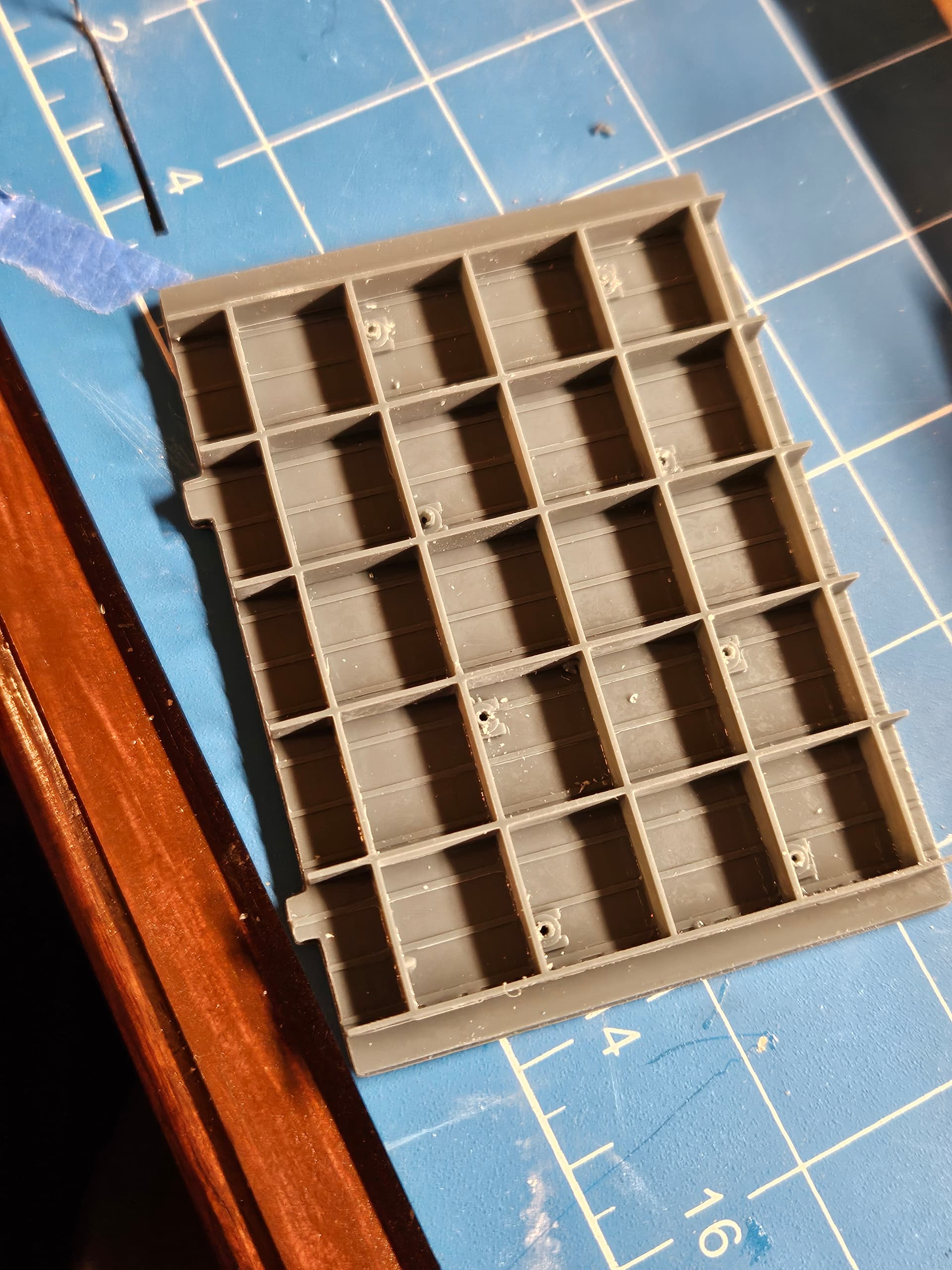
I’m now working on designing the overhead for the hangar bay. I was able to use my contacts at the Hornet Museum to get some good photos of the overhead, and the light locations. I am modeling this design in Blender, and I will drill out the lighting holes to run Z LEDs from Evan Designs into each fixture (at least that’s the current plan). I’m printing this Blender design now and will use this sample to check fit in the hangar and with the flight deck overhead.
Here’s the printed test piece. I learned 2 things from this:
- The piece was a bit wide, so I’ll be trimming a couple of mm off the width;
- Drilling through the light fixtures on cured resin with a pin vise is problematic. I will either need to use the Dremel, which will be harder to control, or I might just try drilling before I cure the resin.
More experiments to follow, but I’m pleased with how it turned out in general. If the LEDs fit in these holes, this could look really good.
More experiments to come…
I also decided to use locator tabs to keep all the overhead parts aligned. I can only print about 60x80mm in my printer, so I will have to do a number of increments. I’m thinking that, to keep the project manageable, I’ll just do Hangar Bay 3 and will close the fire doors between Bays 2 and 3 so that I don’t have to do the rest of the hangar bay, which will not really be otherwise visible, since the #1 and #2 elevators will be in the up position.
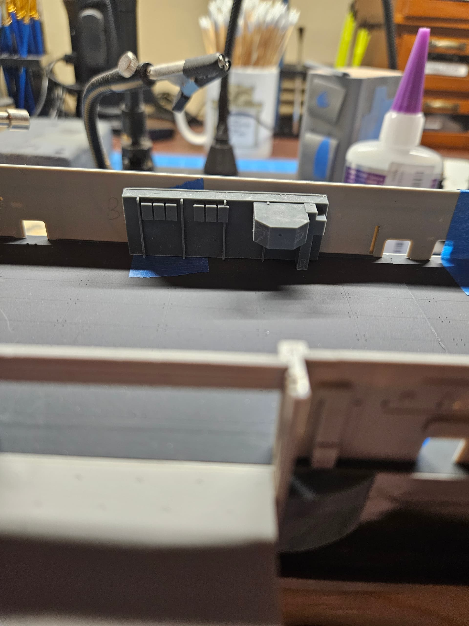
Now, I’m waiting on the LEDs to arrive for test fitting in my hangar deck overhead. Today, I modeled the #3 Conflag station, which is in the aft port corner of Hangar Bay 3. Proportions look good, but I will have to do some work to get the overhead and #3 Conflag to fit together properly. Fortunately, 3D printing only requires time, as the prints themselves are pretty inexpensive. Scratchbuilding the Conflag station the old way would take hours and the payoff in that case would be low, but with 3D printing, I can get a design to the printer in less than an hour and then print it in about an hour. I also enjoy designing the various components in Blender. The learning curve is steep at the beginning, but once you get into it, you learn fast and I get lots of help when I need it from Chat GPT.
1 Like
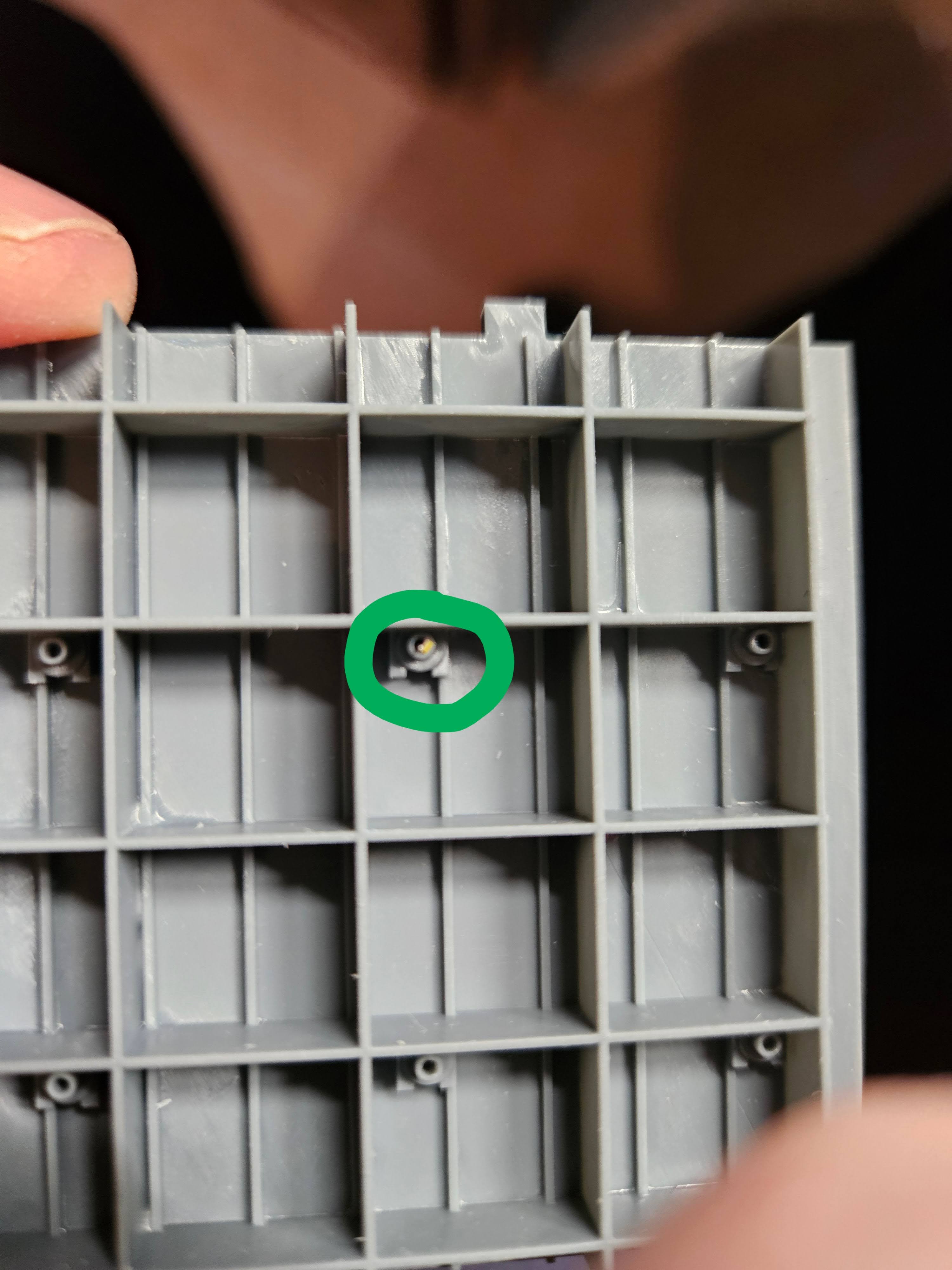
I just got my LEDs from Evan Designs today. They are chip LEDs, size Z, and they fit inside the lighting openings I made in the hangar bay overhead. These things are amazingly small (~.6mm wide) and they throw of ton of light…what an incredible product! Now, it’s time to start working on wiring all this up in preparation for installation. The little yellow rectangle you can barely see inside the circled light fixture is the actual LED…amazing!
1 Like
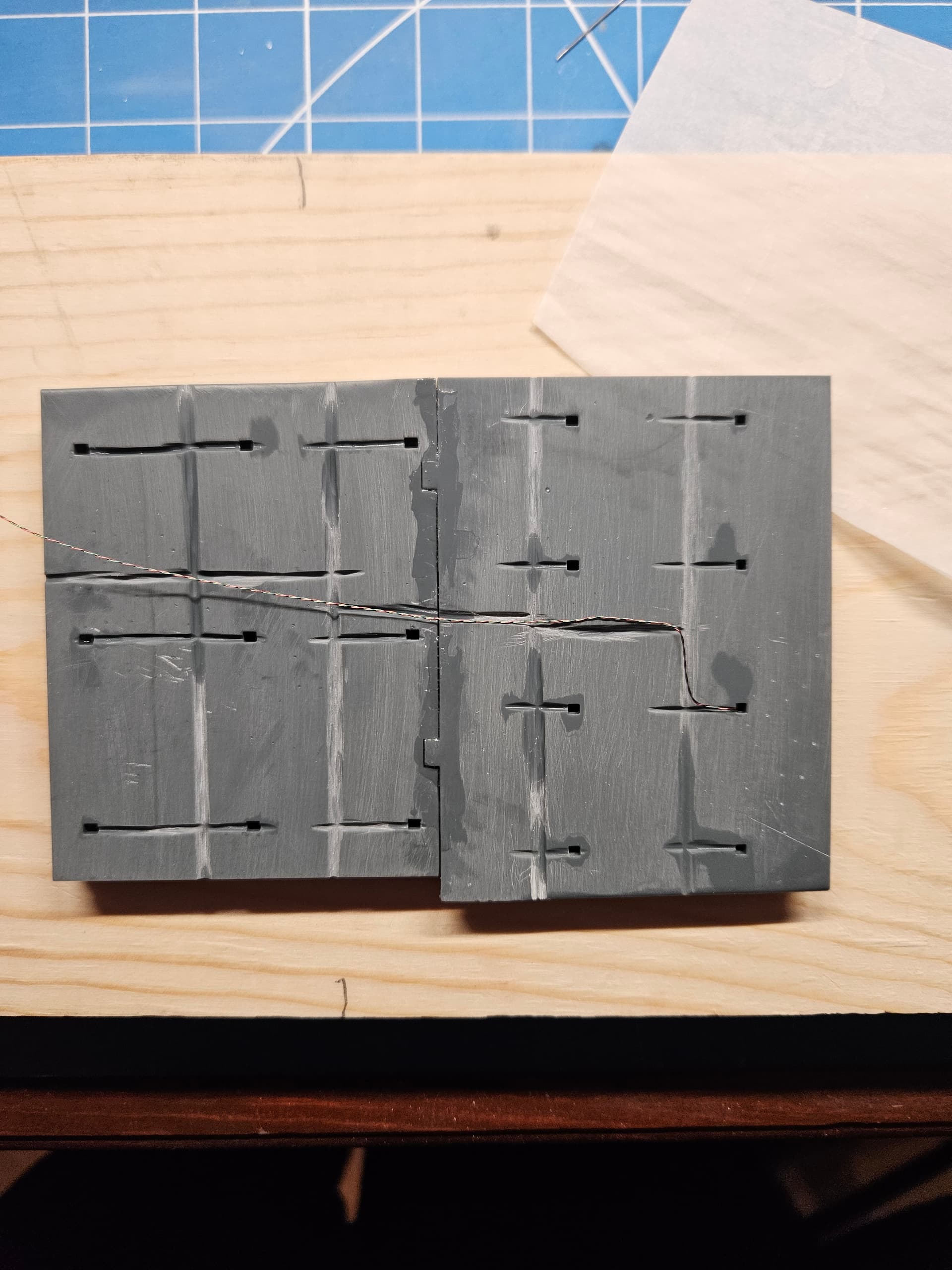
I joined the two sections of the overhead together today. I’m not going to worry too much about cleaning up the joint between them, as unless someone is poking a dentist’s mirror into the hangar bay, you’re not going to see the joint. My main focus today was cutting a channel on the backside of the overhead to accommodate the LED wires. They are super fine, but I did not want to leave anything to chance, and this gives me some guides for routing and securing the wires. I was not concerned about neatness of these channels, since they will never be seen again once the flight deck is installed.
I also changed my strategy on the interior hangar bay bulkheads. Originally, I was trying to make them thicker and stiffer, but that just seemed to exacerbate warping, despite many efforts on my part to straighten them. Therefore, I’m going to go with relatively thin (1.5mm) bulkheads that I can glue to the external bulkheads and just have them conform by force. These are a bit more fragile, so cutting them from their supports is a more delicate operation–I broke 1 bulkhead in half even before curing, and another chipped at a thin point. I may just re-print them with a few minor adjustments.
1 Like
Merry Christmas, everyone! I took some time off from working on the Hornet to work on the last remaining member of the airwing that I had not yet built in 1/72 scale–the HSS-1 Seabat, which flew on this deployment as part of HS-8. I am now decaling the model (there are many stencils and they are very small!), and after that, I will resume work on the Hornet. Next up for me is to get the display base put together. I’m using a piece of oak, and I need to work up the courage to use a router for the first time to put a roundover on the board. Once I have that done, I will put keel blocks on top and will drill holes for the mounting hardware and the LED wiring. Once that’s all done, I will get the hull ready for painting and will likely mount it to the base or to a temporary base while I continue working on it. Here’s a picture of the work in progress…if you squint, you can see the stencils near the nose!
2 Likes
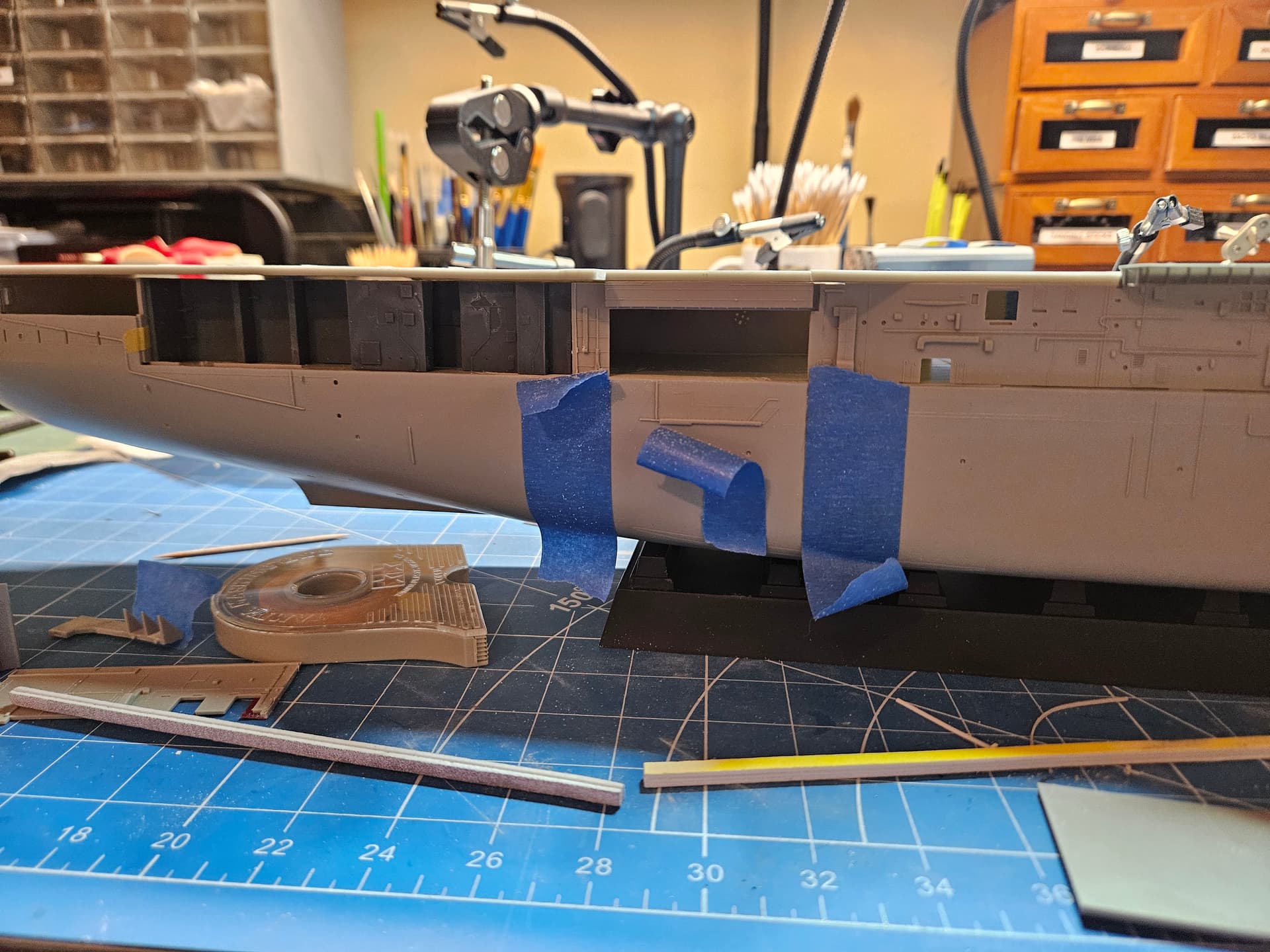
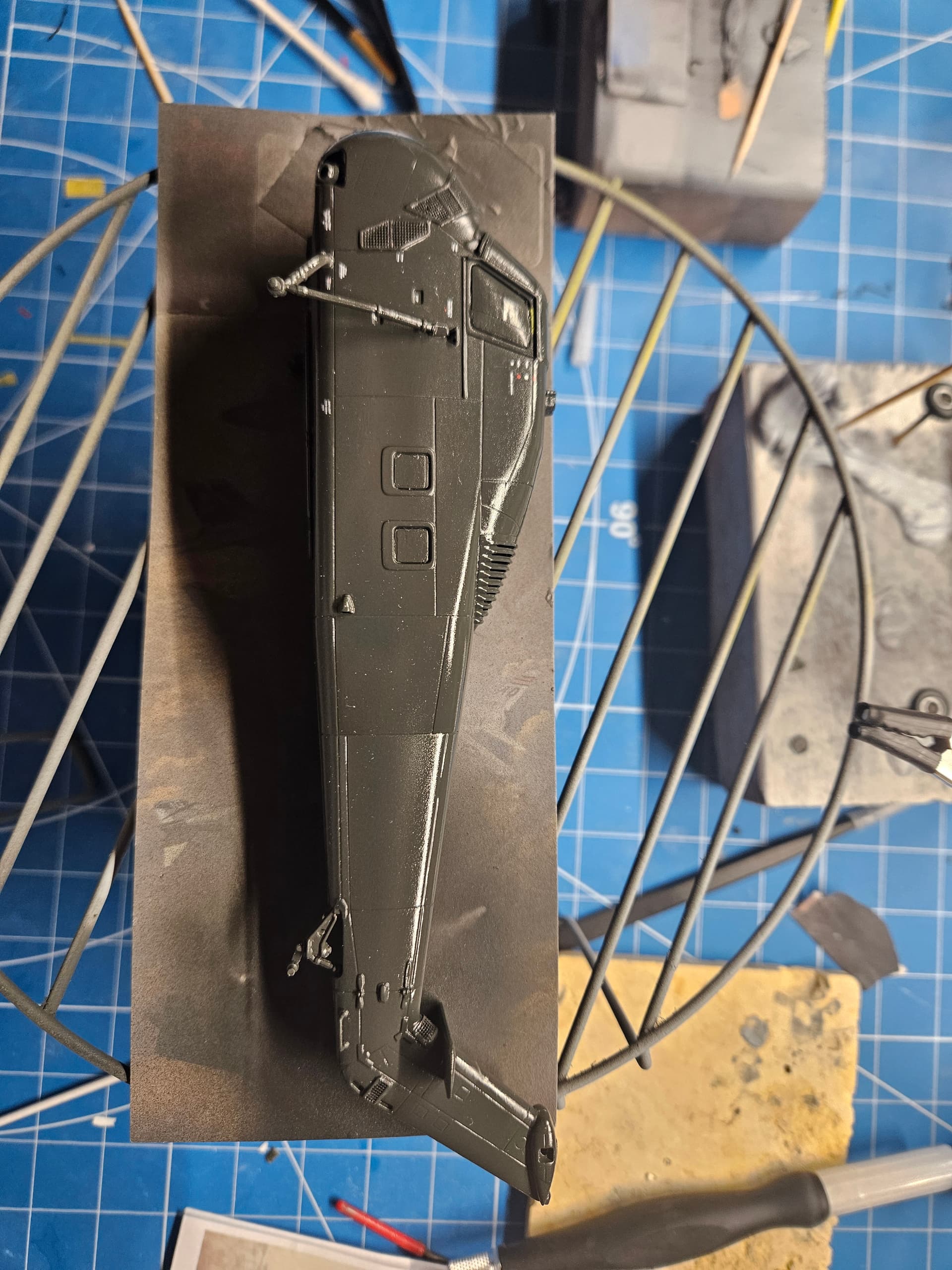
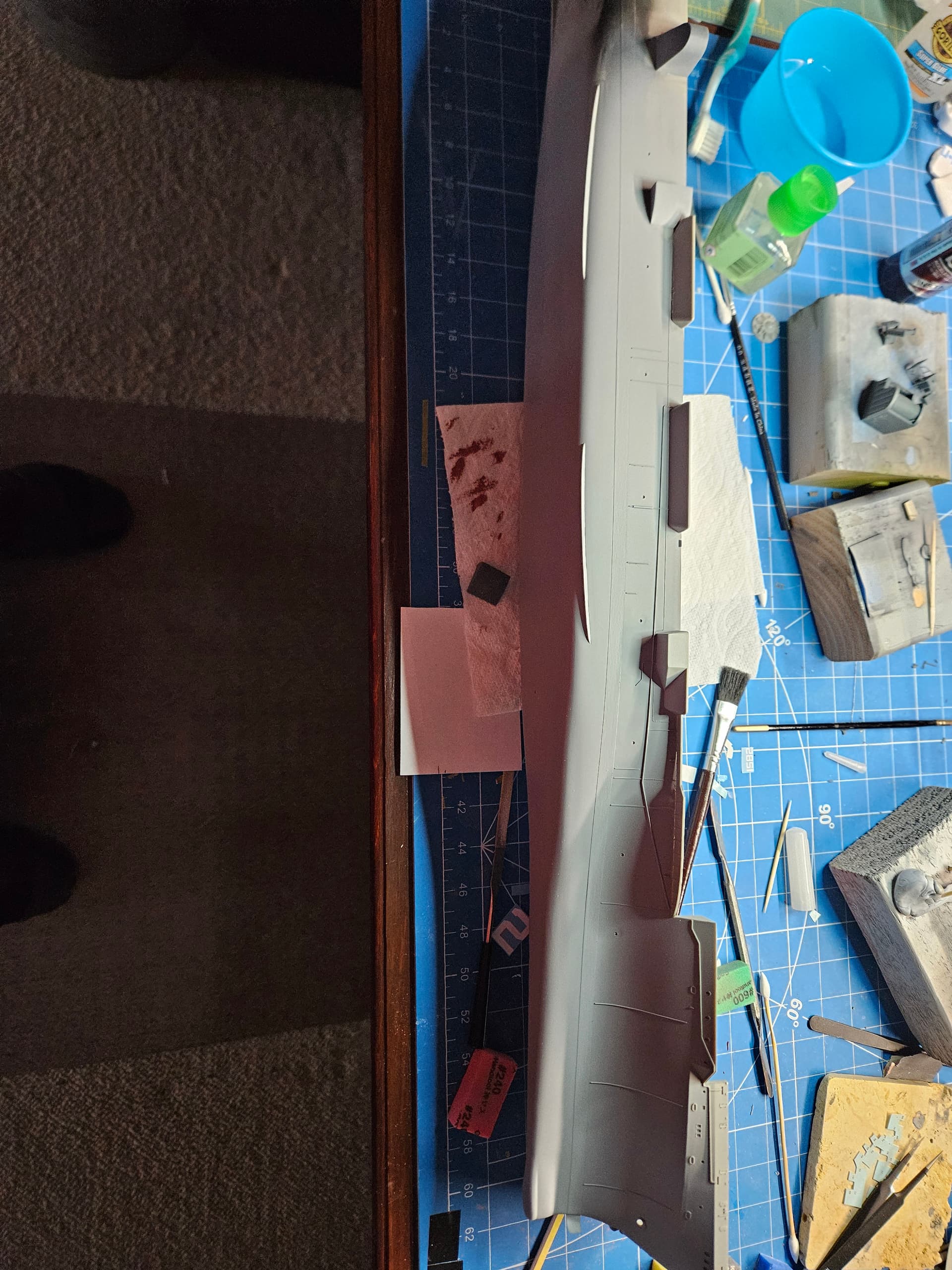
So, while I’m waiting for my custom decals to arrive for the HSS-1, I got back to doing some work on the hull of the Hornet. The unrep sponson just forward of #3 elevator is a different shape than the kit provides for the Intrepid, since the #3 elevator is much further aft on the Intrepid. Therefore, I had to cut the sponson and get it to fit around the forward elevator sponson. I have it glued in place now and will fill the gaps with CA and putty once it sets. I also primed the forward 3/4ths of the hull mainly to check the fit of the sonar dome and to get ready for painting the lower half of the hull.
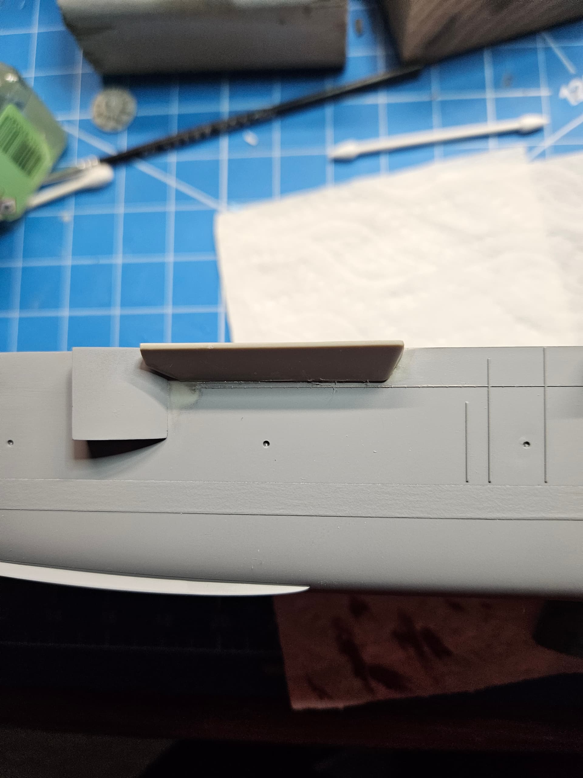
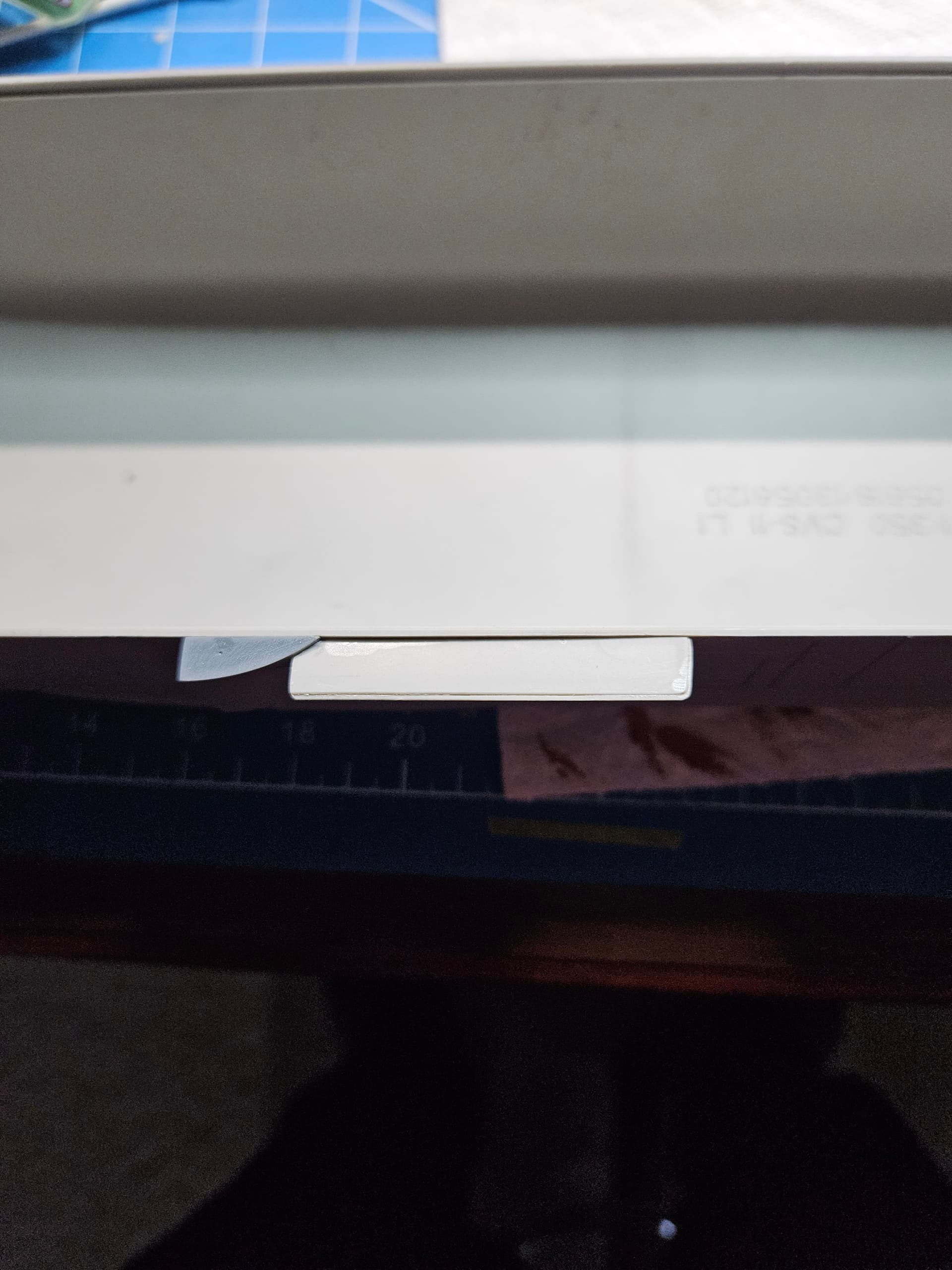
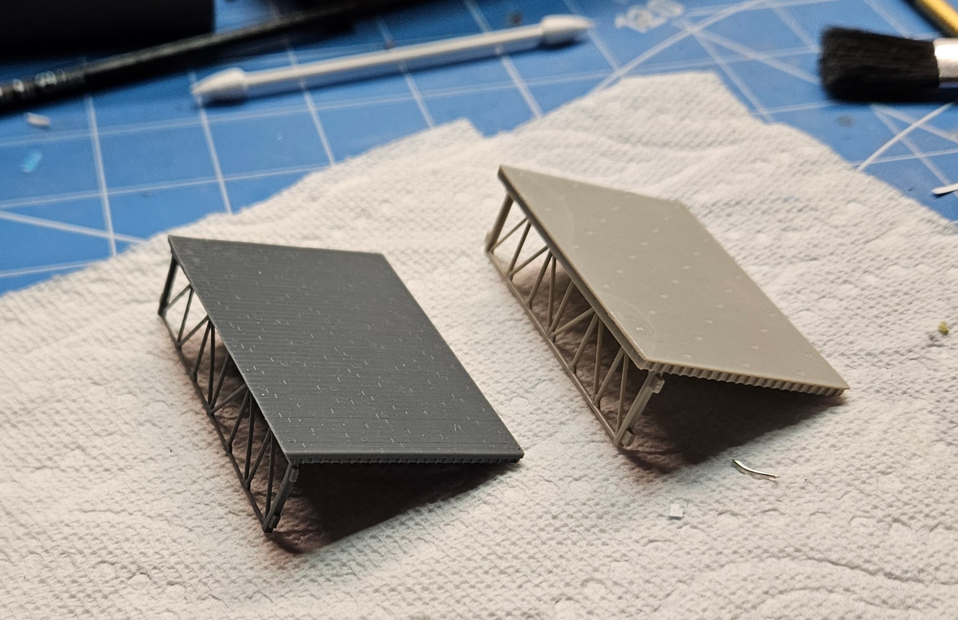
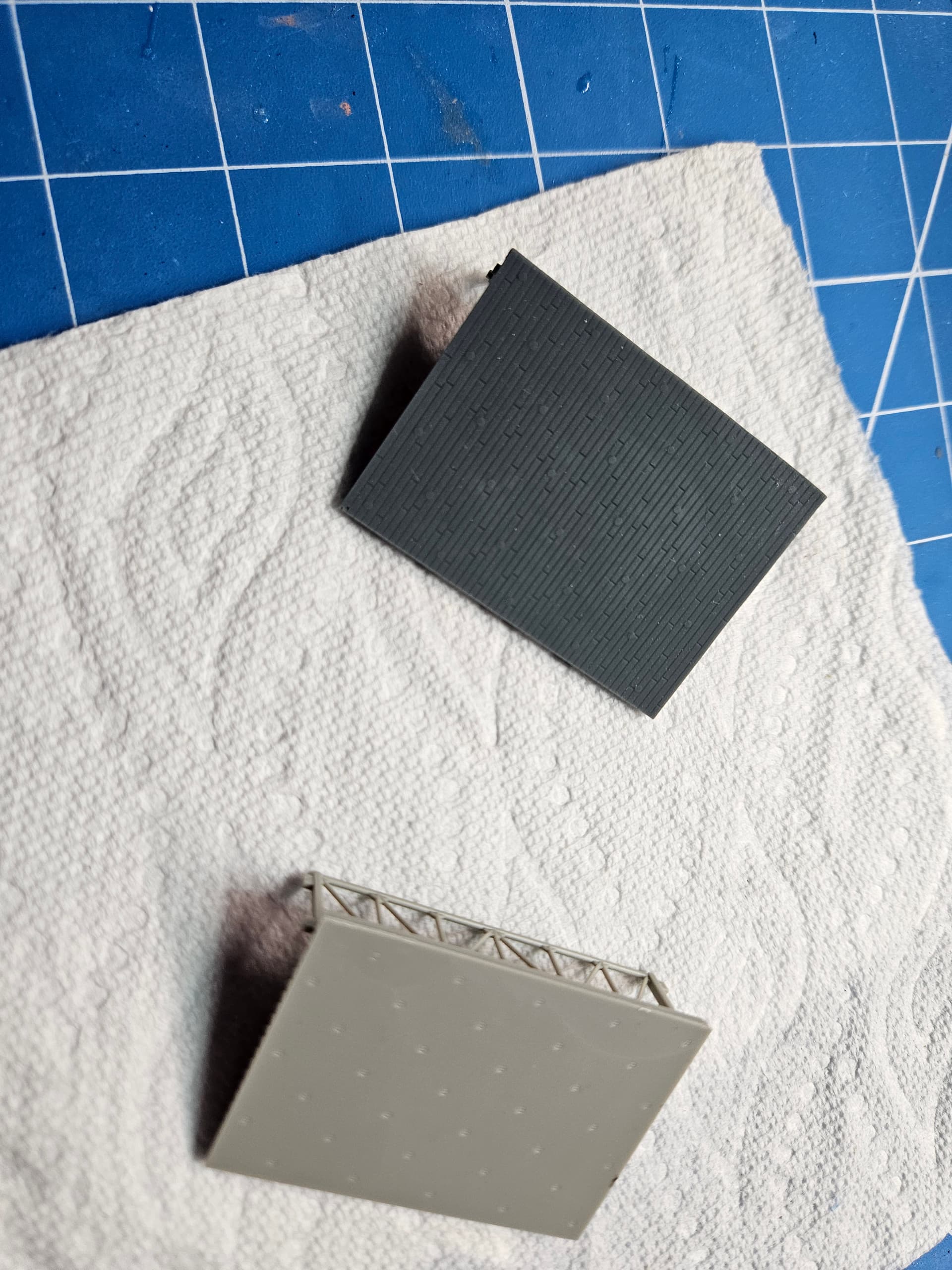
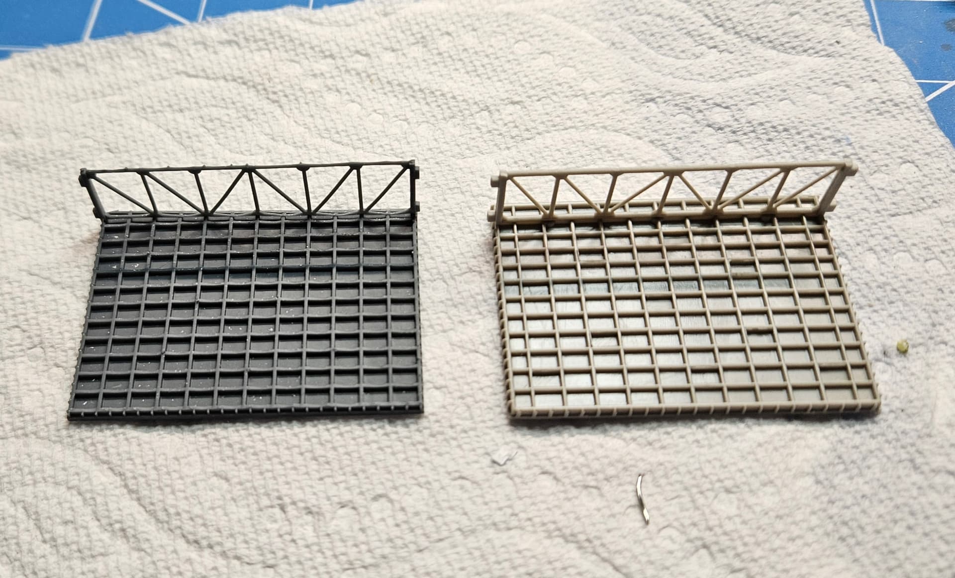
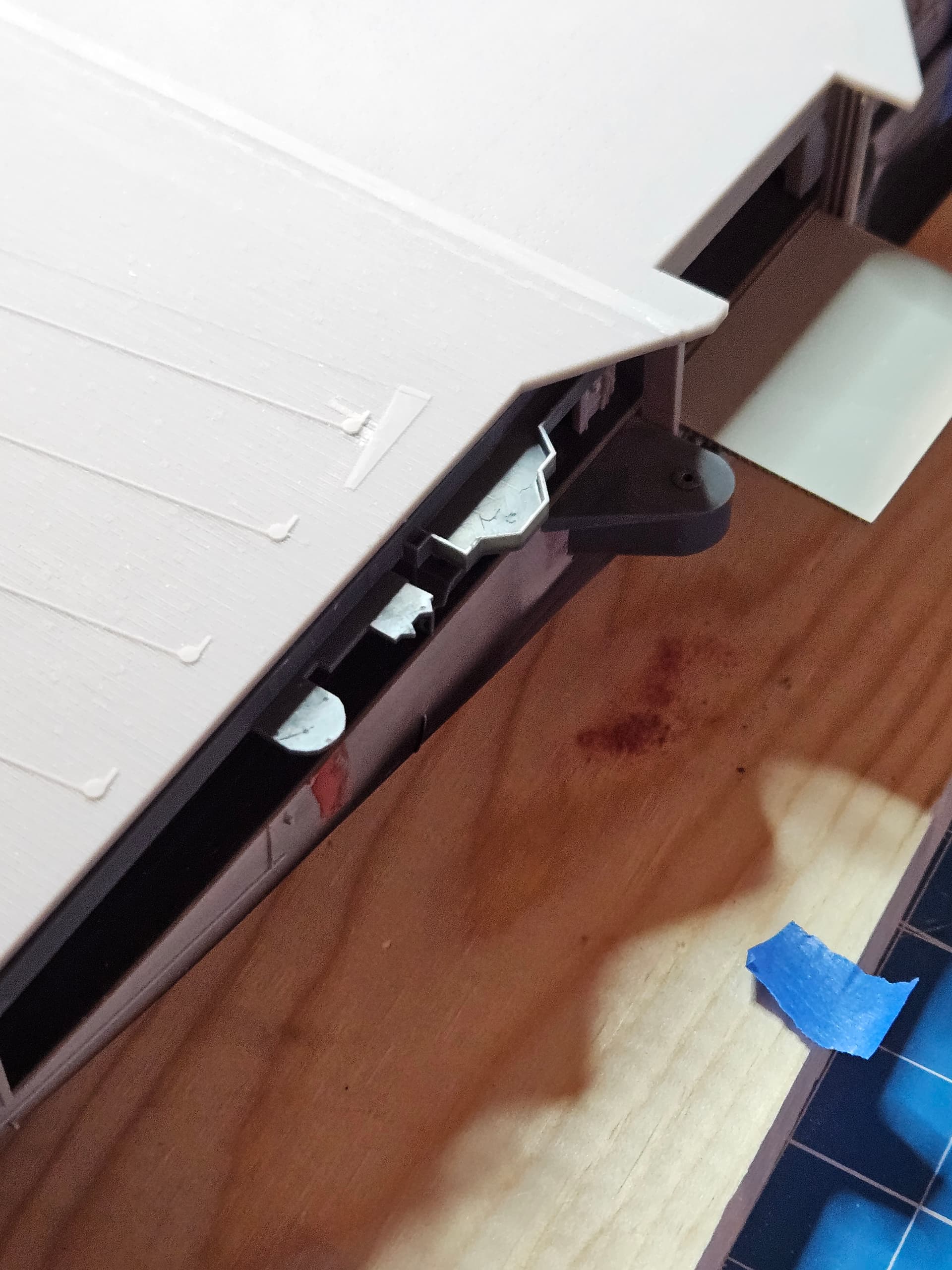
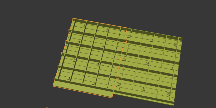
Another small issue I noted during my research was that the elevators on the Hornet during this period were planked with wood just like the rest of the flight deck. There was some thought that they might be metal, but I confirmed through cruise book photos that they were definitely wood. Rather than try to scribe the planks on the existing elevators, I opted to make 3D printed versions of them. I just printed the #3 elevator and you can see it next to the kit version. I’m super happy with how it turned out.