Bandai 1/72 Defender Destroid

Joining the contest with Real G! Thanks for mentioning it!

I’ll be doing yet another Destroid from the Macross universe. Honestly, I do have more than just Macross kits in my stash. They’re just some of the oldest ones I have. :slight_smile:

boxart

This time it’s the Defender. I plan on making a non-canon modification. The center panel on it is a clear plastic part meant to be a sensor array. The 80% of the area behind it is simple blank plastic.

stuff

The area circled in green is the sensor suite. The yellow circle is just blank space.

The plan is to remove the section circled below and build a pilot’s seat and a pilot.

illustration

Don’t know if I have time to do it all but I’m going to give it a try.

5 Likes

PG, please do not melt anything! [:P] But if you do… I have spare parts. [:D]

Glad to see you throw in! But hurry Star Force, there are only 52 days left!

ROFL!

I’m hoping not to have to visit Real G’s Parts Shop this go around. [:P]

As for the deadline. I either make it or I don’t.

Regardless, my goal remains the same. Have fun and learn something new. :slight_smile:

Hit the ground running on this project.

The plastic of the cockpit area is oddly brittle in places. When trimming some of the sprue with a new blade it broke off in chunks rather than shaving neatly.

brittle

Thankfully nothing that can’t be fixed, but something I’ll have to look out for going forward.

Scribed around the panel area where I want to build the cockpit. It came out suprisingly clean. Practically no clean up needed.

panel

Flipping the panel and going to use it as the floor for the cockpit since it’s a perfect mirror.

Taped it into place for a dryfit.

floor

Hopefully that will save me some work.

test pilot

Intial test fit with the pilot worked well!

Something I noticed is the cockpit entry hatch isn’t exactly aligned to the seat. Perhaps it lays back for entry/exit. :slight_smile:

hatch

Started roughing the layout of the cockpit. Getting a feel for the space and how to use it.

layout

Will need to add a panel spacer at the bootom to push the cockpit tub in a little further. Otherwise the feet will keep the canopy from fully seating.

Thinking of adding some joysticks to the angled panels to the left and right of the pilot. Do some test fitting with the arms loosely attached with blue tack to get a good idea of placement.

The old friction fit joints on these models loosen very quickly so I’ve ordered some polycaps. Maybe a few of the joints can be easily retrofitted. Never done it before so not sure what that’s going to be like. It’s also going to be a couple of weeks before they arrive. Given the tight timeline they may not make it into this build.

3 Likes

Looks cool! Good luck!!!

PG I will provide as much intel on retrofitting the joints with polycaps as I can to assist you. One challenge is that the older kits often have pins that are NOT 2, 3, or 4 mm in diameter! The Queadluun Rau was maddening to retrofit!

Thanks Real G, I’ll likely take you up on that once I have the polycaps in hand.

That is exactly what I discovered with the Destroid. Most of the pins are 2.5, 3.5, or 4.5 mm. There were a couple that were nearly 4mm or nearly 5mm, but they were the exception. I ordered a wide range of sizes and types of polycaps in the hopes of finding a magical mix. My hopes aren’t very high, but I’d like to try. Even if it doesn’t work out for this kit, I’ll at least have caps available to experiment with later on.

I’ve not been idle the last couple of days.

Continued hashing out the cockpit. Decided to build the seat itself using Apoxie sculpt. Very glad I picked up a cheap set of sculpting tools. It would have been a nightmare trying to shape that seat and headrest using a toothpick.

seat

I don’t know if my batch of Apoxie sculpt is old or if it’s normal but both compound A & B are rather dry and need a fair amount of water added to make it supple and workable.

I extended out the front of the seat with more Apoxie sculpt so the legs would look fully supported. I’m debating if I want to go so far as to try and build out foot pedals.

I think the chair is coming along nicely. I’m going to punch out some small bits of styrene to use as buttons on the sidepanels. Next up will be aligning the pilot’s arms. Once thats done I’ll know where to place the joystick controls. I’ve got some very thin brass that I’ll likely use for those.

The pilot isn’t the only one getting attention. The cannon barrels have been assembled cleaned up and primed.

barrels

You might see a slight step in the larger barrel bands. Interesting fact, that isn’t a mold seam. That is how they sculpted the bands. They did left/right halves so the seams are at the top and bottom of the barrels. Which thankfully look to be invisible underneath the primer. :slight_smile:

Started assembling the main part of one of the cannon housings. This may turn out to be a mistake from a polycap retrofit perspective, but with the limited time for the build I don’t want to hold up everything while waiting for the polycaps to be delivered.

housing

1 Like

She’s coming along well Phoenix, nice work on the cannons and pilot!

Continuing to build out the cockpit. Added the sides to the tub. Unlike the my Destroid Spartan, I haven’t created any templates for building the cockpit. This one is figuring it out as I go along

Traced the panel I cut out to define the upper curve of the cockpit wall. It also lets me use it as additional support for the canopy.

wall2

sidewalls

Now those tubes there look made for LED lights. Especially since the far end will be capped with a clear lens.

Seeing what Bakster has done with lighitng his models makes this one look like a cake walk. And the lighting he installs really adds to the piece.

So lighting this model has been on my mind since I saw those holes leading to the headlights. Earlier this week I decided to pull the trigger and order some small pre-wired 3mm LEDs in an assortment of colors. I don’t know enough about how to properly select the resistor for a given LED so this seemed like an easy way to have them ready to go with minimal fuss.

The LEDs were delivered this weekend. They came in unlabled baggies so they needed to be tested and sorted.

Broke out the good old breadboard I use for testing out arduino circuits. I’ve got a bunch of 3V CR2025 buttoncell batteries hanging around. They’re nice and compact so I figure they would make a good concealable power source.

breadboard

Wasn’t certain of their brightness so tested them at both 3V and 6V.

Here it is wired for 3V.

3v

And the same light wired for 6v.

6v

These little LEDs are bright at 3V but nearly blinding at 6V. So if I go with installing them it will be at 3V.

To get an idea of what it could look like installed I stuck the lights on the outside

outside light

And powered them up at 3v.

headlightsThat could look really awesome. Even at 3V they practically blind the camera.

However, it’s going to take time to figure out installation and power placement. There’s room for the buttoncells inside. Barely.

testfit

If I go this route there won’t be a way to change the batteries, but it would be 100% portable, last long enough to take photos for the contest, and it’s not like I’m planning on having the lights on all the time.

I’m likely biting off more than I can chew with this build. So far everything but the pilot tub is still 100% optional. Pretty soon I’ll have to decide just what I am going to implement. There isn’t a bunch of time for dallying around.

2 Likes

The addition of lights to this model has effectively consumed my thoughts for the last couple of days. Mostly likely because the addition of a couple of lights to this model is comparatively easy. Making it an excellent gateway drug to electrify future models. [:D]

My recent hangup was power. I really didnt want to have a set of unchangeable batteries stuck in the model. Effectively making the lighting a limited engagement gimmick. Also I was getting stuck on where to place a switch.

I had originally wanted to store the batteries inside the model without leaving an external physical trace. But if I am willing to cut out the the plastic under these cowlings.

cowling

I should be able to fit the battery in there. The cowlings have a nice pressure fit so they can be put in place and removed easily to change batteries if needed.

batterycompartment

Found the perfect button for it in my stash.
button

It’s only a couple of mm long. Got a bunch of them from when I was repairing an old DVD player.

It will make for a great hidden activation right behind the cowling.

buttonscale

However I am not mounting it there. It will actually be mounted behind. The button itself is just slightly taller than the thickness of the plastic which is about .041". The button is .045" high and activates at .041". It was like it was designed for this purpose.

I drilled a small hole and inserted the button to verify fit. Turns out the plastic was slightly thicker here so I had to file it down about .004" to so the switch could activate.

button placement

This is how it looks from behind. I don’t have any epoxy on hand so am thinking of encasing it in Apoxie sculpt and securing it with a couple of small machine screws.

buttonback

I’ve got the wiring diagram ironed out so next steps is to start cutting out the panels under the cowls and soldering on the leads. I’ve got a spool of kynar wire, which is a very fine gauge wire, leftover from another electronics repair I did. It’s similar to magnet wire but instead of being enamled it has a very fine plastic sheath. Very easy to work with.

Still waiting for the polycaps. I’ve not yet written off trying some polycaps, but if they don’t arrive soon I’ll just have to go with the OOB joints.

1 Like

She’s coming along great!!! Nice work on hiding the batteries and switch.

Gosh, this is the third time I’ve tried to open this thread…

Thanks Gamera!

I feel good about the solution I came up with. So far all the test fits have been good.

An unexpected side effect of this is I am having to adjust my normal paint/assembly process to account for these changes. I don’t think it will slow me down much.

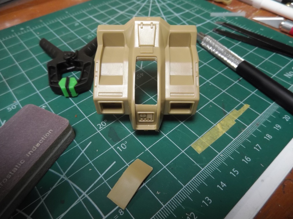
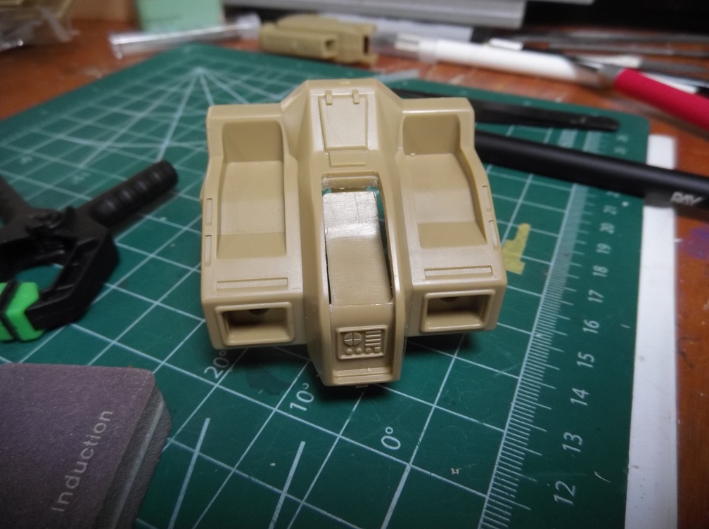
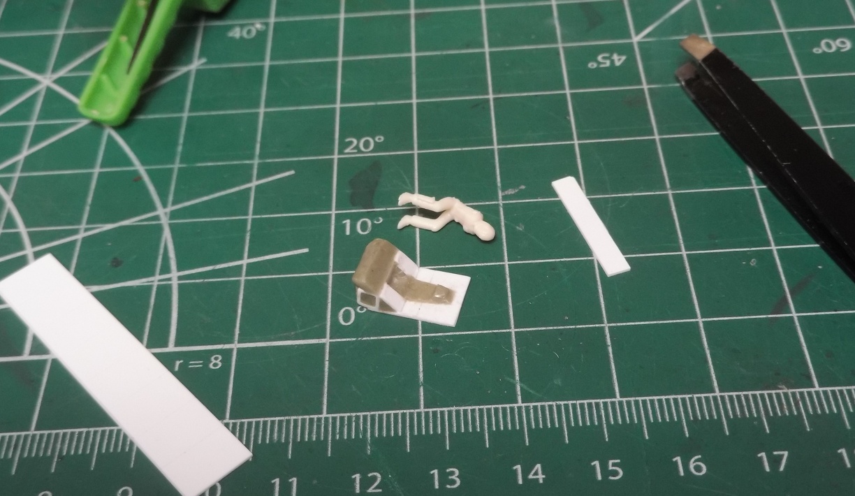
I wanted to make sure I left a little bit of a lip all around the area for the cowling to rest upon. To do that I made this little jig out of .020 styrene. It doesn’t have to be exact so the slop in it doesn’t hurt anything.

jig

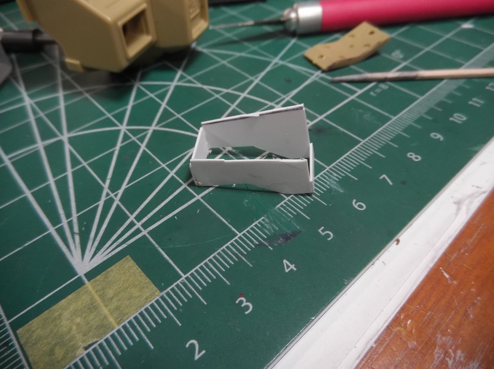
I had to cut the bottom to conform to the the shape of the shoulder to make it easier to scribe the lines.

jig in place

As you can see my workbench is still a mess. I seem to naturally lean towards chaos in my workspace. :slight_smile:

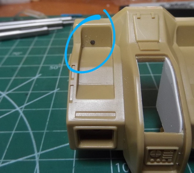
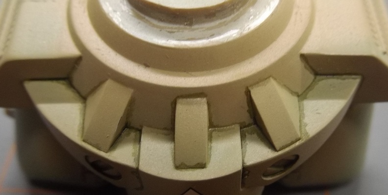
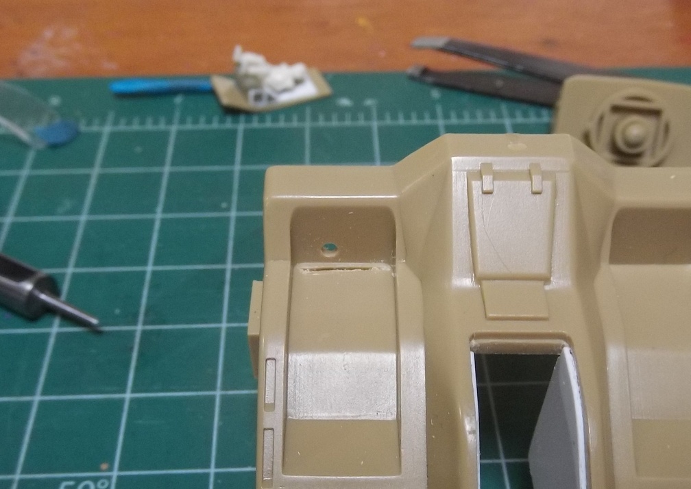
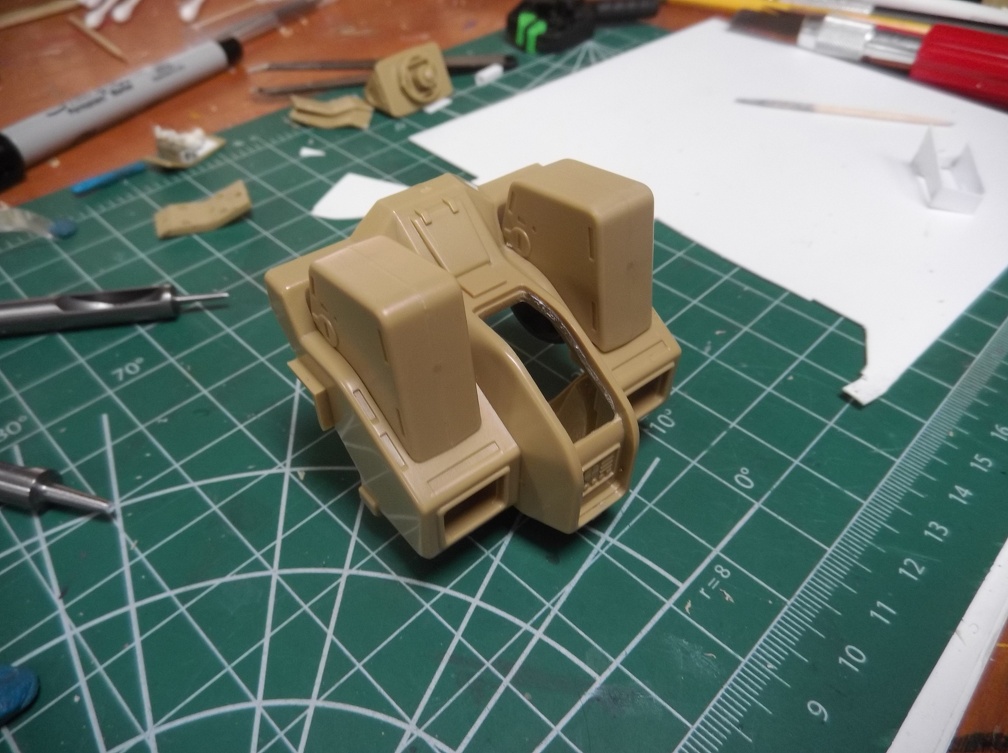
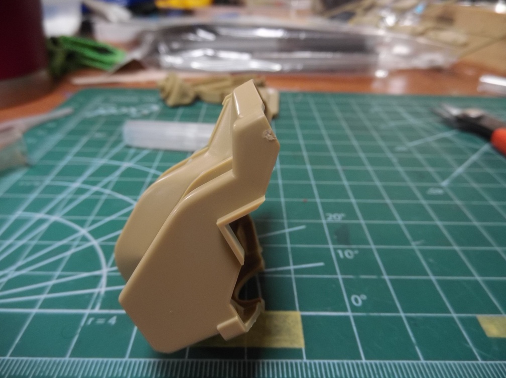
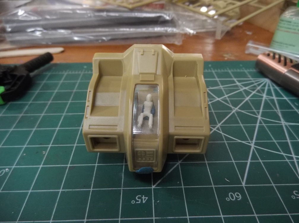
Quick check of the first section scribed. Yup there is a lip present. Success!

test and check

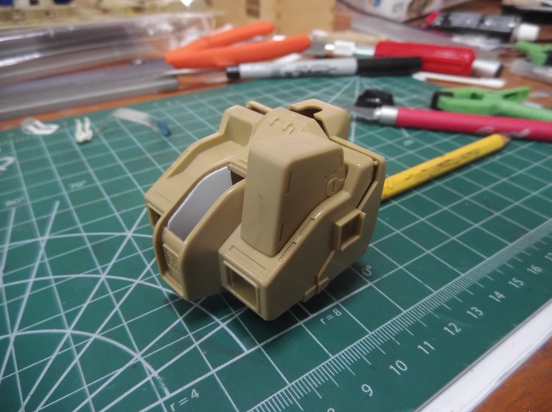
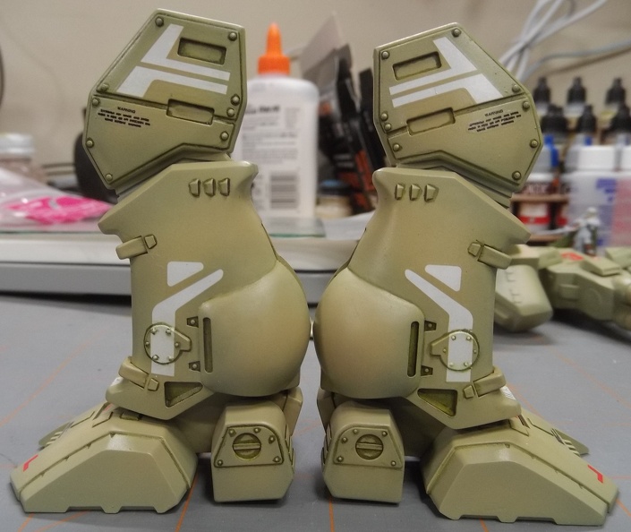
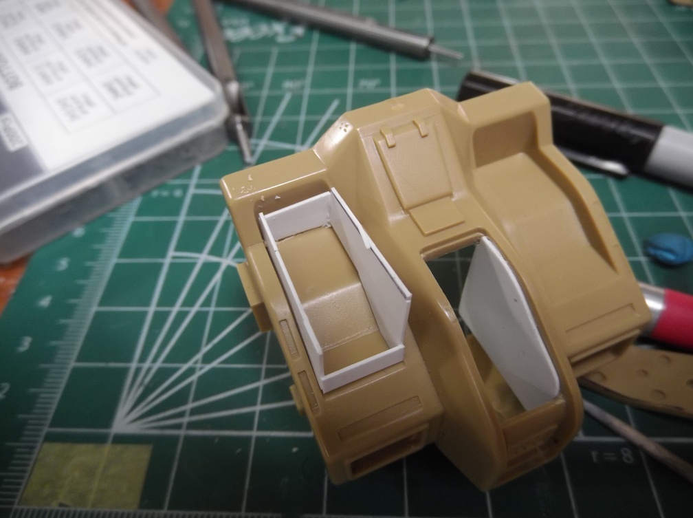
And just like that, one shoulder is done and ready to test fit the battery compartment.
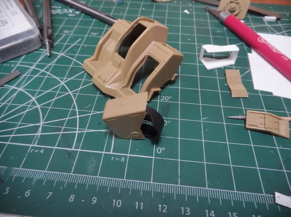
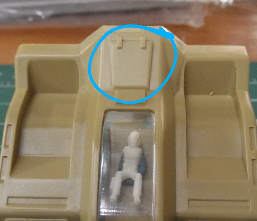
test fit battery

batteryfits

Looking good!

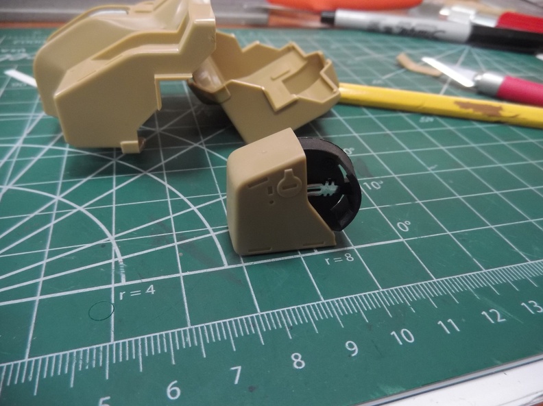
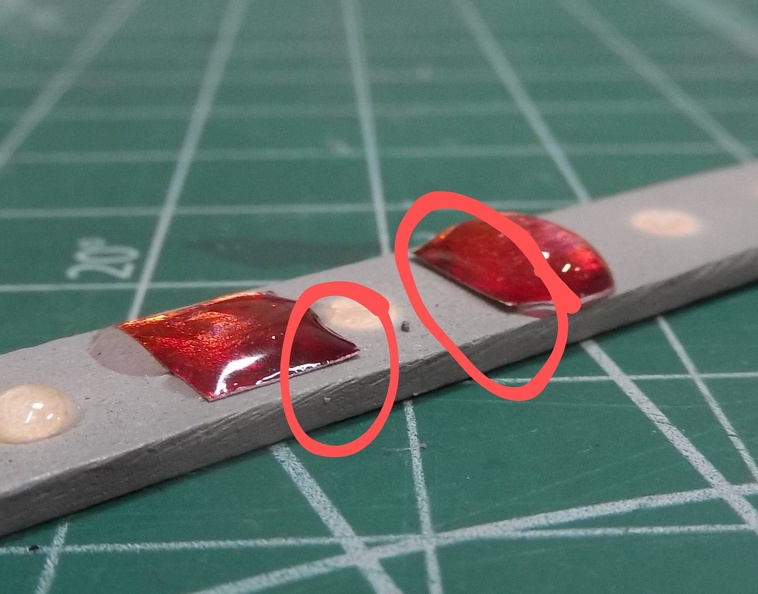
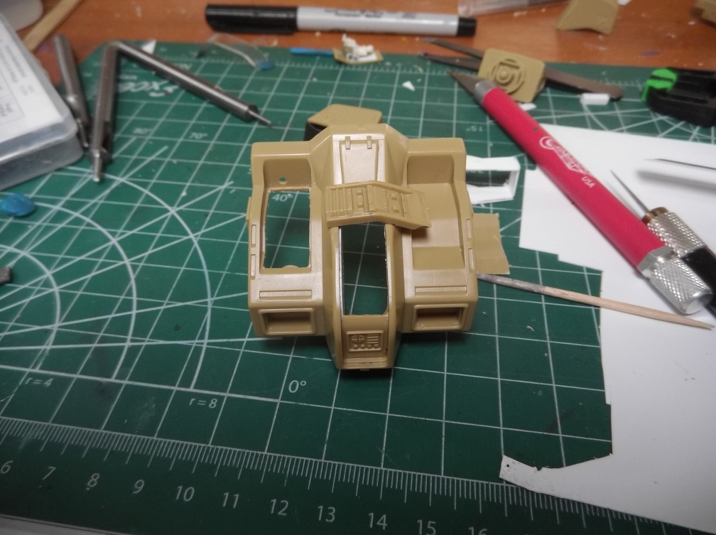
And if in the end I give up. There’s these lovely little plates that can cover the holes. The other reason I wanted a lip.

plates1

plates2

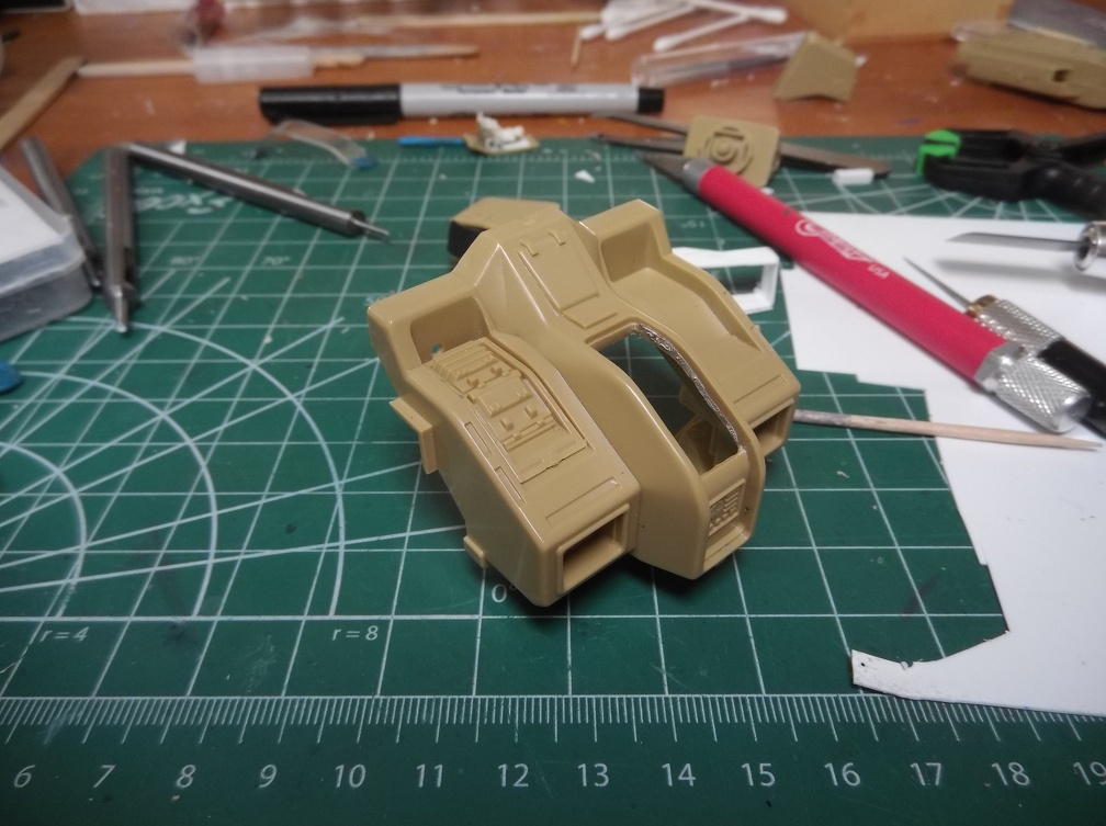
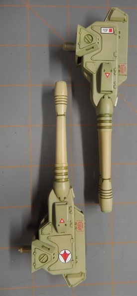
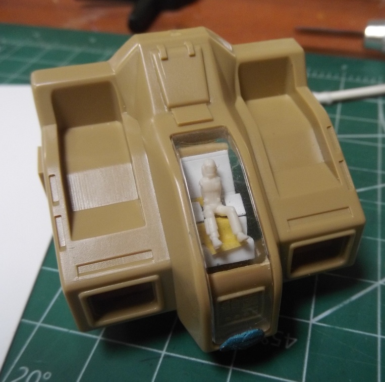
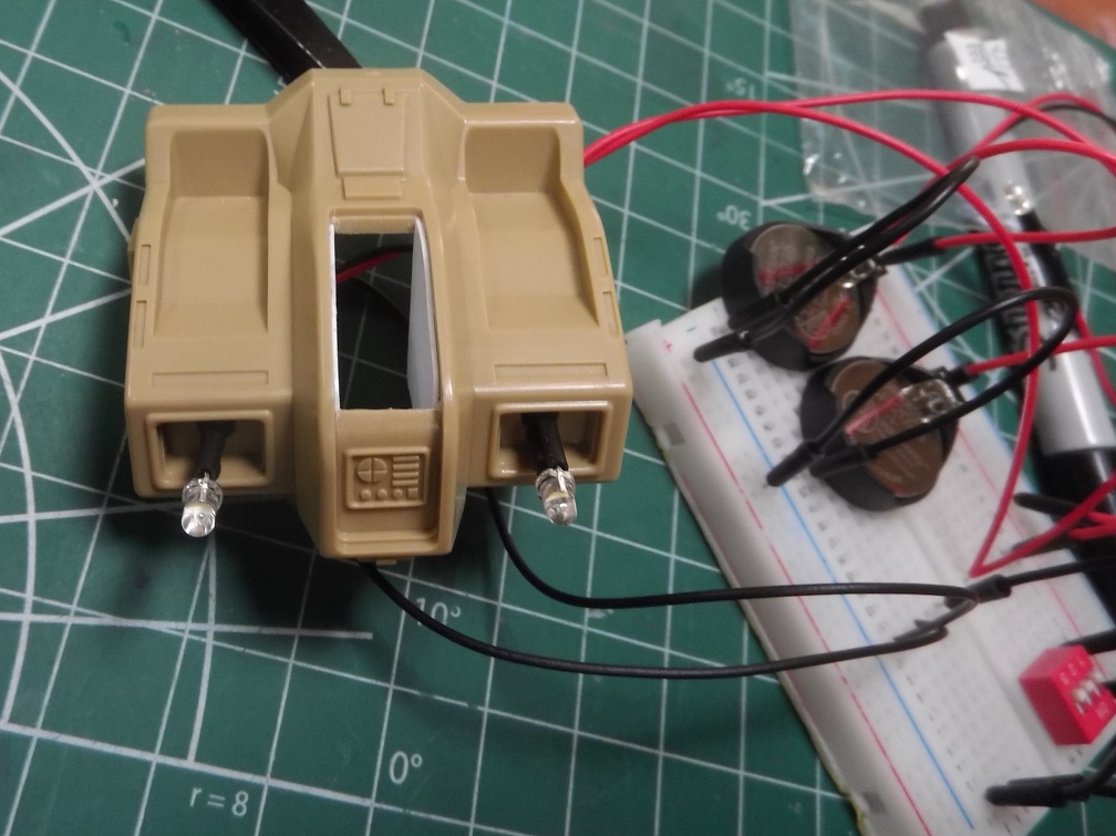
How it looks with both cowls in place.

cowling

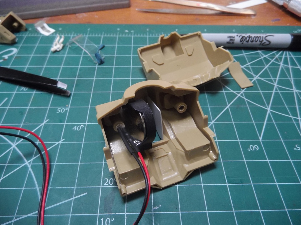
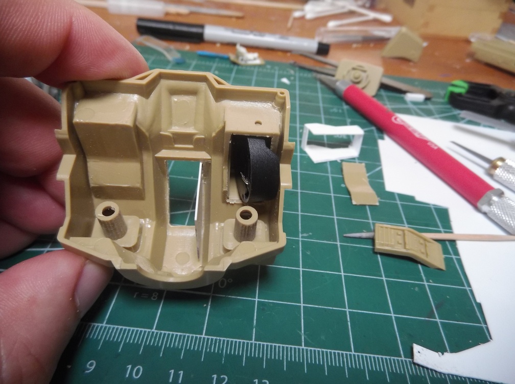
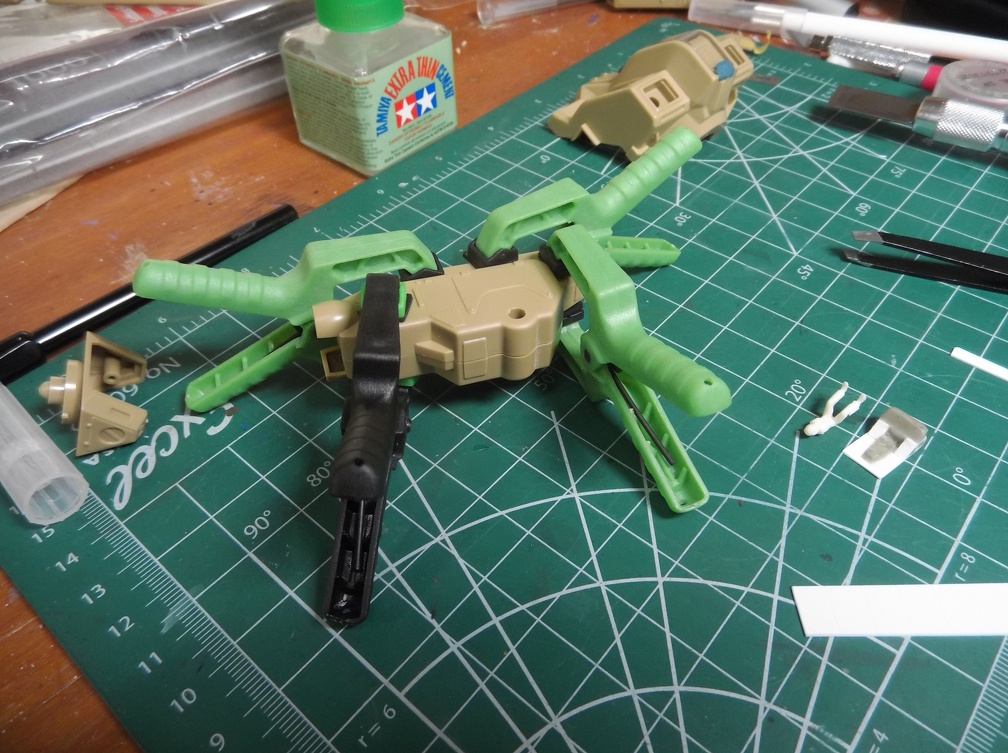
And hidden underneath the cowls, the battery holders!

batteries and cowls

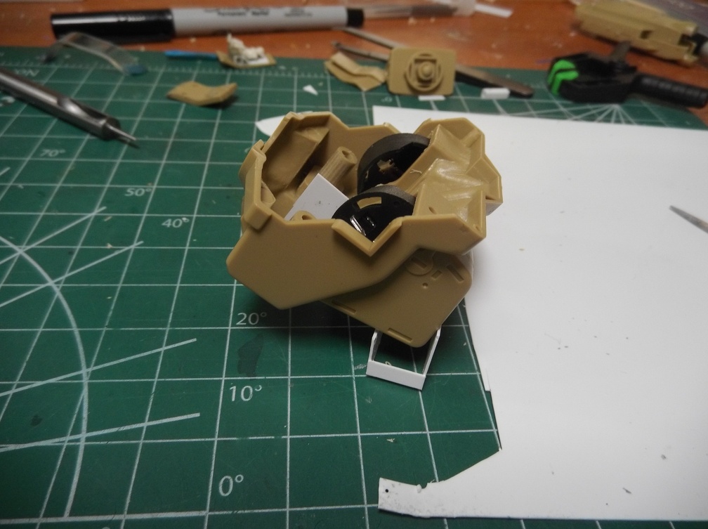
It will now be possible to store the batteries in the model and change them by lifting off the cowling. The battery clips are simple pressure fits so they’ll be easy to put in and take out.

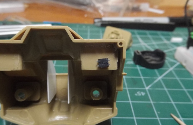
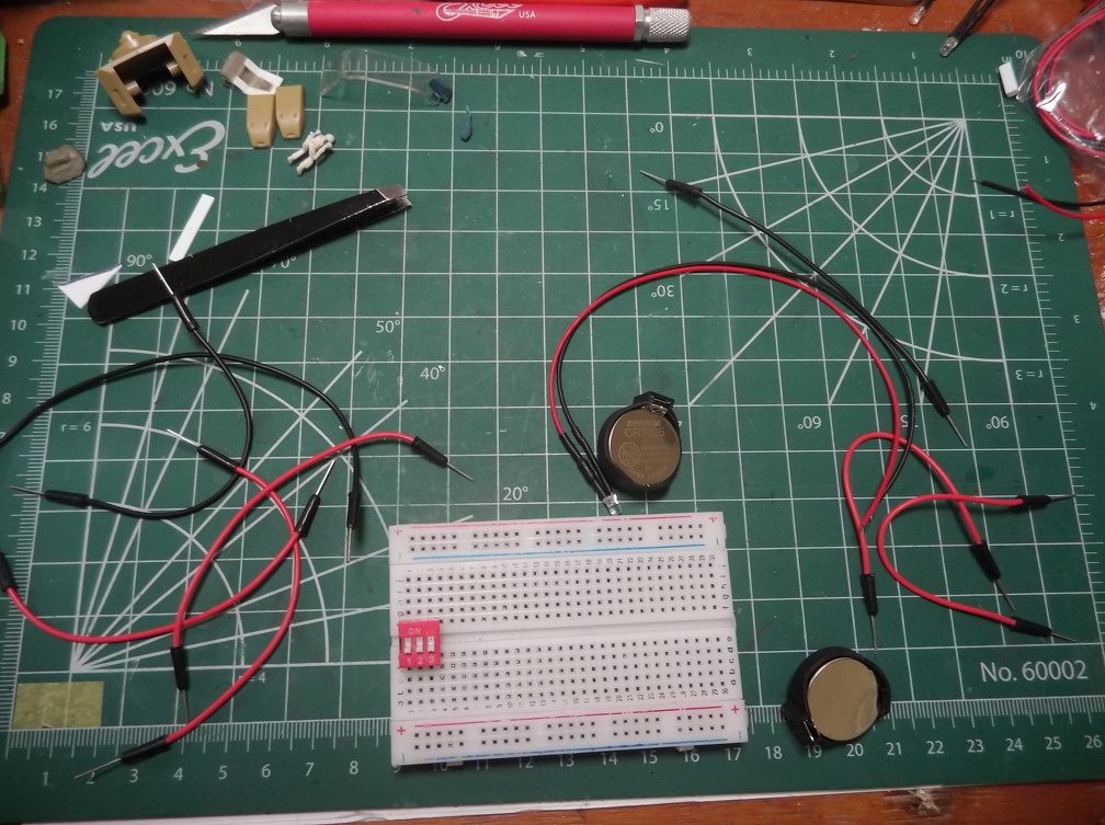
Prep for soldering everything together.

prep

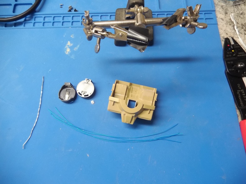
The kynar wire is the blue strands. It’s very fine, very flexible, and easy to solder.

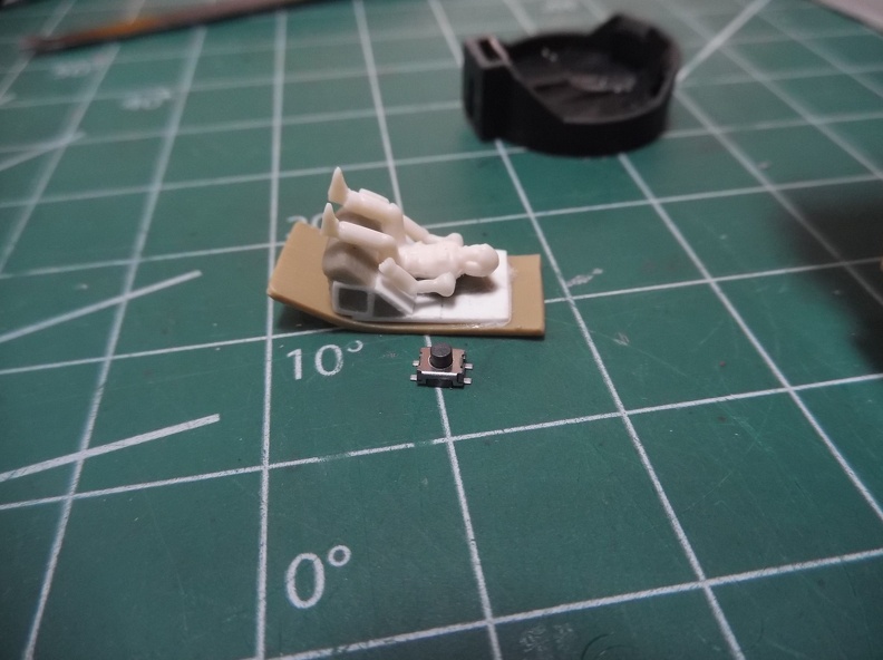
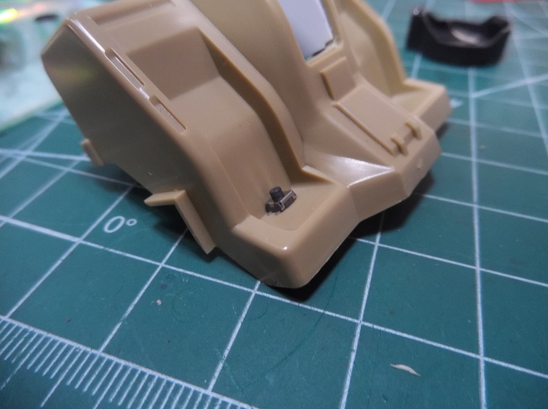
This should help with a sense of scale.

The tip of my soldering iron is larger than button!

soldering bits

No worries though. I’ve had lots of practice soldering small items when refurbishing Sega Game Gear portable consoles.

button complete

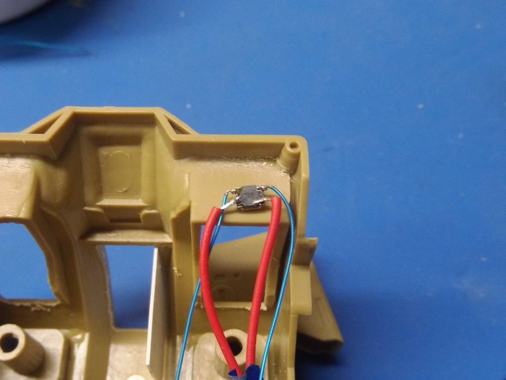
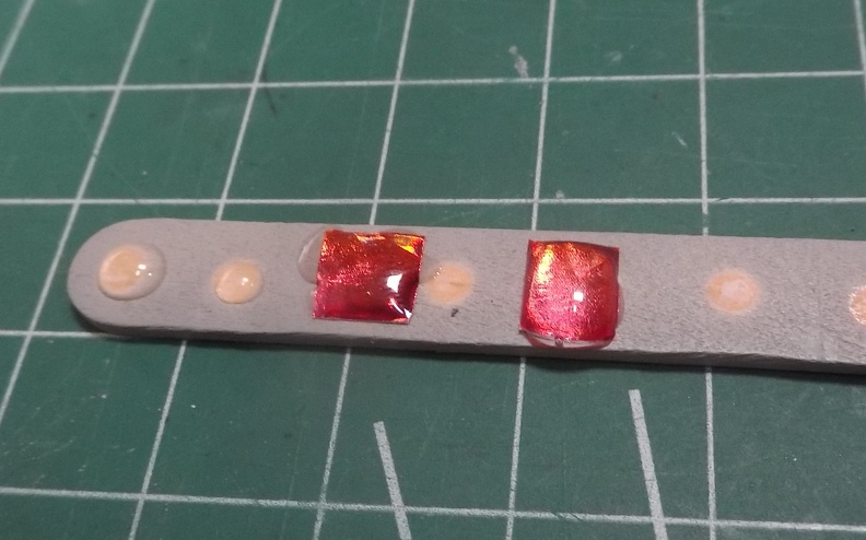
the blue kynar wires go to the positive terminals of the battery clips, the red wires are the positive leads on the LEDs. I’ll be wiring the negative leads of the LEDs directly to the negative pole of the battery clips.

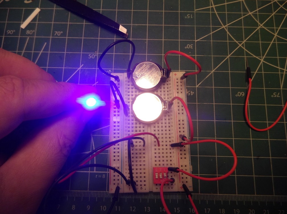
I tested the button and it works!

Then I noticed I soldered in the wrong color LED.

ROFL![:D]

No worries, it’s an easy fix. Just a couple of minutes of work to take care of. I’m thinking of adding a light to the cockpit and perhaps seeing if I can backlight the sensor array.

Depends upon my ability to secure the lights and the amount of space to accomodate them. Once that’s ironed out I can add the screws to hold the button and then encase it in Apoxy sculpt. It will help secure the button and also ensure the leads don’t accidentally break off of the switch.
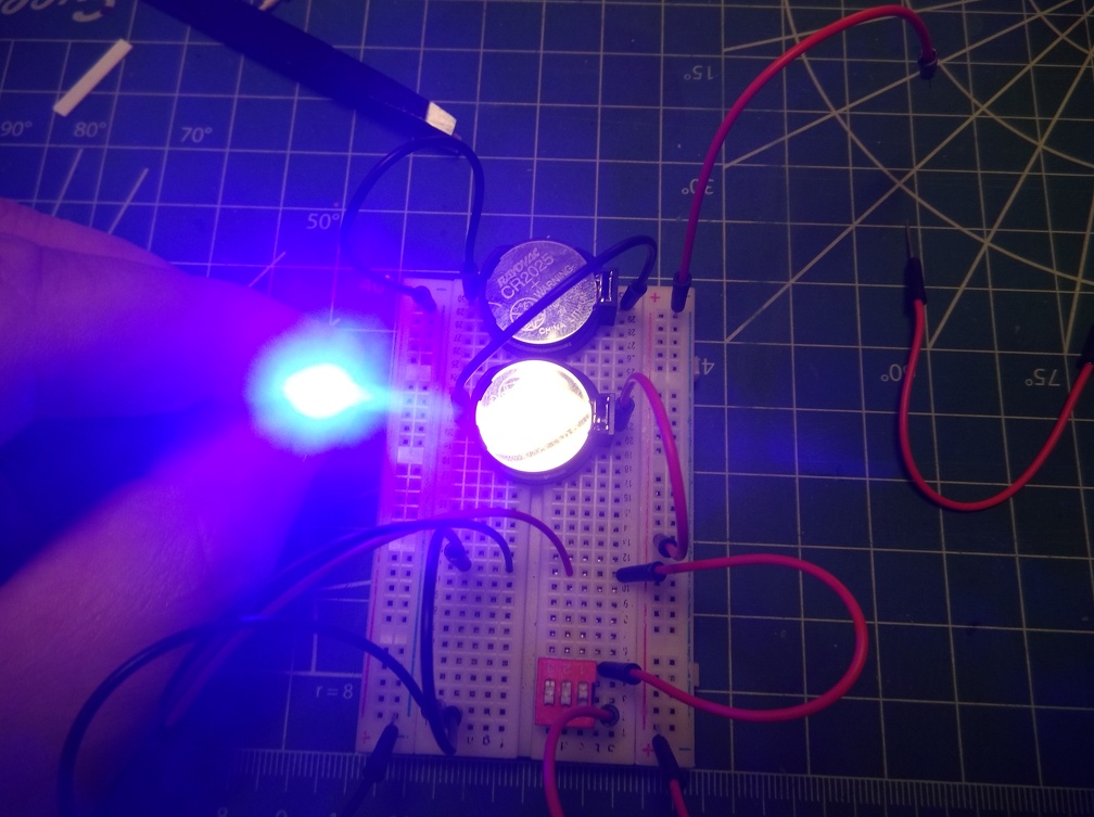
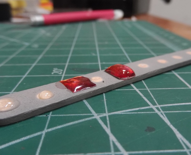
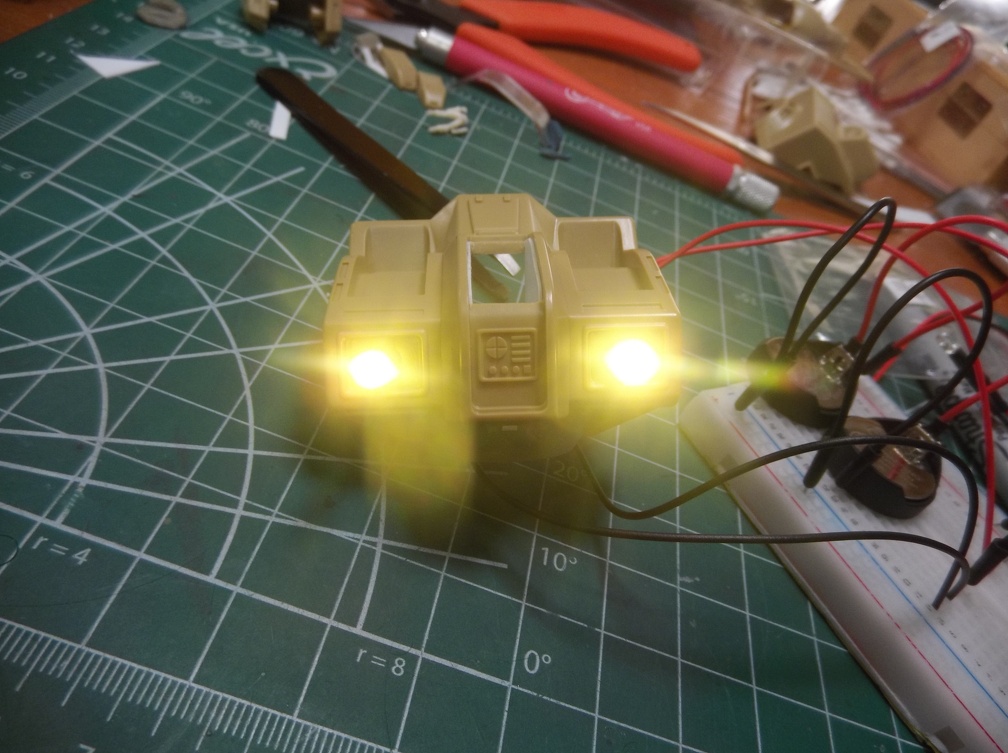
2 Likes

Hooray, the FSM toilet is working again! Those spambots must eat a lot of spicy, greasy buritos! I was shut out since last week and kept checking back to no avail.

Anyway, great progress Phoenix G! Tucking the batteries under the ammo packs was a great idea. I also dislike wires dangling from a model. I think only Evangellions can get away with it since they have those Tesla supercharger cords!

Looks good! All the extra work you’re putting in there is sharp! [Y]

Wow, the forum is back! There’s been a lot going on with this kit since August. It’s still a WIP. I started posting it on the MSC forum recently so if you want to get caught up you can see what’s happened to it by visiting the the other thread.

https://modelerssocialclub.proboards.com/thread/17456/bandai-1-72-destroid-defender

Here is a teaser of current state.


2 Likes

Fun project. I have one of these but mine will end up being a Rifleman from the Battletech universe. Just need to figure out if it will be a House mech or a Merc.

1 Like

It has indeed been a fun project. A bit challenging at times due to the quality of the fit, but more fun than frustrating. Hopefully will get to see your Battletech version of it.

At the moment I’m doing the pin wash. Working on the second color. Will have some pics to post soon that will hopefully illustrate the differences.

Had some paint wicking when working on the joints

Apparently this area did not receive a good gloss coat. I touched the brush to it and watched the paint ooze outward. It cleaned up ok, and thankfully this spot is right under the torso so it won’t be very visible when on display.

That’s all the pictures of that for now. I figure there’s been enough about panel lines and pin washes for now. :slight_smile:

I am experimenting with something I saw another modeler do using something called Rapie Tape (a metallic tape color tape) and clear resin to create a colored lens for a Gundam Hazel Custom. It’s a neat build, recommend taking a look at it.

modelerssocialclub.proboards.com/post/426844/thread

I really liked their method.

Couldn’t find Rapie Tape in the states, but Washi tape is readily accessible and has lots of metallic colors so I picked up a sampler pack for something to experiment with in the future. Apparently the future is now because the more I thought about it the more I was certain there is a place or two on this model it would look good on. Apparently I am a sucker for punishment because here I am again, trying another new thing on this build. Oh well! Let the testing begin! :smiley:
I picked up some UV Clear Resin on the cheap a while back after seeing the amazing things people have done with it. It has since sat in its box patiently awaiting its turn. And its turn is today! Well, the day before yesterday really, but that’s not important.

For a quick test, I placed two dollops (that’s a technical term there) of differing sizes on a popsicle stick to see how well it retained shape and how quickly it hardened. Color me impressed. It poured easily, retained shape quite well, and resisted scratches right away. No wonder this stuff is so popular! Now I wanted to see how this washi tape looked with a thin coating or thick coating of resin on top.

On the same popsicle stick applied two similar sized pieces of tape. The left one has the thinner coating and the right one has a much thicker ball.

I wasn’t being particularly neat. I was more interested in seeing how the tape looked through it. And it looks good. I find it interesting how the refraction of light changes the perception of color.

I deliberately put a bigger blob of resin on the far right. Wanted to see how it changed the light passing through. It is definitely brighter and lighter looking.

There is also shrinkage when it cures. It is slight, but it could cause problems. Observe the circled areas below.

You can see the resin shrunk as it cured and lifted the edges of the washi tape. That’s a problem. Conceivably the whole thing could pop right off! Could this be addressed by carefully laying the resin just slightly wider than the tape?

How to do it cleanly…

Is it possible to mask cleanly and effectively around resin?

I see more testing in my future. :slight_smile:

3 Likes