Another 1/96 USS Constitution - third time's a charm (I hope)

Hi James,

Thanks for the offer, but actually I have a bunch of crewmen from my two previous builds of the Constitution, along with a set of crewmen from the Cutty Sark in my stash, plus a handful of crew from the 1/96 Mayflower in my stash (probably won’t be using the Pilgrim figures, though). So I actually have roughly 115 crew figures in 1/96 scale. Unfortunately, the Crewmen from the constitution are in similar poses, so if I choose to use them, I will need to find creative ways to make them look different. If I choose not to use them, they are yours. I am actually considering now a water diorama with the ship under sail, with as may of the crew as I can muster.

Best,

Jose

That’s awesome Jose,

My casting and molding kit is, on it’s way to my modeling table as we speak.

So I’ll, be cranking out little dudes shortly. You wouldn’t happen to know the exact proper number or round about of how many crew we’re on deck during beat to quarters do you?

I’ve installed the fore channels with the stropped deadeyes and chains._DSC8072 by Jose Gonzales, on Flickr

I apologize in advance for the wordy descriptions following - you can skip it and just enjoy the pics.

Stropping the deadeyes

The lower deadeyes are 5/32 inch diameter. I tried to strop the deadeyes according to the link listed a few posts up, but did not follow it to the letter by a longshot. Mistake number one - instead of copper wire, I bought K&S 0.020 brass ROD. Yes, the differrence between rod and wire were not apparent to me. I clamped the rod to a 1/8 inch dia brass tubing_DSC8086 by Jose Gonzales, on Flickr and wound the rod tightly around the tube, to form tight coils which I would then snip through to form rings. I discovered, however, that no matter how tightly I wound the rod around the tubing, upon releasing the end, the rod would spring outward and the coil was much larger in diameter than the 1/8 inch I intended. I plugged on, snipped through the coils_DSC8087 by Jose Gonzales, on Flickr

and soldered the rings closed._DSC8087 by Jose Gonzales, on Flickr

I pinched the annealed spot between a 5/32 inch dia drill bit and a ruler with a rounded notch along the center, and pinched the ring around the drill bit._DSC8089 by Jose Gonzales, on Flickr

95% of the time, the solder joint snapped, and I had to re-solder the joints after pinching. The stiffness of the rings, the fact that I used cheap tin-based solder, and the softness of the ruler’s wood were probably all contributing factors.

After shaping the strop around the drill bit, I snapped the deadeyes into the strop, and pinched the stem of the strop as close to the deadeyes as I could, but for many, the strops again snapped at the solder joint. In the end I ended up repeating the process for all deadeyes, but switched to 0.016 brase WIRE, which I found to be much more malleable. Note that I added a bend in the strop - the chains below and the deadeyes above will be at opposite angles relative to the channels._DSC7869 by Jose Gonzales, on Flickr

The Channels

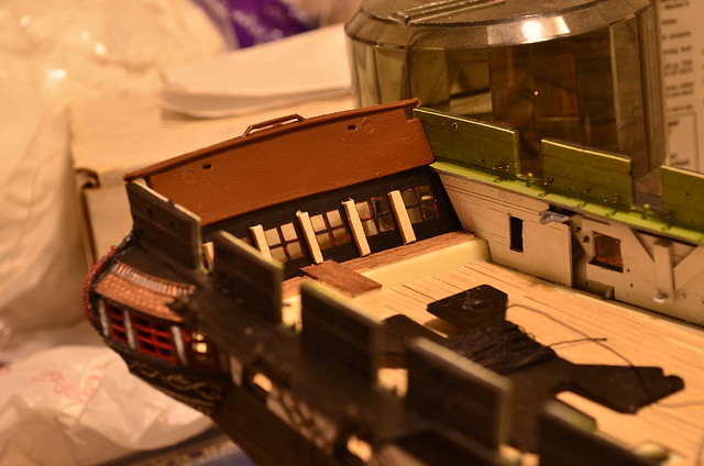
The Bluejacket kit comes with a strip of wood specifically intended to be used to form the channels. I was planning to create 2 sets of channels, one from the wood from the Bluejacket kit, and one made from the plastic parts of the Revell kit, and then go with whichever one I liked better. I used the plastic channel as a template for the wooden one. Upon carving the basswood, I found a few things. 1. Wood is a lot harder to carve than plastic. 2. wood is a lot harder to carve than plastic. I got the feeling that no matter how much I carved the wood, it would be hard to get the inside surface of the channel to match as perfectly as the plastic one already does. I was planning on inserting brass rod into the wood, drilling matching holes through the hull, and attaching the channels, but in the end, I decided that no matter how well I carved the wood channels, the join between them and the hull would not be as strong as the original plastic melded to the hull with plastic solvent cement, so I chose to work with the Revell channels.

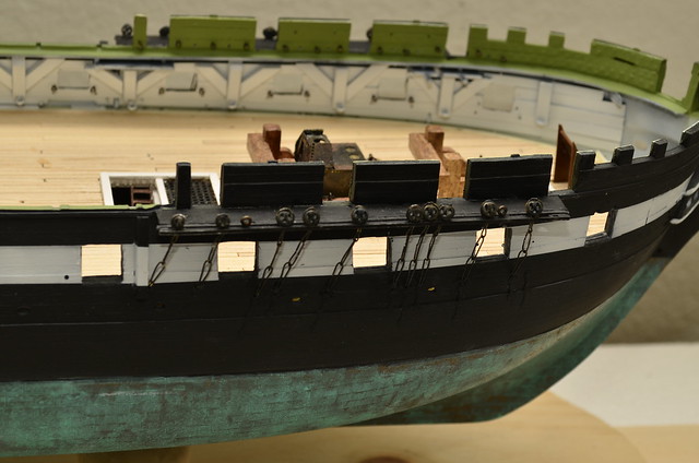
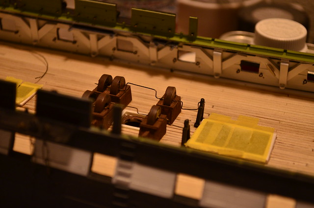
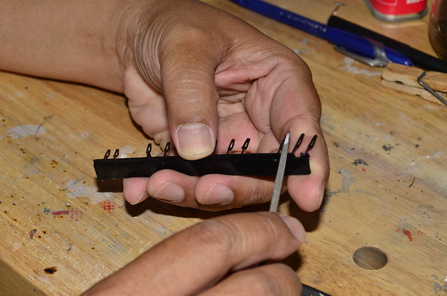
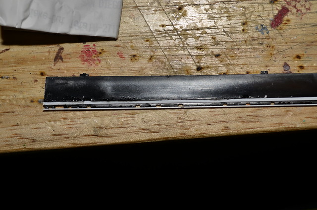
I took the existing chains underneath the Revell channels and using them as a guide, I carved in some rectangular notches with a needle file, where the deadeye strops would eventually go, then snipped off the chains and filed the nubs down.

_DSC8075 by Jose Gonzales, on Flickr

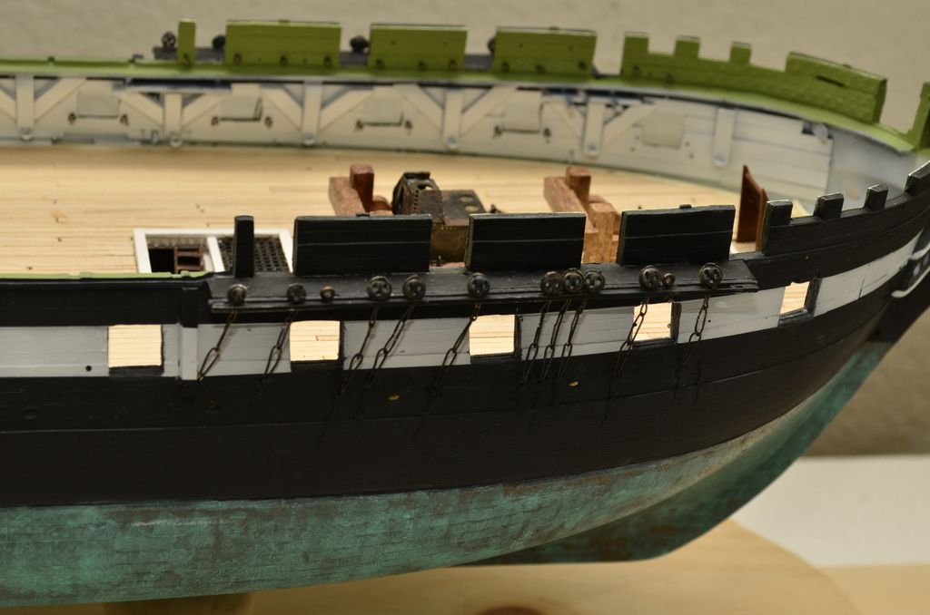
Originally, I tried CA gluing the strops into the notches, planning later to glue a styrene strip on the outside edge of the channel to lock the strops in, but the CA did not hold the strops in well at all, and any pressure I placed on the strops disconnected them (the tube of CA possibly was old, and may have lost its holding power). I switched tactics, gluing the styrene strip on the edge before adding the stropped deadeyes. I also added a strip to fill in the recessed area where the Revell deadeye assembly would normally have been glued atop the channel.

_DSC8078 by Jose Gonzales, on Flickr

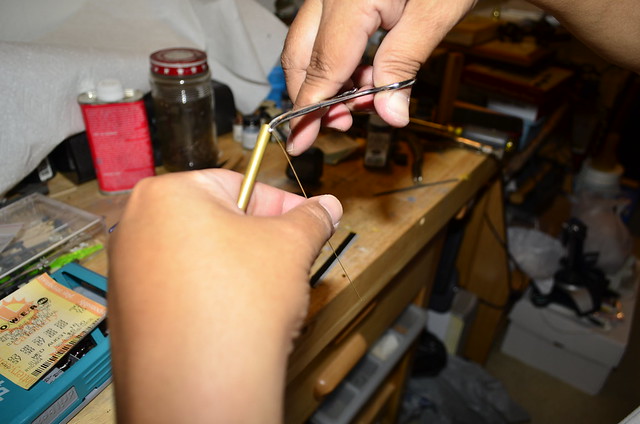
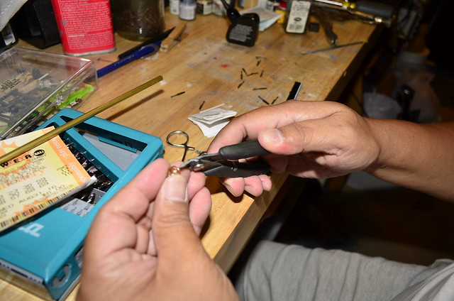
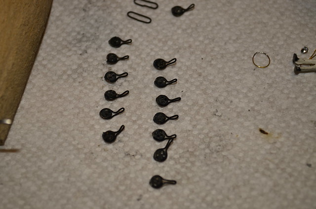
I then inserted the stropped deadeyes, added the chain link to the stem/loop below, and soldered the link shut. A couple of eyebolts were added for the Bentink shrouds and topsail halyards. All this was done before the channel was attached to the hull.

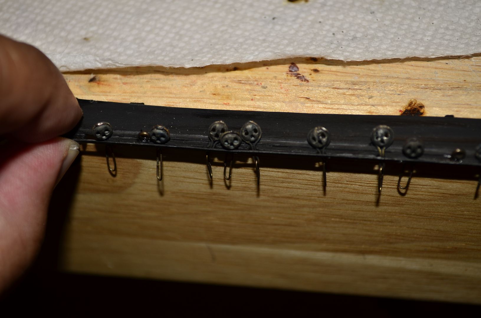
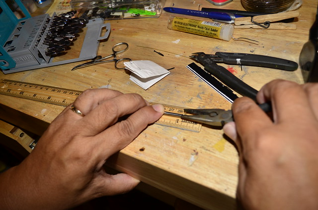
Note that for the fore and main masts, the deadeyes for the shrouds are 5/32 inch dia, while the deadeyes for the backstays are 1/8 inch dia.

The chainplates (flat iron pieces tacked through the last chain onto the hull to support the deadeye/chain assemblies) are molded onto the Revell plastic hull. The Bluejacket kit comes with chainplates, so I could have filed down the molded chainplates, but I chose to keep them. I drilled a hole into the hull just above each chainplate, then I took short pieces of wire, bent them, looped them through the chain loop attached to the stopped deadeyes and inserted the ends into the hole, to complete the stropped deadeye/chain/chainplate assemblies.

3 weeks have passed quickly since my last post. I worked almost every night, between 15 minutes and 2 hours a night, and seem to have relatively little to show for it so far.

Lower deadeyes are finally all mounted. They took much longer than I wanted to, for the previously mentioned reasons. The mizzen deadeyes were a size smaller than the fore and mainmast deadeyes, so their strops tended to snap even more easily, as I was trying to wrap the strops around a much smaller circumference.

_DSC8142 by Jose Gonzales, on Flickr

I added crank handles to the chain pumps. I may re-do them but I am not sure if the effort is worth it, since these will be barely visible through the main hatch and perhaps the gunports.

I added a few strips of wood to the captain’s cabin, specifically the window sill bench across the rear part of the cabin, and some square dowels to represent the stern timbers. They are slightly visible through the stern windows.

_DSC8146 by Jose Gonzales, on Flickr

I started mounting the ship’s guns. After rigging the breeching ropes, I realized that the guns were not secured to the deck in any way, so I drilled some very small holes into the deck and inserted short brass rods through an eyebolt on each side of the carriage, and secured the ends of the rods to the holes in the deck with CA. This will be okay for the guns that are hardly visible, but not how I want to secure the guns that will be near the main hatch. For those more visible guns, I will probably drill holes through the carriages themselves, perhaps through the quoins, to hide the brass rod pinning the guns to the deck. My last Constitution build did not have the guns secured to the deck with anything other than plastic cement, and a handful of them broke loose. Fortunately, I had wrapped the breeching ropes around the cascabels of the barrels and cemented them, so they stayed in place to some extent. I learned my lesson then - I must secure the guns to the deck with more than glue; some sort of pin or brass rod to pin them down to the deck.

Good going, Jose. The combination of kit parts, Bluejacket’s excellent fittings, and scratch-built enhancements has produced a most attractive model. I’m looking forward to seeing more as you progress.

Very nice. it’s all coming together. You can set up your cables and messengers. Maybe a pigsty up front too.

Jose,

I do not understand how I have missed this thread! I am deeply impressed by your work, although I am confused by your use of the word “wimpy” when comparing the Revell version of the 24 pounderers with the shorter ones from Bluejacket. They looked fine in your comparison photos; I would probably have gone with them for the greater accuracy.

I am also being somewhat reeducated about the Revell kit. I had once read that she resembled the ship after her 1924 refit and not in her 1812 configuration, and I have labored under that thought for decades. I am learning from you, Force9, and John Tilley that the opposite might be more true. I might have to tackle this kit once more (the last was when I was 13 in 1967.

I do have several of these kits in my collection, also collecting them from garage sales and such, including that “Museum Classics” version. It’s interesting to contrast the old pre-painted copper from the 1960s version against the “Museum” version. Revell had used a very bright copper for the older kits, and a “weathered” version with the latter. And, I agree about those so-called “cloth-like” sails. They are junk.

I have to agree with John about the vacuformed sails. I never thought that they looked right on a completed model. I also try to make my own furled sails, although there is a source for pre-made cloth sails, flags, and pennants that are quite nice. This source is HisModel out of Czechoslovakia. They do have a set for the Revell kit.

Again, great job so far!

Bill Morrison

Probably 7 per 24pdr; 7 on the 18pdr chase gun; 5 per truck croonade; and 3 per pivot carronade. With typically, only one side manned. There will be something between 20 and 30 to man the sails, who will aslo be on standby to repel boarders. There will be powder monkey, 1 per 4 guns (I think), then a party of mates & stewards and the like to bring shot to the racks. The Captain would be on the quarterdeck, with the Sailing Master/Quartermaster; the XO will be right forfard, the three Lieutenants each at a group of guns, with the Ensigns distributed about (and one each at the mast tops).

If it’s only a drill, the officers (and petty officers/masters) would likely be prowling the ship’s centerline watching the crew at their stations. They’d be in working uniform, too. Further, there’d be lookouts at the topgallants, too.

If a formal combat situation, the officers would have put on “proper” uniforms with lace, braid, and buttons.

Hello all,

I haven’t worked much on my model for a month, since my youngest son, who is a junior in high school, is in the marching band, and there have been lots of performances on the weeken and practices on the weekdays. The marching band season just ended, so I am ready to start up again.

Installing guns is slow work. After painting the carriages and wheels, and blackening the britannia metal cannon barrels, and drilling 7 holes into the carriage and mounting eybolts, ringbolts and rings, I had to mount the carriage to the deck, secure the carriage by drilling a hole through the quoin on the carriage down partway through the gun deck, threading a brass rod through the two holes and seciring with CA. I then mounted the barrel and rigged the breech rope. I am up to 11 guns mounted out of 30 on the gun deck, and I still have to decide how many of the guns I’m going to mount the gun tackles on. _DSC8140 by Jose Gonzales, on Flickr

Note that I’ve covered up the opened main hatch to prevent things from falling through to my pseudo-berth deck.

On the stern, I mounted several eyebolts under the windows, and a pair on the rudder, in preparation for the rudder retention chains/cables. I’m trying to decide how to depict these, as I’ve seen several different representations on several differnt resources. I also added port covers for the cargo loading ports on the berth deck at the stern. I did not actually drill ports through the hull. I simply took some unused plastic gunport covers from the Revell kit and sanded them until ultra thin, then simply cemented them in place on the stern._DSC8638 by Jose Gonzales, on Flickr

One more shot of the current state of the model. Note the red window muntins across the stern and quarter galleries, a la Miguel Felice Corne’s paintings, with a white gun stripe, ala the Isaac Hull Model at the Peabody Essex museum._DSC8640 by Jose Gonzales, on Flickr

Hello all,

I decided to rebuild this build log with my photos formerly drawn from photobucket re-drawn from Flickr. Currently I have mounted all 30 guns on the gun deck, and am halfwayh through rigging the tackles. I’ll post pix soon.

Jose

Hello all,

2 months since my promise to post more pictures; work and family life have kept me busy. Here is the current state of the model._DSD1929 by Jose Gonzales, on Flickr

30 guns have been mounted, and tackles rigged one one each side. I’m working on adding coils to each side.

_DSD1928 by Jose Gonzales, on Flickr

Ringbolts have been added to the gun deck for rigging tackles for retracting the guns.

_DSD1927 by Jose Gonzales, on Flickr

Stanchions were added from the BlueJacket kit. They had to be shortened because they were too ttall for the space between the Revell spar deck and gun deck, especially since I added deck planking to the gun deck, raising the height of the deck by 1/32 inch. I will also be lowering the spar deck as described by the late Professor Tilley in the following post in order to give room to plank the spar deck:

I will be following a lot of his suggestions, and will include links to the relevant forum threads when I can find them.

[

I am also facing a couple of decisions before starting on the spar deck. One, should I add a detailed captain’s cabin replete with furniture and sleeping quarters, or leave the gun deck cleared for action? two, how much detail should I add to the manger area, since it will be nearlh invisible anyway.

I plan to add anchor cables, wrap them around the anchor bitts and drop them down the main hatch. The drops will be visible down past the pseudo berth deck, to the invisible cable tiers in the orlop area. I don’t plan to add the messenger cable round the capstan, but I may change my mind on that - stay tuned!

Cheers!

Jose

](https://forum.finescale.com/t/wood-decks-on-the-revell-1-96-constitution/142905/20)

Jose,

Merry Christmas! It’s great to see you back! Great work so far.

Bill

Thanks Bill, and Merry Christmas to you and yours!

very nice jose , keep it coming . hope you had a great x-mas

steve5

Jose, tks for re-posting the pics. I am currently building one too. I have detailed the gun deck cannons a bit, but not to the levels you are. I am planning on doing more on the main deck guns. Your right about the hours involved in just getting all those little cannons done. I used the cannons from the kit and there is lots of trimming to be done. I am in process of putting the gun deck in now. Happy Holidays Dale

Happy Holidays all. Great work Jose.

i would certainly think about a messenger for the cable.

Hello all,

Mr Morrison, after thinking about it, I am inclined to agree with you. Although the gun deck capstan will be nearly invisible, the anchor cables, if I choose to incorporate them, would be clearly visible through the main hatch, and while I might be satisfied to show them as wrapped around the bits and dropping through the main hatch down to the orlop, the addition of the messenger cable would be a very nice addition to the detail, so I will show one cable wrapped around the bitts, and also secured to the eyebolts by short ropes, and the other cable tied to the messenger. I’ve added a couple of crossbeams aft of the pumps to keep the messenger off the pumps:

_DSD2099 by Jose Gonzales, on Flickr

The crossbeams are supported by brass rod through the middle and down through the deck.

If memory serves, Constitution’s anchor cables are either 39" or 37" circumference–around 12" in diameter. They are typically a cable’s length–1000 yards, or 500 fathoms long.

Now, with manila line, you do not bend it to a radius smaller than 3 times diameter.

So, really, you’d never actually see an anchor line actually wrapped around bitts–far far easier to use 3" (1" dia) line as a stopper hitched around the anchor cable, and taken firmly around the bitts (and will far better grip the radii of those bitts).

Even when chain rodes were introduced, they were stoppered with line to bitts. The chani stopper with a pelican hook does not make an appearance until about 1890 with the steel Navy.

So, yeah, the anchor cable wants being about 1/8" (3+mm) diamter to be in scale. The messenger is typically 5/8 the size of the rode, that would be about 5/64" (2mm).

Sources are a tad contradictory on whether the messenger was nipped (tied off with 1" (3/8 dia) lines about 4’ long) to the rode or not. Would make for neater seamanship in not having the messenger slither about the deck in an untidy way. The messenger will have three or four turns around the capstan. Thos turns might be slacked off and nipped clear of the capstan if the spar deck portion were wanted for hoisting away jeers or the like.

The English expression “whippersnapper” to mean a preoccious youngster comes from the messenger and the capstan. The ship’s boys would tie off the nips binding the messenger to the rode about every four feet or so. As the messenger reaches the capstan and the gruf sailors heaving at the bars, the boys (nippers) would cast off the nips. If they got a kick from a tar, they might snap the nip against the bare feet and legs of the tars; they would snap the whips.