1/72 C-130E(I) Rivet Clamp Special Operations Aircraft - Operation "Stray Goose"

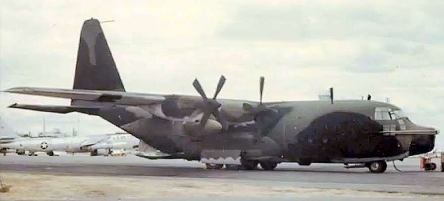
In 1971, while stationed at Nha Trang AB, Vietnam, I was fortunate to work on four C-130E(I) Rivet Clamp aircraft assigned to the 90th SOS that conducted special operations under the code name “Stray Goose”. These were specially modified C-130E aircraft that were painted in a black and green camouflage scheme, which gave them a very sinister look. The Rivet Clamp aircraft were later upgraded and re-designated as MC-130 Combat Talons.

The many unique modifications of the Rivet Clamp aircraft included Terrain-Following Radar (TFR), Electronic Countermeasures (ECM) sensors, Forward Looking Infrared Radar (FLIR), Low Light Level TV (LLLTV), and the “Black Crow” Radio frequency Intelligence (RINT) sensor for locating ground vehicles. Many of the sensors they carried would later be used on the AC-130 gunships to locate targets; however, the Rivet Clamp aircraft carried no weapons. The Clamps also carried a host of special navigational gear and radios. And they were equipped with the Fulton aerial pickup system, made famous in the movie “The Green Berets”.

I was an ECM technician assigned to First Flight Detachment which was, at that time, part of the 90th SOS. Our primary job was supporting the C-123K “Black Bat” aircraft, but we also supported two defensive systems on the Rivet Clamp aircraft.

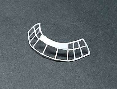
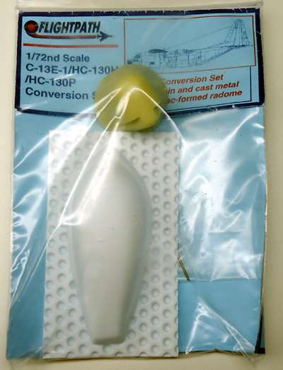
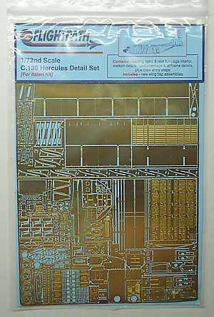
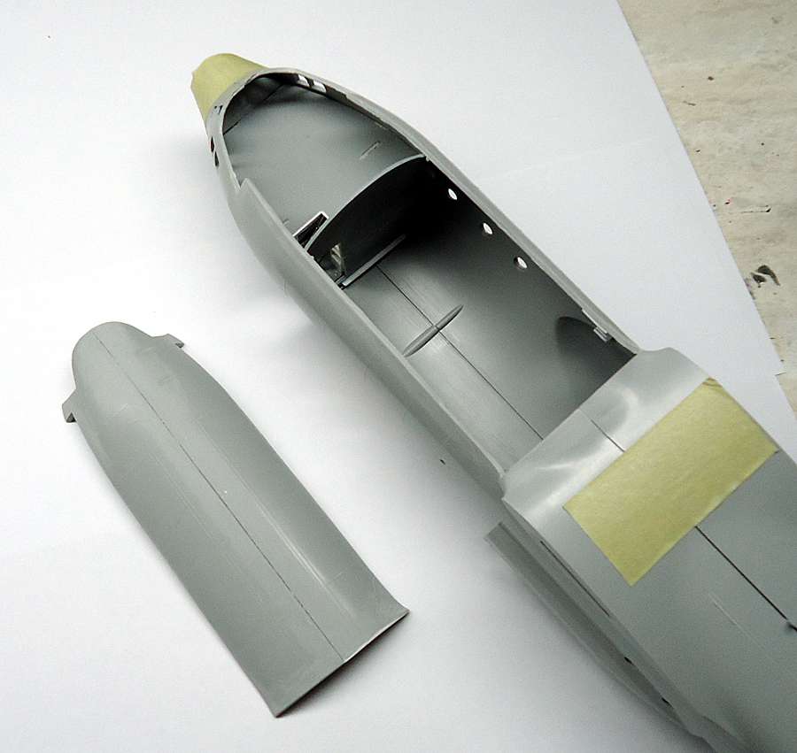
The aircraft I’ve decided to model is aircraft 64-0555, “Triple Nickel” (shown above) using Italeri’s 1/72 C-130E/H kit No. 015. I’ll be modifying the nose with a Flightpath C-130E-1/HC-130H/HC130P Conversion Set and adding some PE detail from Flightpath’s C-130 Hercules Detail Set. Everything else will be scratch built.

That’s a nice kit and I like your AM parts! Wow, lots of PE. I’ll be following.

Toshi

P.S. Yes, I too became a victim of PB. I now use Flickr. I lost all my photos on this forum. 2 years of builds!

Striker,

Fantastic project. With your knowledge and personal experience with this beautiful aircraft this should be one for the books. I hope you enjoy every second of this build. I will definitely be here watching.

The front part of the Rivet Clamp cargo deck was blocked off from view and held consoles for the 2nd navigator, ground sensors operator, ECM equipment operator and radio equipment operator. In order to be able to see the detail in the crew cabin and cargo hold, I cut out a section of the top of the aircraft that will be removable, as shown below.


The Italeri’s flight deck was incorrect, as was the rear cabin bulkhead so I made my own versions of both, as shown below.

I also started detailing the lower deck equipment bay, the galley and the navigator’s position. I modified the kit supplied navigator’s seat and added seat belts. I also added the circuit breaker panels along the sides of the flight deck.


The picture below shows the raised deck for the pilot,co-pilot and engineer’s seats temporarily in place. I also went ahead and scratch built and detailed the center console. It was necessary to get the raised deck and console in place to accurately position the main instrument panel.

Here is the finished flight deck with the center console in place and seats painted. The scratch built rudder pedals are a bit large but they won’t be seen very well anyway, so I didn’t change them.

I didn’t care for the kit instrument panel so I made my own, as shown below. The instruments are a photo compiled from several pictures, printed on photo paper and cut out and glued to the new panel. At this scale, the lack of depth of the instruments is not noticible.

Here’s the completed flight deck, followed by a picture showing it installed in the aircraft.


I added the left and riight side control panels for the pilot and copilot. The PE nose gear steering wheel was way too small so I made one from sheet plastic.

Below is a picture of the finished cockpit area with the fuselage halves temporarily held together. Now I could go on to the cargo deck detail.

Thanks Chris and Toshi! Glad to have you both aboard!

Cheers,

Russ

Tracked you down Russ ! :slight_smile:

Looking forward to seeing this thing come out the spray barn !

Cheers,

Haydn.

Hay, Haydn! [:)] Ya, me too, bud. I’ve started with the bottom but RLI keep getting in the way. Hope to get most of it done this week.

Cheers,

Russ

All signed up and following along Russ. Looking forward to the updates.

Steve

Well, before I added the consoles, I wanted to add detail to the back of the crew compartment bulkhead and along both sides of the forward cargo area. The first picture below shows the right side details, the second the left side.

The upper rack on the left side is the LS (life support) rack. The crew parachutes are hanging below. The ladders were used for emergencies.

The next photo shows some of the detail added to the removable roof section. Those long green things are air ducts.

Below is the finished removable section. The tan area in the photo is the ceiling over the crew compartment and includes the overhead control panel cluster. The actual overhead panels were much more extensive than what I added, but I could never find a good enough picture of them to render them properly.

Next are some photos of the evolution of the Talon compartment detail, starting with the main console. The actual main console was slightly different but I couldn’t find any photos of it so I used pictures from the Talon I.

The next pictures show the main equipment rack. Again, I had to go by the Talon I configuration but they were probably pretty much the same since space on the aircraft was extremely limited.

Here’s the completed compartmnent.

And here’s a shot of the partition at the back of the compartment. A black curtain covered the entryway when passengers and non-cleared personnel were present. The Talon compartment was classified Top Secret.

Hello Russ!

This one is just fantastic! I always wanted to build one of those, but the references are just non-existent - those birds were so top-secret, and after that they modified them over and over and over and nowadays even if you found one such aircraft it looks completely different. So your “been there, done that” might be the only source of knowledge available! On top of that your detailing is top notch! Those instrument panels, those ducts look very good! So good luck with your build and thanks a lot for sharing, have a nice day

Paweł

Hi, Pawel!

Thanks for the good words!

Cheers,

Russ

This kit is pretty good overall, but there were some areas that needed upgrading. I started with the main landing gear. The gear wells were bare and the main strut assemblies were mostly inacurate. I threw away the kit gear wells and made my own and then I modified the strut assemblies, as shown below.

The nose wheel well was pretty sterile and even though most detail will be hard to see, I added one feature that the kit left out - a bulkhead at the back of the wheel well, as shown in the photo below. I built the bulkhead out of sheet styrene and strips and added HO scale rivet decals. I also added some piping.

I made a few changes to the nose gear as well.

One important feature needed to be added…the ECM chaff ports on either side, just ahead of the troop doors. The picture below shows the chaff ports on the right side. They’re located just above the guy that’s sitting on the fire extinguisher. The same setup was repeated on the left sponson.

Below is my rendering of the chaff ports. The second window (above the chaff ports) was done away with on both sides because of the chaff dispenser equipment inside.

Below is a model of a single chaff dispenser unit that held two chaff magazines. There were 8 of these dispensers - 4 on either side, for a total of 16 magazines (same setup as in the B-52D).

The next picture shows the right side dispensers and magazines mounted in their cabinet (with the doors removed) and the following picture shows the left side dispensers represented with just a cabinet.

Since I had already detailed the cargo area back to the troop doors, I decided (reluctantly) to go ahead and detail the ramp area. That was a sore trial indeed since, unfortunately, none of the PE parts were suitable and I ended up scratch building all the detail.

BTW, our receivers were mounted on racks on either side near the roots of the horizontal stabilizers but they wouldn’t be visible with the ramp doors open so I didn’t add them.

Below are both halves with the interior detail completed.

Now it was time to close up the fuselage, also a sore trial.

Once the fuselage was closed up, I addressed the cockpit windows. I didn’t like the way the thick clear plastic canopy looked so I decided to make my own. I used the canopy as a template and built the window frame out of thin styrene strips, intending to use glazing for the windows. After the new nose was on, I sanded down the window frame until it was flush with the body.

The nose radome, as it came in the FlightPath AM kit was not correct for a Rivet Clamp aircraft. The radome was too long, and it was not shaped correctly. I had to cut off about 5 mm and do a lot of sanding and filling to get it to the right shape. Below is what it looked like before and after modifying it.

Interesting build, very convincing.

Hmmm;

Being as how the C-130 in any model is my really favorite non Sea-Plane prop driven bird , I certainly like what you’ve done here .Very nice .

First, thank you for your sevice. Second, wow what a ton of dimension and depth to that interior. Really enjoyed everything you posted so far here.

Wow, you’re doing a fantastic job on this kit! Your IP scratch building is superb as well as every single attention to detail you’ve put into this. What great project!

Toshi

Russ, wow, thats another really amazing build andyour attention to detail is first rate.

What do you make of the Flightpath conversion. I’m looking at getting an Italeri Herc and useing the flightpath conversion to do a stretched RAF version.