1/72 B-52D with Big Belly Mod, Operation Arc Light

I came across some aerial refueling pictures that show I had the EWO hatch represented incorrectly as a scribed outline. In actuality, the EWO hatch had the same cover as the other hatches (see the first 2 pictures below). I filled in the scribing and modelled the hatch and I will also add the guide marks above the cockpit ahead of the refueling probe, as shown in the third photo.

Cheers,

Russ

EWO hatch update - I discovered the EWO’s hatch is actually the same type as the Bomb-Nav hatches; it was just really hard to see in the photos. The picture above shows the rounded support plate extending the full length of the hatch but it actually goes only half way. I will have to wait to correct this until I close the fuselage.

NOTE: Information in brackets [ ] has been copied from a previous thread into this post without responses and comments, so some disconnects in the dialog may be apparent.

**[**Here is my APS-104 nav radar antenna that will go into the chin. Since the plane will be part of a diorama, the chin radome will be shown removed while the radar is being worked on. Unfortunately, I only found one picture of the antenna and that from the back. I had to guess at the feedhorn assembly.

]

I’m just about to button up. I finished up the nav antenna compartment (chin radome), such as it is, with a sprinkling of equipment to simulate much more that would be in there; unfortunately, I don’t have any good pictures of this compartment, probably because the equipment in those days was classified or sensitive. I’ll wait to install the antenna until I put on the final fuselage details.

I added the upper port and starboard cooling vents in the 47 Section but will have to wait on adding the lower 6 until after the fuselage is closed and I start on the ECM antennas.

**[**Below is a picture of the turret on a real aircraft and my model of the B-52D gun turret with the right-side cover removed for maintenance. I remember watching the MMS troops working on these guns. They would be up to their elbows in oil and grease in the blazing hot sun. Those guys had the hardest job of all, even worse than ECM, and we worked really hard. A lot of MMS troops eventually deleloped liver or kidny problems or cancer from working with the gun grease remover. No other shop had more to do or worked harder than MMS.

]

**[**Below is a picture of an actual B52D tail gunner’s compartment (courtesy of G. Holmes) and my model with a few details added - my details are only suggestive, not accurate.

I’ve had to work in this compartment many times. It’s very narrow and confined, with cables, hoses and cords hanging down that make it even more crowded. The seat folds down so you can get in and out. There’s a hatch that opens to the outside at the right rear of the compartment and another hatch just past that one that opens inside into the 47-section where we had our jamming transmitters and chaff dispensers.

]

56-612 is finally buttoned up! I will be adding the cockpit and tail gunner canopies next once I get them painted. I’ve also started re-scribing the vertical stabilizer. A lot of errors there in the panel lines - I don’t intend to be fanatical about them but I do want the majority of the lines to be reasonably accurate. The kit also left off what is most likely an antenna cover near the top that I’m adding on either side.

Cheers,

Russ

I apologize if this has been asked and answered already. I read through all the posts and didn’t see this but who’s kit are you building? Things are looking great!

No apologies necessary, my friend. In fact, my thanks to you for pointing this out. I didn’t realize I left off the model description in the introduction. I will correct it.

The model is Monogram’s 1/72 B-52D, kit #5709.

Thanks for stopping by, and for the good words [:D]

Russ

She’s coming along great Russ, please keep up the good work!

Thanks, Gam!

For a change of pace, I’ve started on the wings. The trailing edges of the real wings on the B-52 are very thin compared to the overall wing dimensions and the kit’s edges are pretty thick, so it requires a lot of sanding to get them even close. One note: if you’ve ever been around a fully-loaded and fueled buff with the flaps fully extended, the corners of the flaps are about at eye level and very sharp and pointed. Definitely a safety hazard but oddly enough, I never saw any safety cushions for them. You just had to be careful walking around them.

Since I plan to have bomb loading in progress, the flaps have to be in full up position for ground equipment clearance. That requires a lot of work to get the trailing edges of the flaps to match up with the wings - the kit flaps were obviously not intended to be fully retracted in the model. Sadly, the model’s flap assemblies don’t look anything like the real flaps. I had to fill notches in the back edges that do not exist on the real flaps. The picture below shows progress on the wings.

Updated 7/9/19

Also, I wanted to show the ailerons “cocked” as they often were. To do that, I had to cut them out - a very frustrating task since the top edges don’t exactly match up with the bottom edges.

I discovered that it would be best to cut the ailerons out from the bottom of the wing, as shown in the photo below, using the sides of the bottom part of the aileron as guides. The cut-out ailerons should look like mine in the picture above, only a lot cleaner.

To show the ailerons cocked on the model, glue one pointing up and one pointing down. The photo below shows the left wing with the mounted aileron in the down position; if flying, this would indicate the plane was making a right turn. Now, if you’re really picky, you’ll want to have the controls in the cockpit turned to the corresponding position - to the right in this case [:)].

Cheers,

Russ

Hello, All,

I’ve finally completed the bomb lift trailer (again). I had to rebuild the end unit to make it larger so it could accomodate the trailer. Unfortunately, I lost the numbers in the process, but hope to find some more soon. The images below show a bomb clip transporter before and after it’s moved into the lift trailer.

Cheers,

Russ

[ NOTE: The wheels on the transporter here are too small and were later replaced with correct size wheels. Also, the transporter itself was upgraded, as shown below.]

Upgraded Transporter

Nice work Russ! Your attention to detail is amazing! [Y] [Y]

Ken

Thanks, Ken! [:D] There’s a color mismatch between the two - I want the colors more like the lift trailer so I’ll touch up the bomb trailer later. Hopefully I can also find slightly larger wheels so I can make the trailer look more like the real ones.

Thanks again, bud, for the good words!

Russ

Striker8241

Bockscar

Russ:

What did you use to saw that flap out?..and what did you fill it with? -Thanks

Dom

Hi, Dom,

I assume you mean the aileron since I didn’t do any cutting on the flaps. I used a sharp #11 blade and a flexible straight edge and just kept cutting until I was through. Check the alignment of the edges of the aileron top and bottom with the flap openings - mine was off a bit on the bottom of the left wing and I had to cut at a slight angle. The pieces are so thick that I didn’t need to use any fill.

Russ

Thanks Russ:

After what you mentioned about flap assemblies not being very accurately detailed, I wasn’t sure what I was looking at there, I haven’t been around enough BUFFS to know. That sounds like a good cutting strategy, I’m guessing it kept the cut gap to a minimum tolerance.

Err, I do know what those spoilers look like though…that one would be hard for Monogram to mess up…Tx again

Flaps down, yeh, pretty close to the ground:

So Russ, is that gap in the flaps for the engine blast, is that where the aileron you’ve cut is positioned?

Dom

"God does not subtract from our time on earth

the hours we spend modeling."

Russ: Thought I should post those BUFF snaps here.

That lift assembly looks great![Y]

Dom

Hey Dom,

That bird is riding pretty high. Likely it’s not been refueled or bombed up. With a full fuel load + bombs, the wings will be much closer to the ground and the inner flap corners (on either sides of the ailerons) will be right about head level.

Yup… Remember though - the D-models were the last to use ailerons [Correction - the F models were actually the last with ailerons]. Your pictues are of G or H models.

The ailerons are pretty well outlined on the model, including the two trim tabs at the bottom. Just check that the aileron edges match up top and bottom.

And thanks for the good words on the lift trailer [:D].

Cheers,

Russ

Russ,

thanks for that reminder,

I’ll have to go back and find a D-model to have a closer look.

You brought up a good point, I remember hearing someone on a show on

the Military Channel say the BUFF had no ailerons, only spoilers.

I wish I could have heard the conversations a Boeing about

getting rid of that feature![:)]

In the meantime, here she is, flaps up:

Dom

Nice! [:D]

The ram air intake port at the left wing root is not rendered correctly, at least on my model. The model has it extending into the upper wing, similiar to the input port near the pylon. However, the port should only be on the lower wing root, as shown below. To correct this, you’ll need to fill in the upper section.

I discovered that the easiest way to cut out the ailerons and keep them straight on the B-52 model is to cut from the bottom of the wing following the edges of the flaps. The aileron outline on the bottom seems to be more correct that those on top. There may be some ragged edges on the top wing, flaps and top of the aileron, but you can fill and sand these.

Cheers,

Russ

Hi, All,

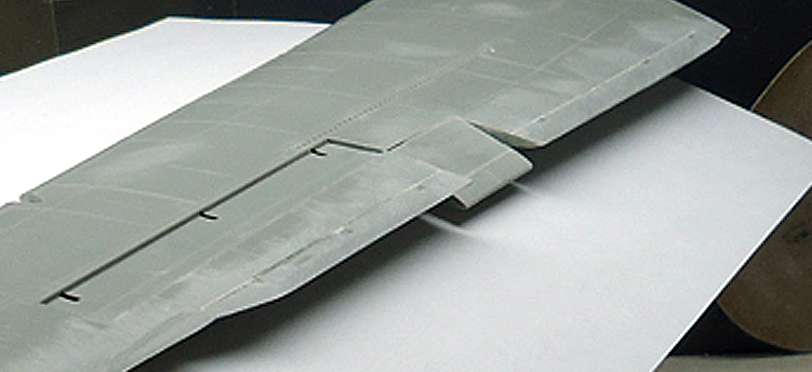
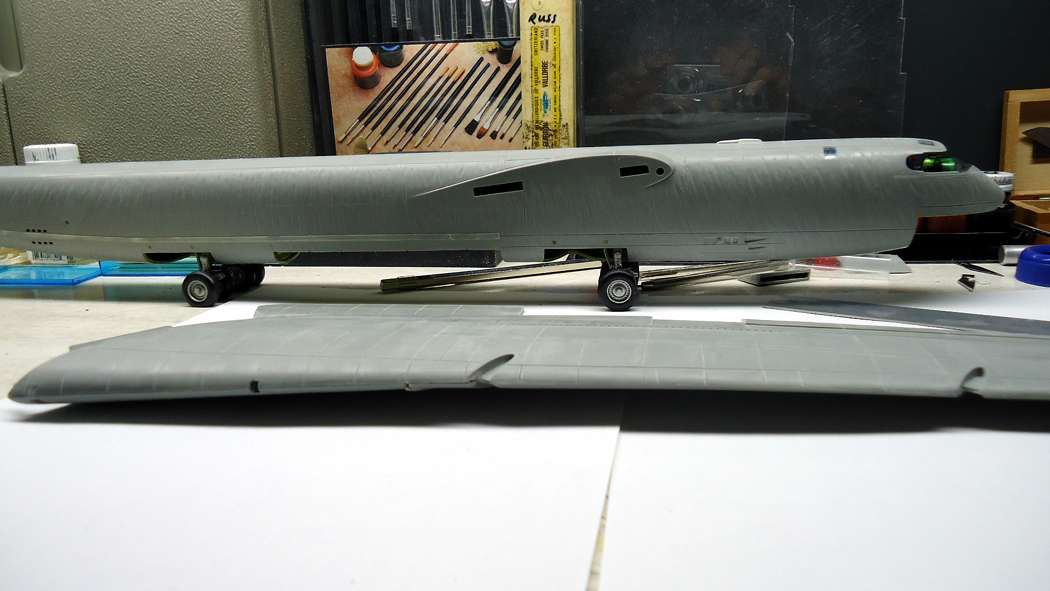
Sorry I haven’t posted any updates in a while. I’ve been struggling with these wings. And I thought the fuselage was difficult! At any rate, I finally got the wings scribed (I decided not to scribe the undersides since they won’t be seen anyway, so that saves a lot of work).

Updated 7/9/19.

When I tried the wings on the fuselage I discovered that they don’t have the necessary droop for the outrigger gear to touch properly. I read previously of one modeller’s solution to this, but he cut slots in the top wing to insert strips of styrene. I didn’t want to mess up the top so instead, I removed a 1 mm strip on the underside of the wing. If you want to try this, follow the steps below.

NOTE: You will need to have the fuselage assembled with the main wheels attached to test the wing droop.

1.) Assemble the top and bottom wing sections according to the kit instructions and glue them together. Do not glue the flaps in! Once the wing is dry, pull the flaps all the way out, or remove them.

2.) Lay each wing with the bottom side up.

3.) Measure 135mm from the wing root along the leading edge of the wing and make a mark.

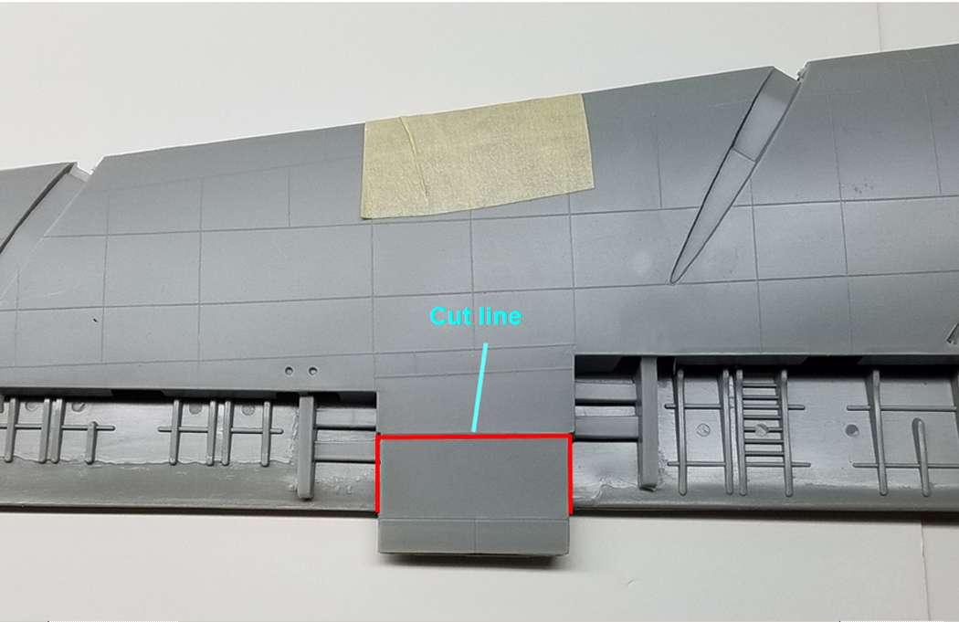
4.) Starting from the mark, draw a line parallel with the inboard slot for the nacelle strut, to the trailing edge of the wing.

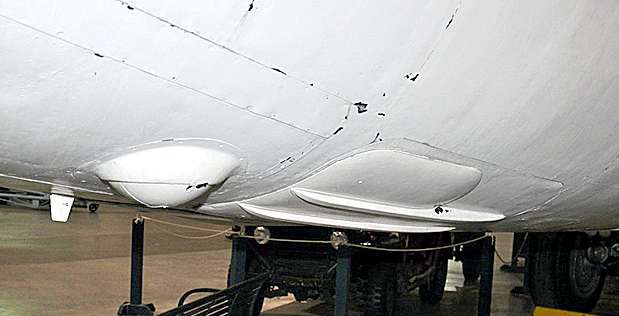
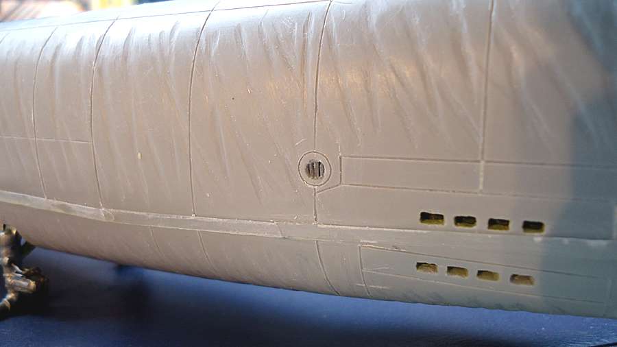
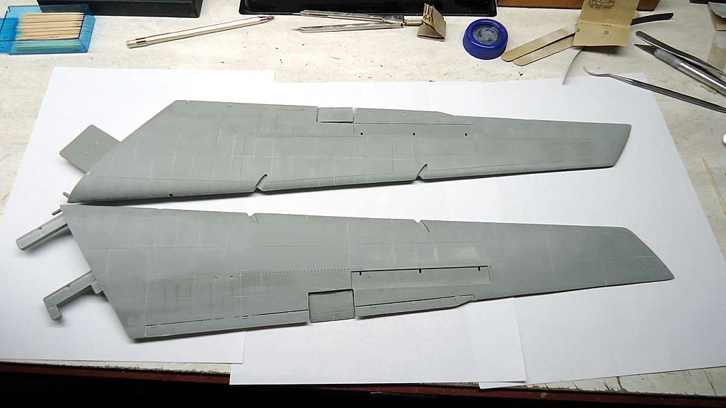
5.) Using a sharp #11 Xacto blade, carefully make a 1 mm wide cut along the line (see first photo below). Remove the cut material.

6.) Place objects under the wing on either side of the cut so that when a weight is placed over the cut, the walls of the cut will close together.

7.) Remove the weight and apply a strong glue to the cut, then reapply the central weight.

8.) Perform the same procedure on the second wing. Allow the wings to dry for at least 24 hours.

9.) Sand and finish the cut areas.

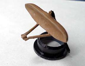
10.) To verify the wing droop, cut two wooden toothpicks to the length of the outriggers from the bottom of the tires to the tips of the mounting pins at the top of the gear.

11.) Insert the toothpicks into the mounting holes for the outrigger gear.

12.) Place the model on a flat surface and temporarily install the modified wings in the fuselage. NOTE: If you’ve already flattened your main gear tires, you will need to flatten the outrigger tires to match the length of the toothpicks. Keep in mind that the outriggers slant slightly backwards with the wing installed so flatten the tires accordingly.

13.) Verify that the wing roots are flat against the fuselage with the tips of the toothpicks resting on the surface. If the the toothpicks are too long, you can compensate by flattening the outrigger tires accordingly. If the toothpicks are too short, You can lengthen the pin at the top of the outrigger assembly.

14.) Carefully re-install the flaps. You may have to shorten the length of the flap assemblies slightly and institute a slight curve to match the wing’s new curve.

Cheers,

Russ

Russ, your a braver man than me re scriding those huge wings. This is looking good.