1/6th scale SDKFZ 222 armored car project

Hi guys, about a year ago I acquired this unassembled M&C flat armor SDKFZ 222 armored car kit from another customizer in a trade.

After I burned through some of my other projects I decided to grab this project and build it since it fits into the early war German armor series that I have fell into.

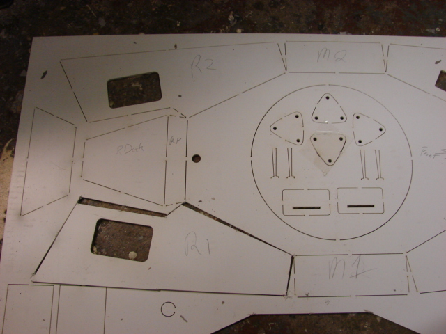
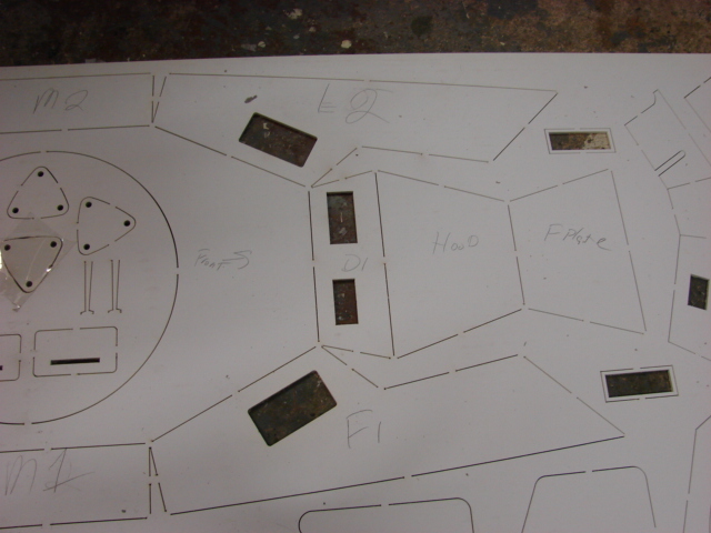
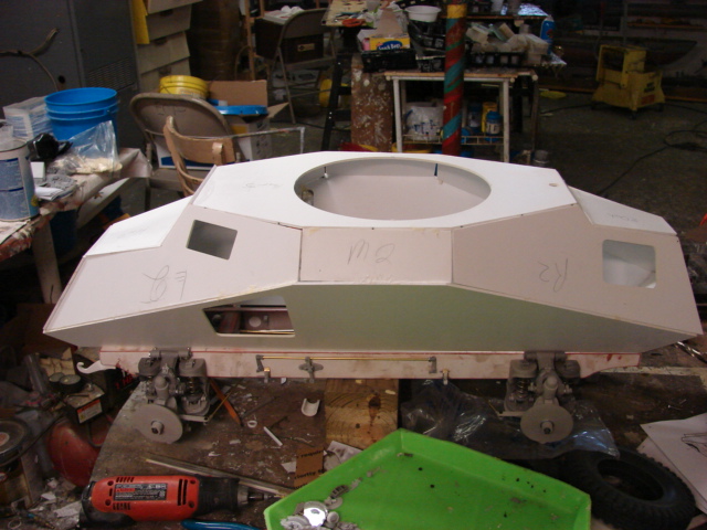
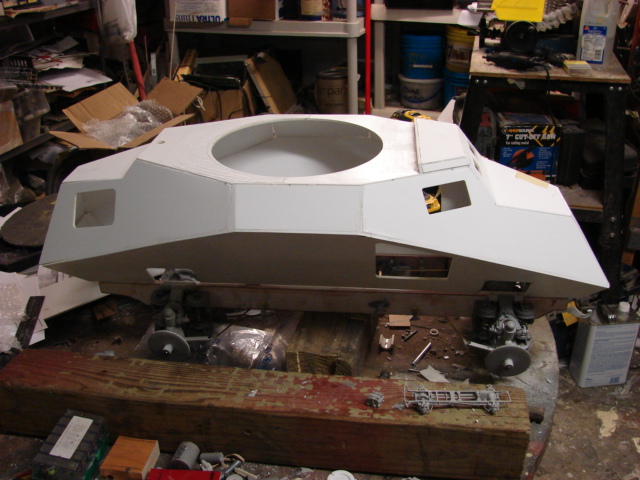
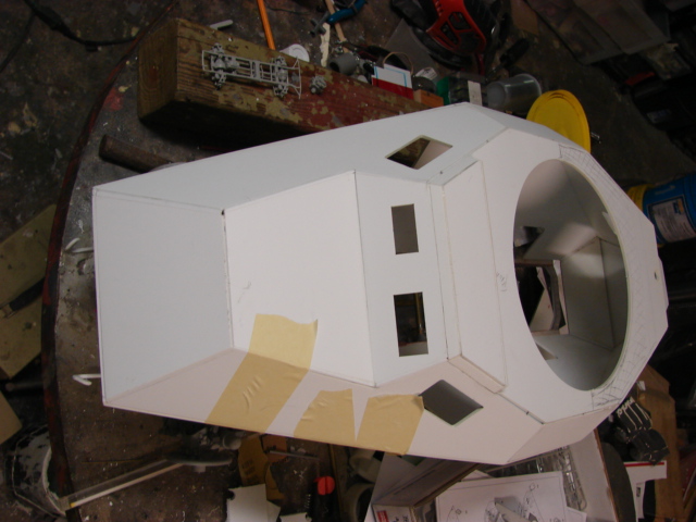
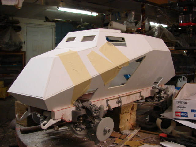
For those who are unaware of these kits, the kit itself is all comprised of laser cut 1/4 inch thick polystyrene plastic sheets. The kit is designed to build a very bare bones exterior model of the 222, and the kit doesn’t come with an interior, detailed undercarriage, and wheels.

An unboxing video was added to youtube which shows what the kit is comprised of. http://youtu.be/ewET0JIAh7c

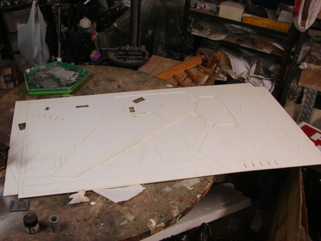
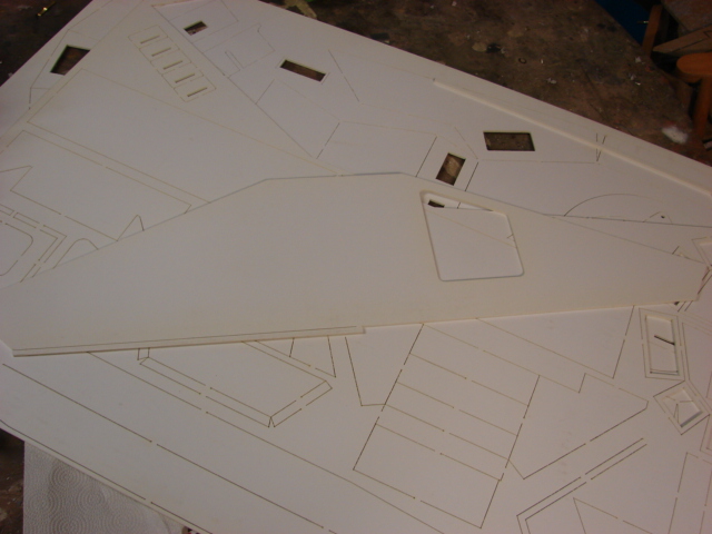
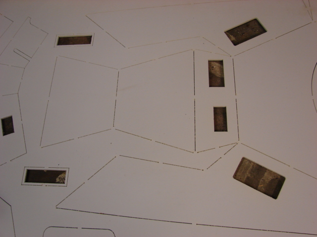
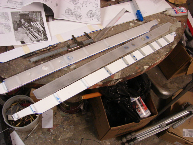
For this model I want to build the model with a detailed undercarriage and interior. To start I need to work on the chassis. For the frame the kit supplies you with a floor board, and two frame strips.

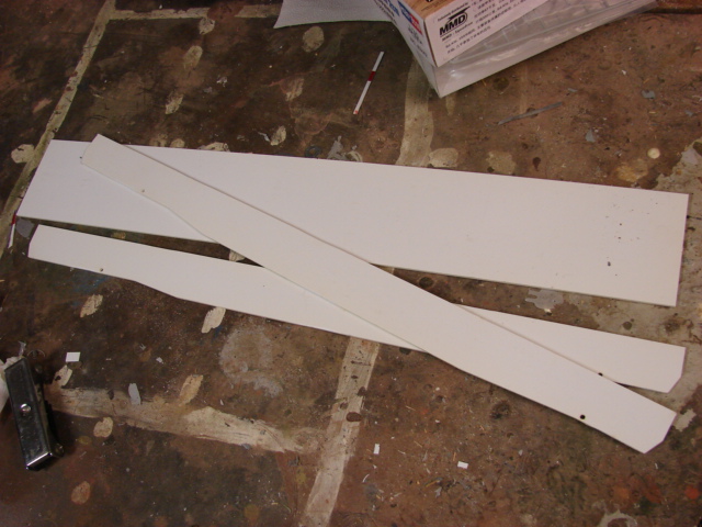
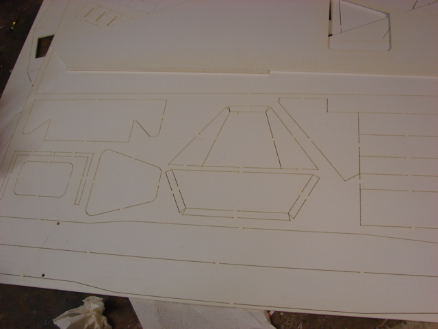
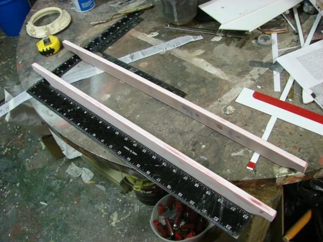
To fabricate the box frame I needed to first rework the frame panels. The panels themselves are too wide and have what appears to be the shape of frame sides from another German armored car.

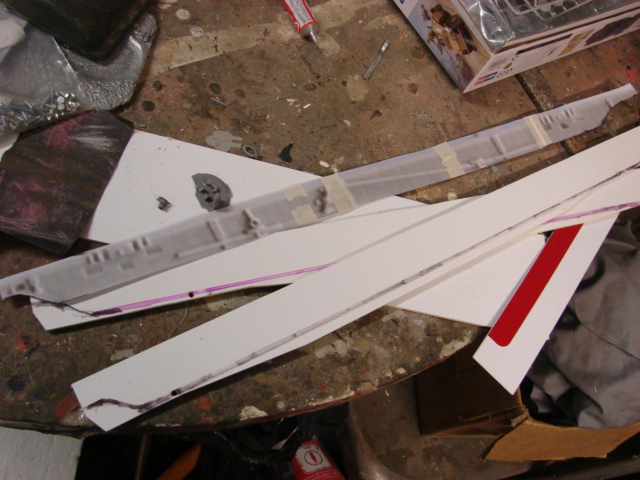
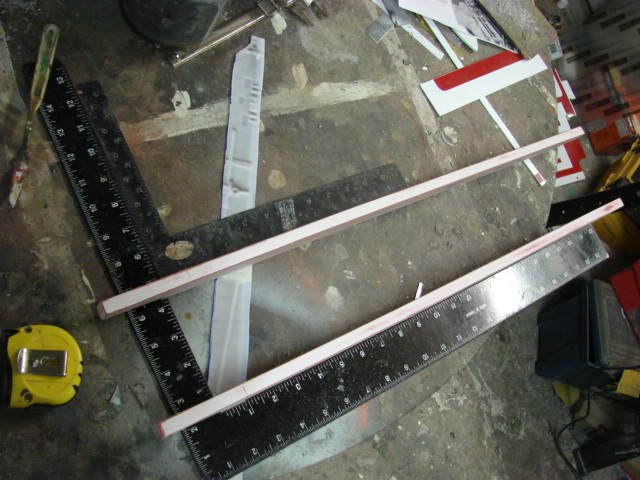
To rework the frames I scanned a 1/35th scale 222 model’s frame into my computer and scaled it up to the length of the kit panels. Then I printed them out and used this template to mark and cut the frames to the desired size.

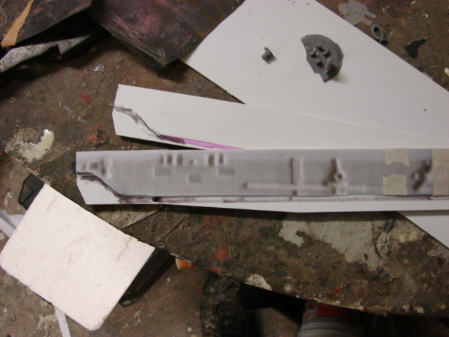
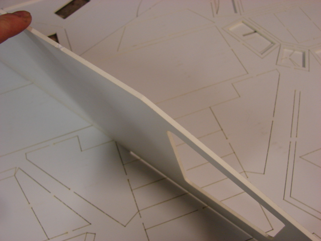
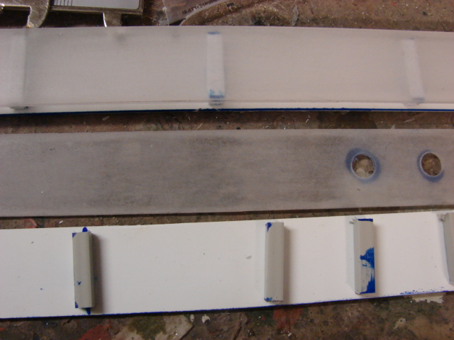
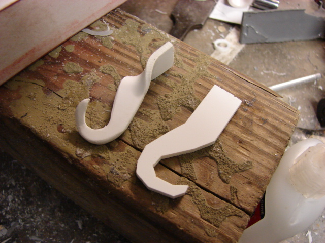
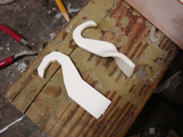
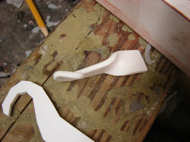
After the panels were ground and deburred I needed to make them into a tube structure. From one of my reference photos the 222’s chassis side frames were a tube like structure like an car. To get this effect I traced the frames onto 1/8th inch lexan plastic and for spacers I used segments of 1/4 inch square plastic tubing.

The square tubing gives a uniform thickness to the part which is crucial for the alignment.

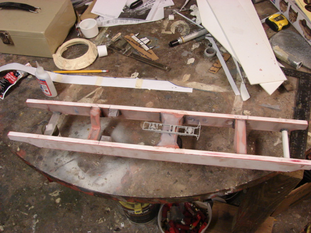
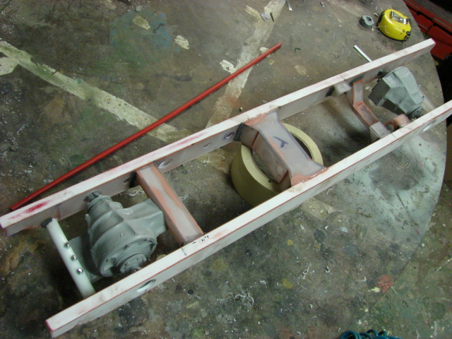
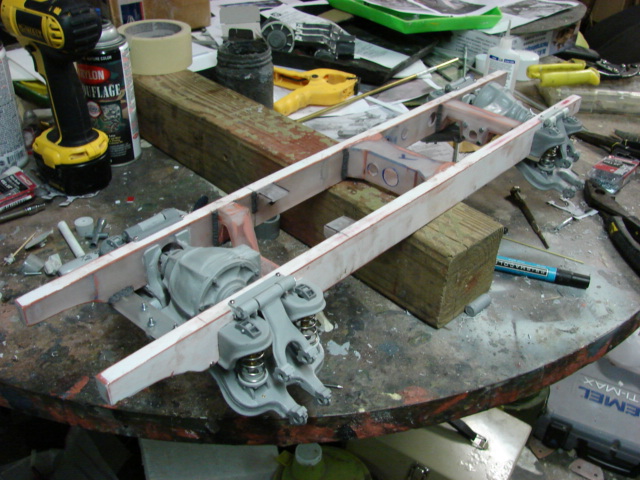
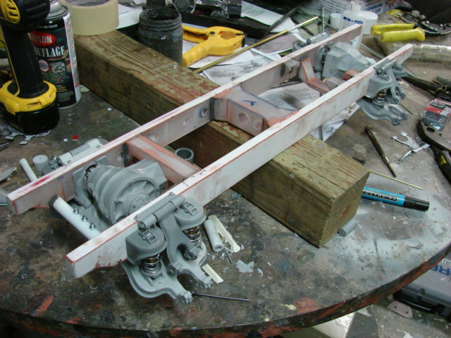
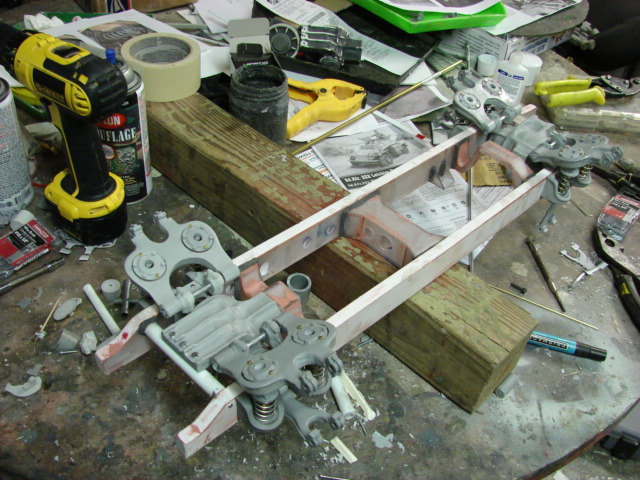
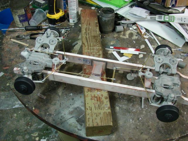
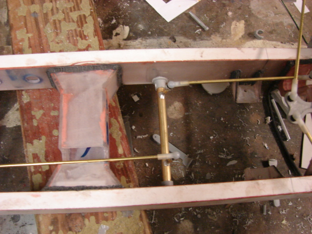
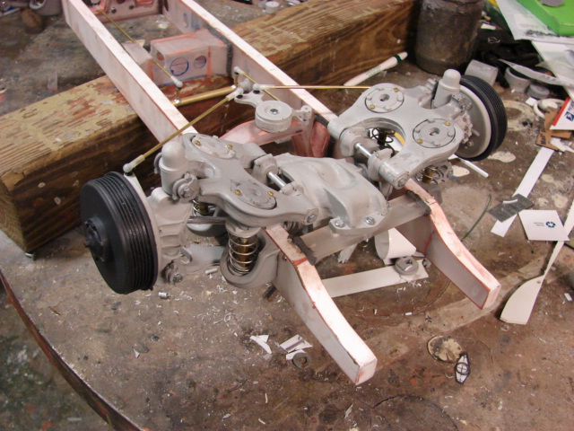
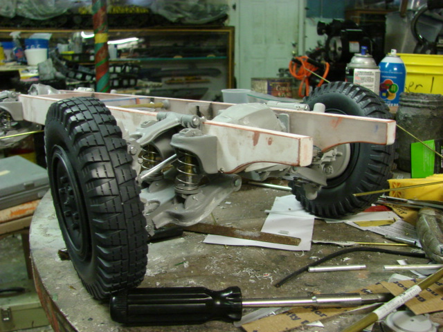
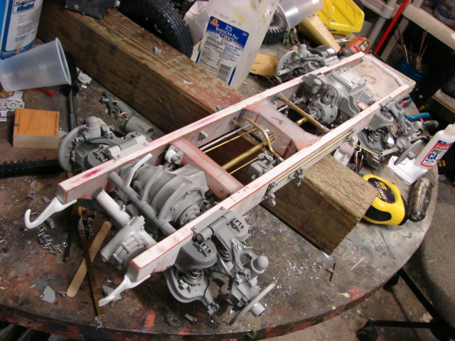
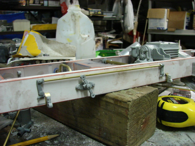
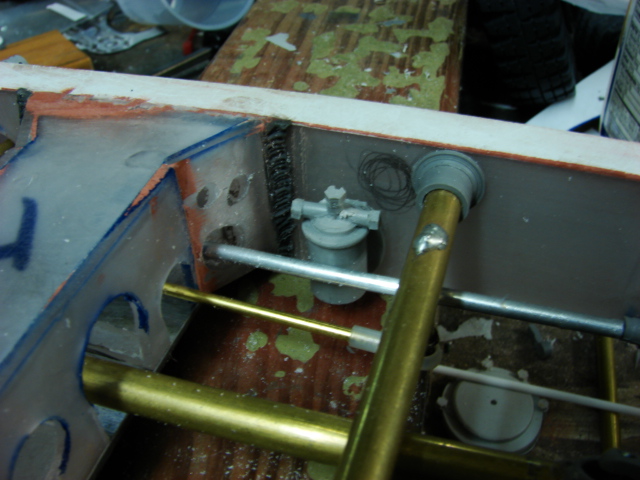
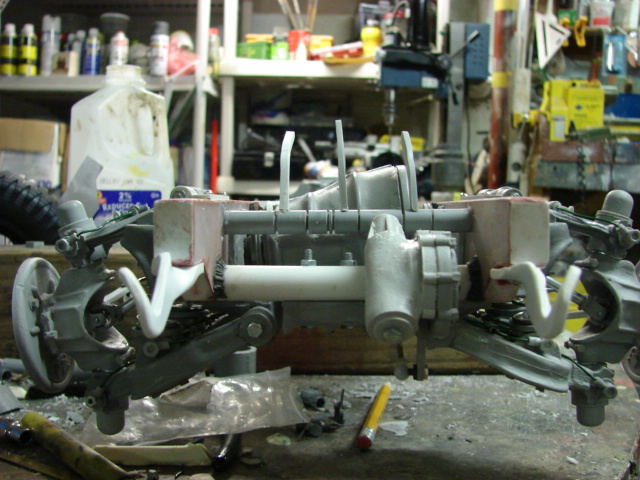
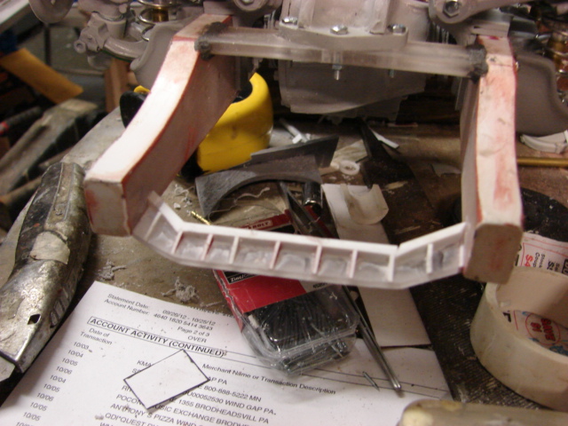
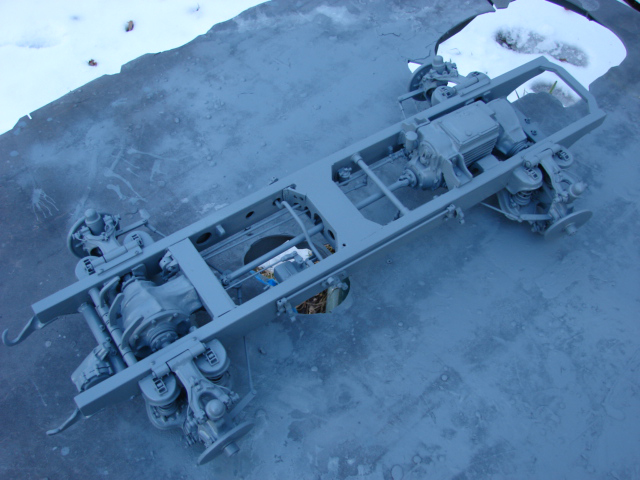
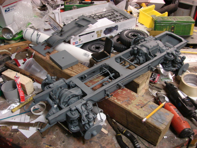
After the frame sides were widened, It was time to assemble the box frame. Because the alignment was very important I utilized tow squares as a framing and alignment jig so when I add the center bulkheads everything would stay square.

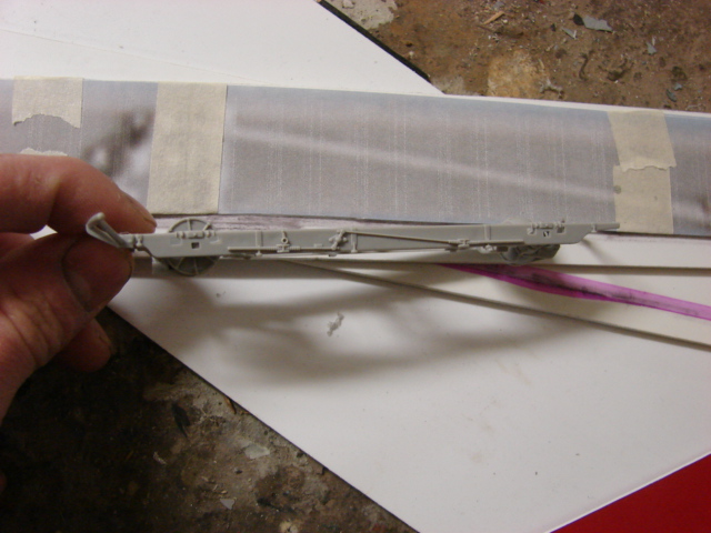
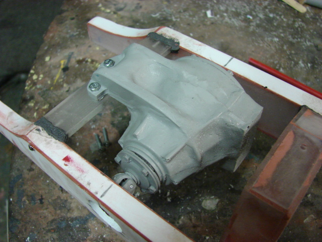
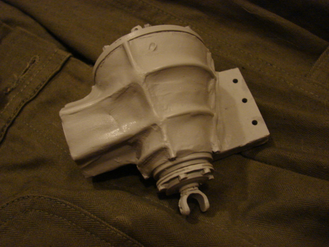
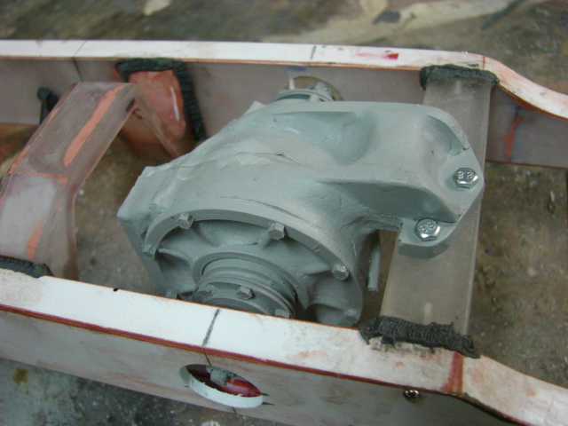
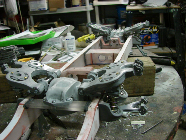
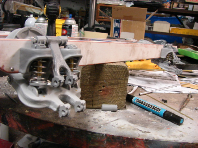
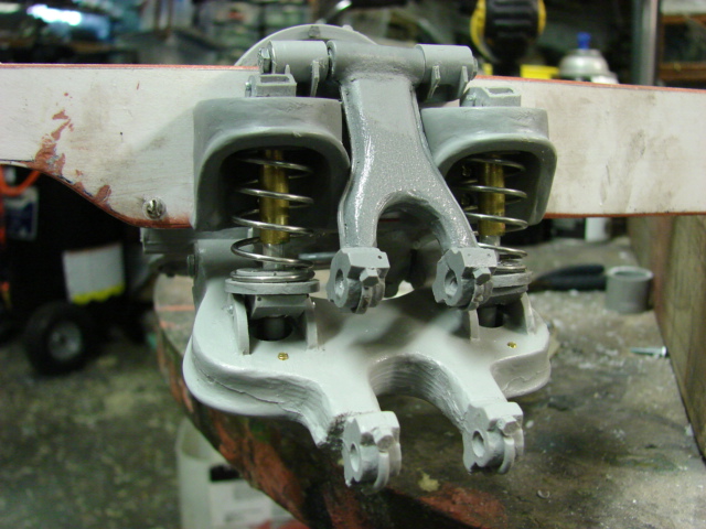
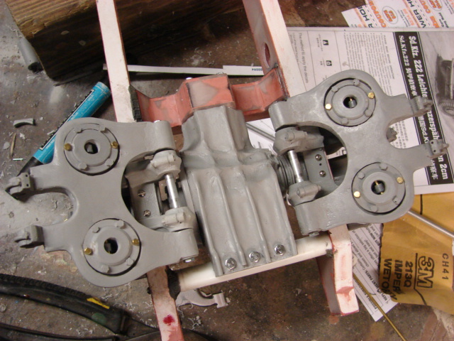
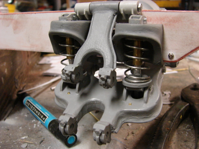
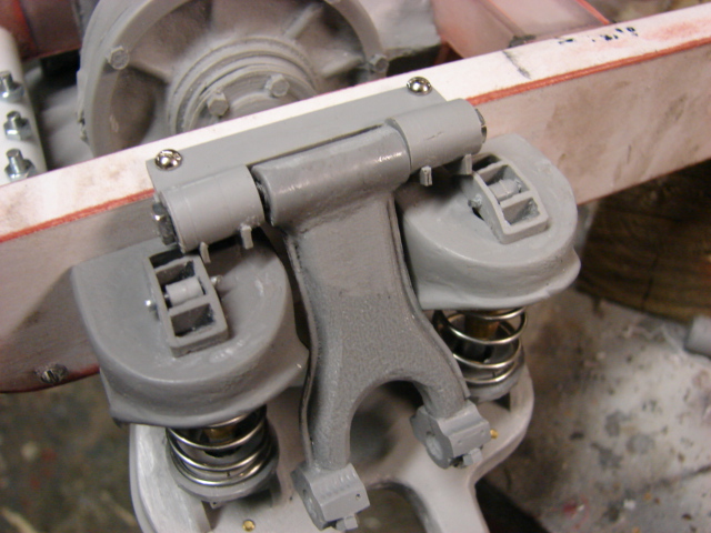
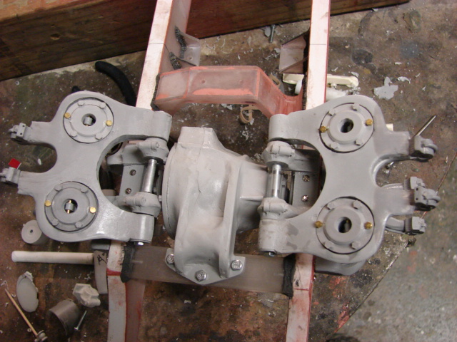
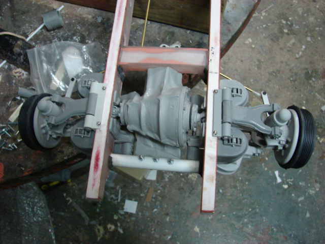
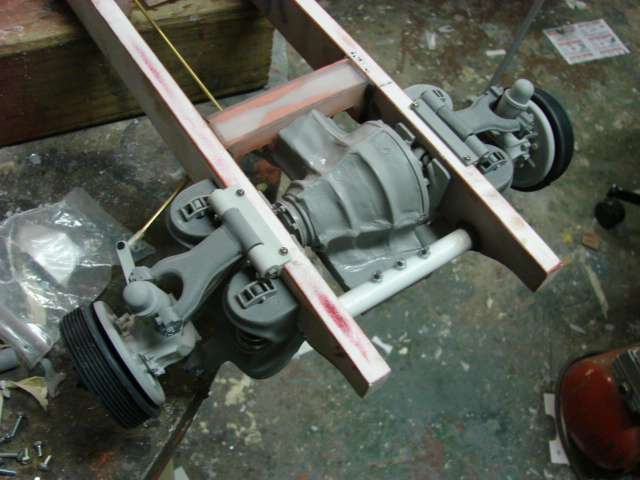
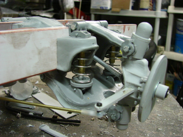
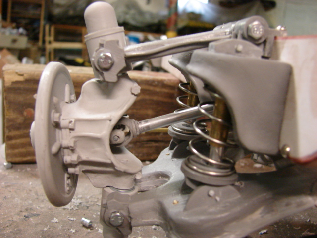
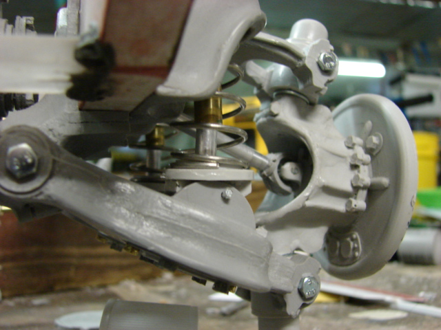
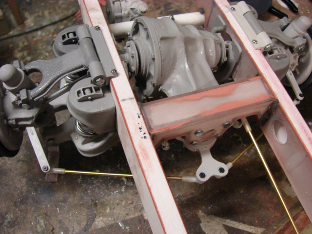
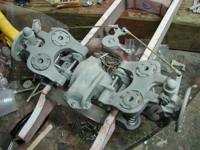
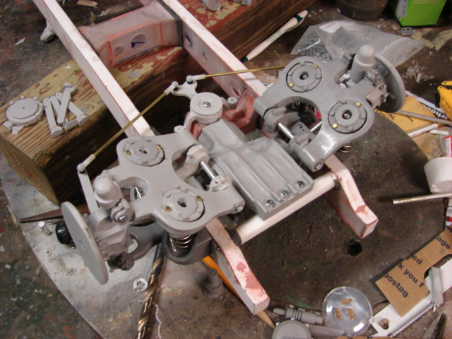
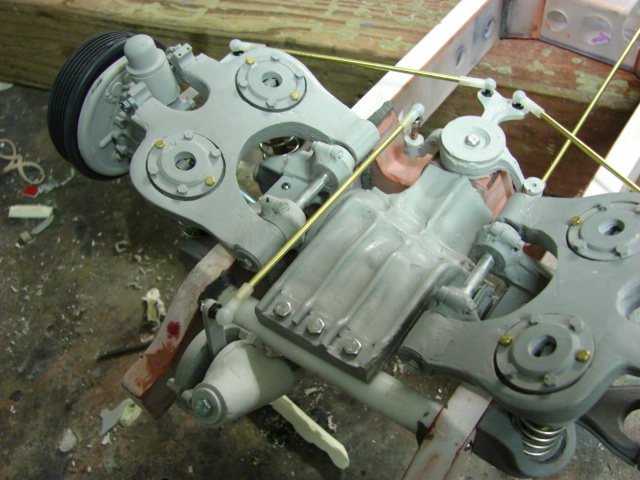
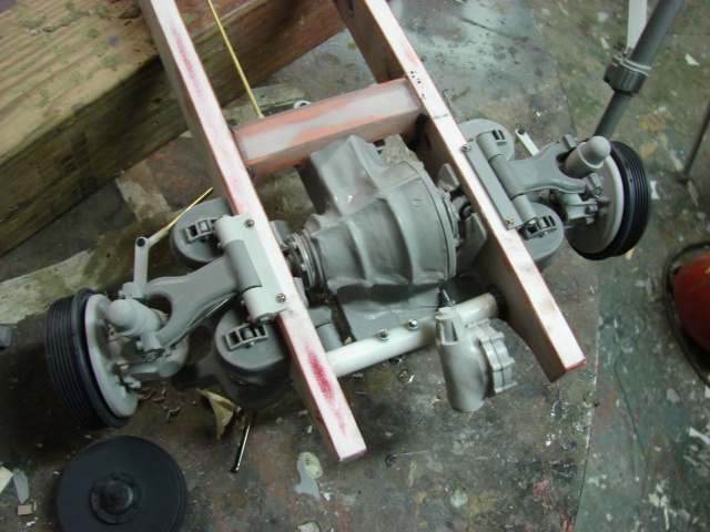
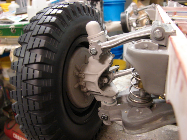
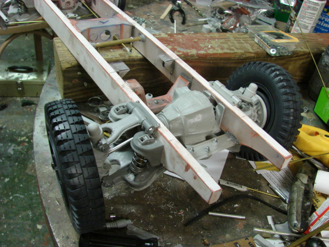
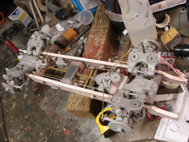
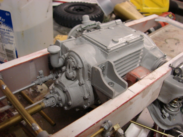
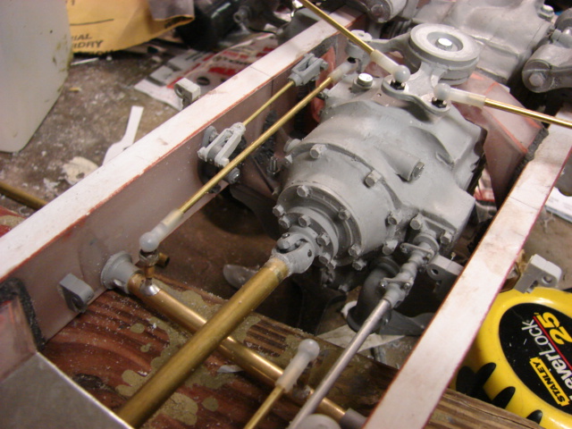
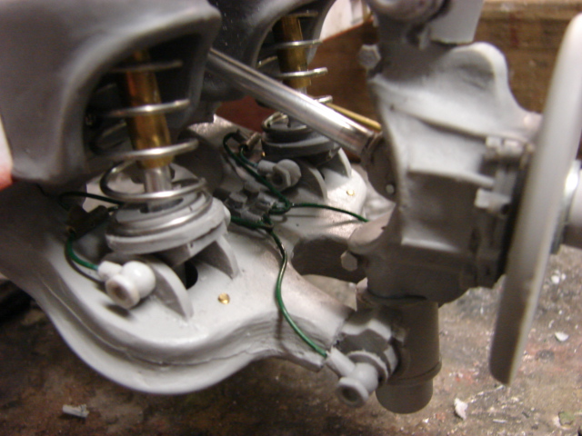
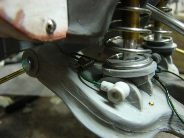
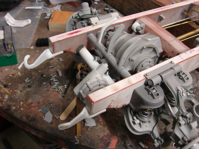
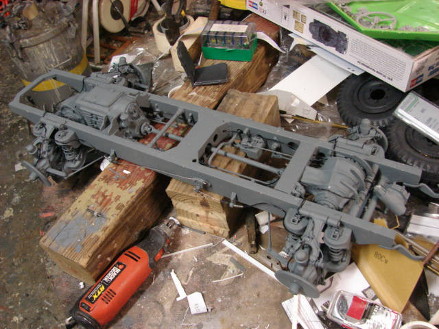
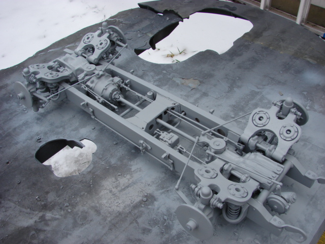
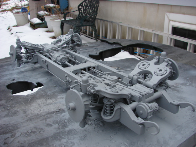
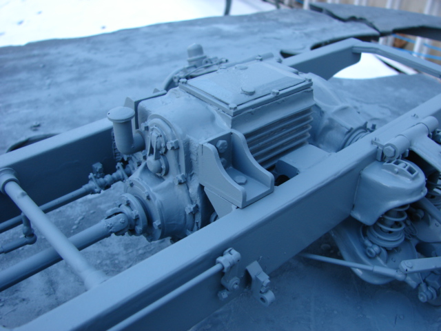
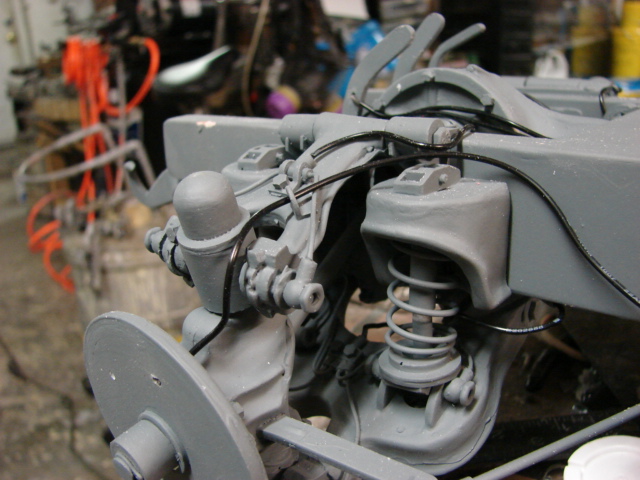
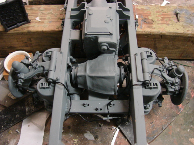
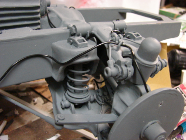
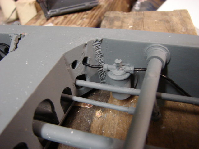
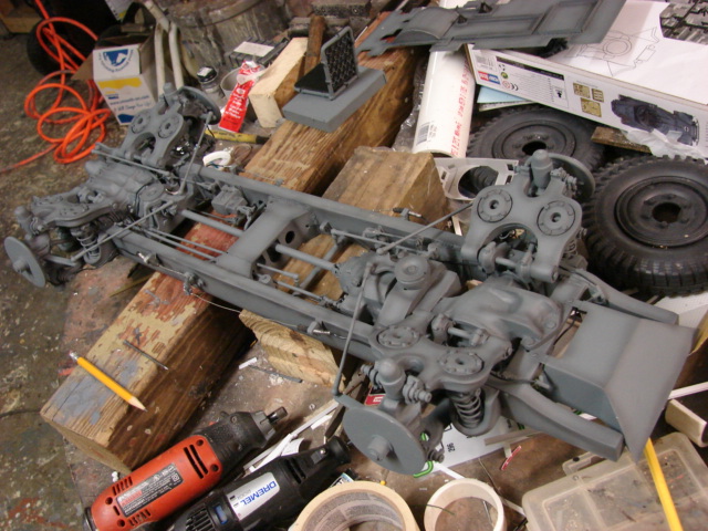
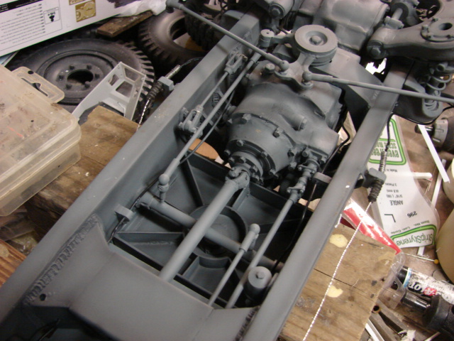
Once the first two supports were added it was time to create the frame’s differential mounts and transmission mounts. After all the mounts were added welds were sculpted onto the parts for detail, seem removal, and for a little more structure. All of the mounts are scratch built out of lexan and are not included with the kit.

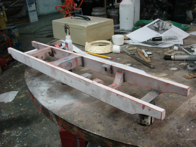
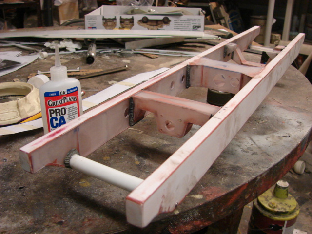
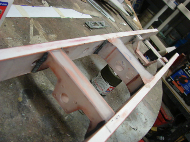
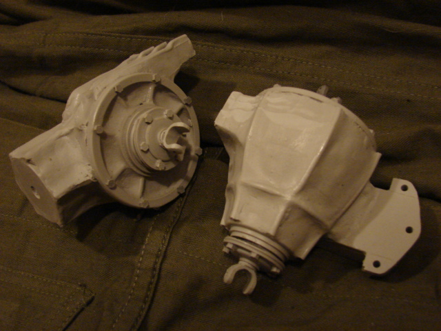
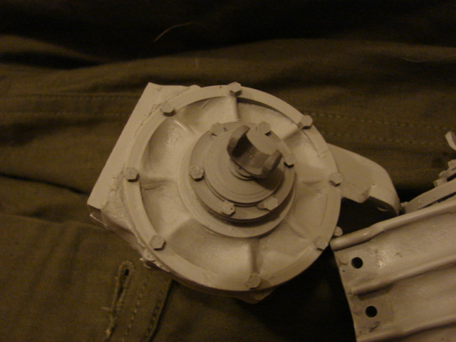
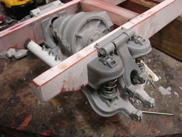
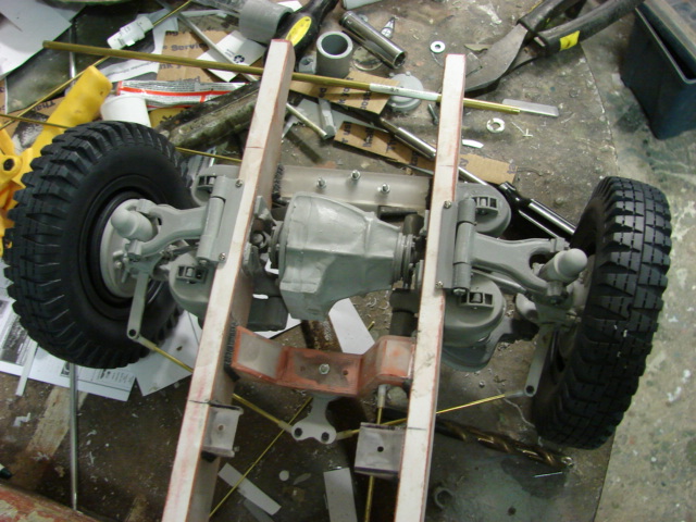
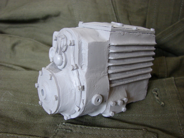
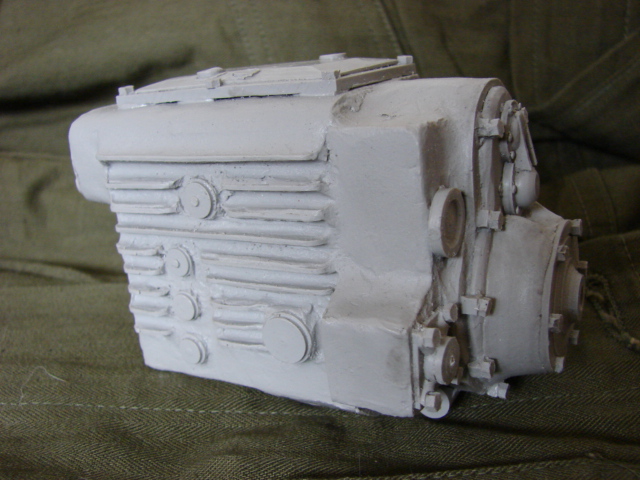
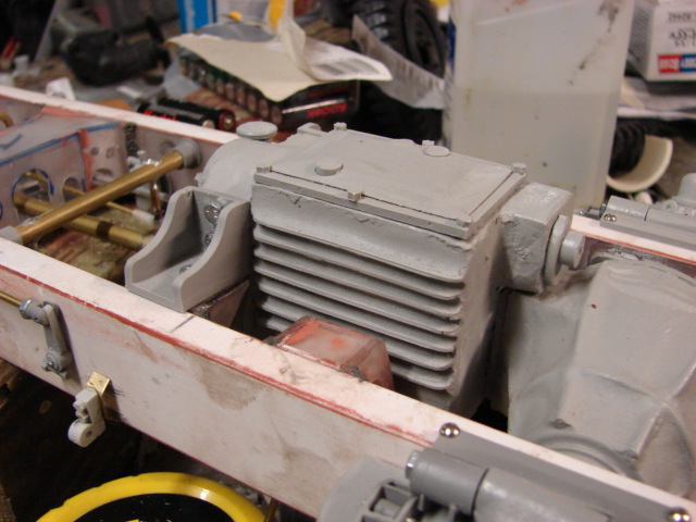
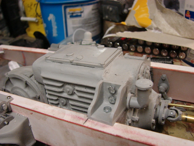
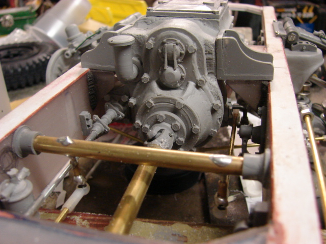
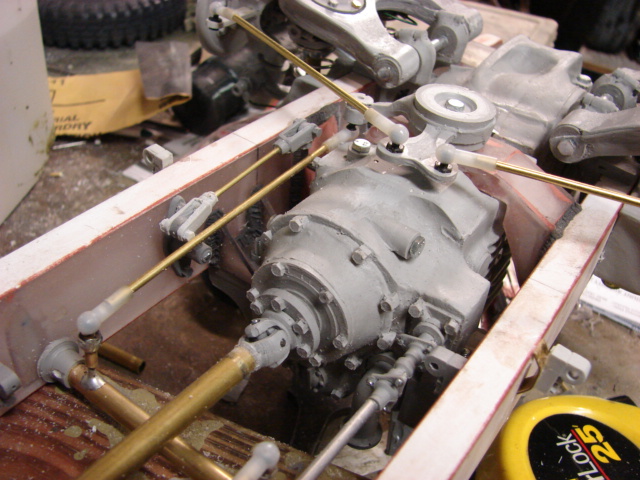
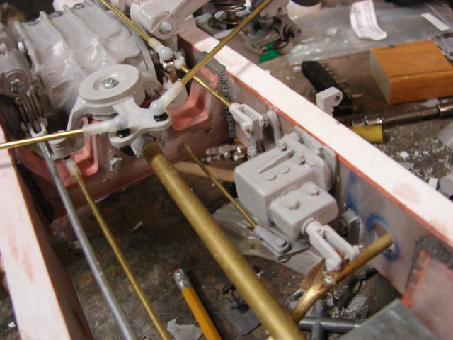
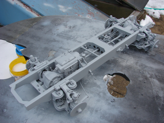
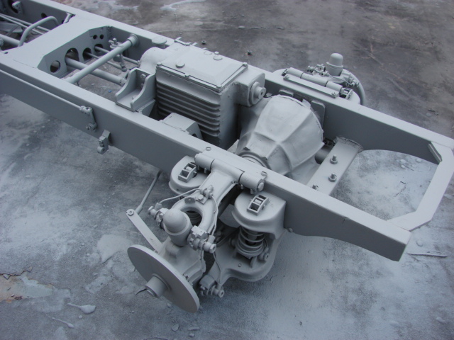
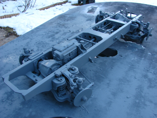
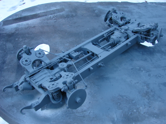
Now with the basic frame complete I can now tool up the differentials and the transmission.

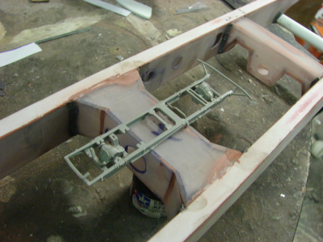
Another youtube video was created which describes the work done to the chassis more in detail. http://youtu.be/PPXNVYgm1C0

More images of the build were also added to the facebook page, http://www.facebook.com/media/set/?set=a.132037110290341.26136.125690767591642&type=1

more to come!

Have never seen any of these before. Looks like quite a project!

Mike

great job on the chassis!

Thanks guys, It’s been awhile since my last post but I have been working on tooling up the model’s suspension. I have completed the model’s differentials and have added them to the newly created SDKFZ 222 product line. www.eastcoastarmory.com/222.htm

I made both the front and rear differentials. I made the spindles spin and the universal joints functional as well. This was done so when the functional suspension is made the drive shafts will pivot all together.

A youtube video was created describing how they mount to the hull, and the way they connect to the transmission and drive train. http://youtu.be/0SD_f_beTKI

I’m now working on tooling up the swing arms. I already ordered some nice wheels from panzerwerk. Once the swing arms are done I will post another update. More to come!

Stop teasing us. Let’s see the bottle of glue that came with it! [:D]

I can’t wait to see it finished.

Dunno if you’re into aircraft too or not but I was checking out this 1/5 scale stuka today http://www.rlm.at/cont/gal17_e.htm

Holy crow! Talk about an ambitious project! Looks like you’re tackling it with vigor though!

wow that is going to be one impressive project.

Thanks guys, I’m not into RC airplanes but they are cool…especially if you are good at flying.

it’s been a while since I had any progress…but I have been working on the model’s functional suspension.

I have completed the swing arms and mounted them to the vehicle.

Unlike the Puma which uses leaf springs the 222 suspension was easier to make functional because it uses coil springs. The 222’s suspension is also simpler to mount because it uses four suspension clusters as opposed to the eight of the puma.

While tooling up the 222 suspension parts I used lots of tricks and improvements that I learned from tooling up the Pumas suspension that I did a few years ago

The 222’s suspension were comprised of four clusters which contained the swing arms, springs and shock absorbers.

All of the swing arm and spring mounts are mounted to the chassis frame via fasteners and glue. This was done for the extra strength needed for load bearing from the springs.

The two coil springs are what keeps the suspension from sagging, and to keep the springs aligned with the chassis spring mounts they themselves are mounted on swivel plates. The swivel plates rotate on the lower swing arm. This way the springs stay at a 90 degree angle no matter how the swing arm dips or rotates. I don’t believe that this detail / function was added to any other 222 model.

connecting the whole unit together are two smaller shock absorbers that are mounted to the bottom swing arm. These shocks run through the center of the swivel plate, through the center of the springs and are mounted to the top of the chassis spring mount.

the shocks prevent the bottom swing arm from over swinging and keep it contained to the cluster. To secure the shocks to the bottom of the swing arm they are held in place by a retaining cap which is bolted to the bottom portion of the swing arm. the resin retaining cap uses two brass hex bolts to secure the cap to the arm, and the molded in hex bolts are just for detail.

more pics were added to the facebook page http://www.facebook.com/EastCoastArmory?fref=ts

With the swing arms out of the way I can now focus on the steering and wheel hubs. Once complete I will post an update as well as a youtube video. More to follow!

Amazing work, as always a pleasure to look at.

holy cow that looks great!

Thanks guys, the last of the suspension components have been added and the suspension is now complete.

Like the differentials the steering collars were designed to have their u joints functional. This was key to having both the suspension go up and down, but to also steer.

For the steering connections I used brass rods along with metal and nylon ball linkages. the ball and socket linkages were also used on the real vehicle

The steering on this vehicle is very unique. The 222 featured four wheel steering. Unlike the Puma which had two steering wheels the 222 wheels were all controlled by a singe driver.

One unique feature is the steering distribution bar. This bar connects the front steering with the rear steering.

Basically this bar inverts the throw of the rear wheels, so when the front wheels are turned the rear wheels turn in the opposite direction, which will give you tighter turns.

In addition to the four wheel steering I also tooled up the 222 steering column.

The steering column is designed to be able to pivot along with the suspension/

Both the steering column and the suspension have been added to the part listings East Coast Armory – 1/6th scaleSDKFZ 222 armored car detail upgrades.

In addition to mounting the suspension I also worked on the fitting of the 222’s wheels.

For the wheels I used the resin early 222 wheels from Panzerwerk.

The panzerwerk wheels are simply excellent!

To mount the panzerwerk wheels to the suspension I modified the Panzerwerk brake drum to accept a new machined bushing. The bushing is retained to the suspension via a machined steel rod and a spring washer.

The system allows the wheels to spin freely, but prevents them from falling off

The wheels will be mounted and assembled after both the wheels and the suspension are fully painted.

A youtube video update was created which shows the suspension’s function more in detail. 1/6th scale German SDKFZ 222 armored car project video #4 (working suspension complete) - YouTube

more images were also added to the ECA facebook page, http://www.facebook.com/EastCoastArmory

With the suspension out of the way I can now focus on the transmission . I also already have the lubrication, and braking system master complete. Once complete they will be added to the model and the product line. More progress to follow, stay tuned!

I have made more progress on the 222’s chassis.

The transmission casing has been installed, and added to the catalog. http://www.eastcoastarmory.com/222.htm

the transmission connects to the front differential via a long drive shaft that runs through the length if the chassis.

The smaller rod that runs along the the drive shaft is the shifter. This rod connects to the stick shift and is what allows you to change through the gears.

The armored car’s breaking system was also partially added. The 222 had both a hand break and regular driving break. Once the chassis get’s it’s base coat the rest of the cables will be mounted. Because of all of the equipment on the interior of the chassis, the breaking system must run through the exterior of the chassis frame

The hand break is located in the transmission housing, and is controlled via a hand lever in the driver’s station. The hand break connections are done via a solid connection.

The break pedal, Accelerator, and the clutch are all mounted together on a bar. This bar is located below the floor boards.
All of the pedals, stick shift, and hand break lever will be added after the installation of the floor boards.

For the breaking system the pedal is connected to a hydraulic box which in turn is connected to a horizontal bar. This horizontal bar is connected to the pulley cable system…which is then connects to the wheels.

Another hydraulic system that the 222 had and was mounted was the lubrication system. The 222’s suspension has many lube points and rather than having a zerk fitting for all of these points the 222 had plumbing lines that connected to all of these locations. This way all of the joints would the needed lubrication.

All of these lines would Y off to their needed locations.

For the bottom set of swing arms the plumbing would diverge into 4 channels. The two would go to the pivot points on the bottom swing arm, while the other two would separate again and would connect to the spring level shelf. Both shelves received these lines.

The oil reservoir is found behind the main bulkhead

On the lower chassis main bulkhead I added a steel plate which is found on the real vehicle. The plate covers the gap that is cut into the bulkhead for the driveshaft, and other connection rods. This plate prevents foreign objects from entering the space and causing problems.

On the front of the vehicle I mounted the front tow shackles

The tow hooks were the stock kits ones, and were reworked. The stock kit hexagonal appearance was smoothed out via a dremel. After the shape was rounded off I heated the hooks with a heat gun, and bent the hooks to shape.

Once the hooks were bent they were bolted to the chassis.

The rear frame bulk head / engine mount was added. The bulkhead is all fabricated out of lexan, and styrene

Like the break lines I will be adding the control lines and the rest of the lube plumbing after the chassis is painted.

The break lines and the lube lines set will also be added to the catalog once the lines are completed.

A youtube video was created showing the progress
http://youtu.be/96fZa3cDURY

More pics were posted to the ECA facebook page
http://www.facebook.com/EastCoastArmory

I will now be assembling the upper hull. Once the upper hull is assembled I can then focus on the interior and engine detailing. More to come!

That’s some seriously brilliant modelling. Terry

At this point its almost like you’r building a full scale car! Now all you have to do is add diesel.

If you actually get the guns to fire I will figure “now I’v seen it all” and will promptly throw myself into oncoming traffic! Can’t wait for you’r next update…

Thanks guys, I made more progress on the model’s body panels.

The body itself was assembled out of the panels that come with the kit, to aid in the construction I labeled all of the panels. without the labeling it would be very easy to get disorientated when assembling

To assemble the panels I used glue, wire, tape…and patience.

To help out with the structure I drilled small holes into the corresponding points on the small panels. floral wire was then inserted into these holes. With the floral wire I can bend the panels to shape and act as a jig to hold everything together while the glues set.

After the glues set I sanded off all of the rough and overhanging edges with a palm sander to smooth everything out. After the panels were all squared off I used putty and epoxy to fill any gaps that were left behind in the panel gaps.

The panels for the elevated front portion are also included with the set. Before mounting these panels I marked, and removed the section from the roof where these panels are mounted.

On the lower portion of the armored hull, there are recess wells that allow clearance for the swing arms. These wells are present on all four wheel locations. The wells are fabricated out of lexan and styrene.

Finally to mount the cab to the frame I had to fabricate the mounting system. The 222’s body mounts to the frame via several small clamps. The clamps mount to the hull, the strap to the frame via a plate and two nuts.

The mounts are all fabricated out of sheet metal and are all soldered together.

more pics have been added to the facebook page http://www.facebook.com/EastCoastArmory, and a video update was also added to youtube. http://youtu.be/tfUxcyY5G_k

I’ve currently been working on the floor boards, and I will be adding the base coat to the chassis. Once the chassis is painted the last of the plumbing will be added…More to come!

I was able to make more progress to the model.

With the basic body assembled I turned my attention back to the chassis frame. Before I was to progress any further I put the frame through it’s painting processes. Because of all of the nooks and cranny’s that are present on the frame, painting the frame at this point will ensure that all of the frame is completely covered in paint.

Starting with the primer

The by it’s base coat of Panzer Grey

After the frame was painted it was time to add the last of the break lines and lube plumbing lines.

Both sets have also been added to the catalog http://eastcoastarmory.com/222.htm

For the break lines the 222’s breaking control lines were facilitated via steel cables that ran exposed on the exterior portion of the frame. These cables would exit from the yolk and would be guided to the four brake drums

where the lines enter their guides they are protected via a rubber boot, on the set I used pre-tinted flexible resin for these parts. Because of this material the parts have their natural “rubber” look to them and don’t need to be painted.

After all of the lines were added It was time to fabricate the model’s floor boards.

For the floor boards I used sheet stryrene for the base and vacuum formed sheet styrene diamond plate for the surfaces. Clearances were cut into the floor boards for the hull mounting brackets, pedals, control stick levers, rocker arm wells, and the front differential.

On the real 222 the front differential a hump was covered by a sheet metal hump. On the model I also used Sheet metal for the part which was soldered together and mounted to the plastic floor board. In addition to the hump all of the equipment mounts were fabricated out of styrene rod and angle.

For the drivers seat I used the resin German AFV seat from panzerwerk. The seat was assembled and had mounts fitted so that it will fit onto the seat mounting rails on the floor board.

Before I can mount the seat to the floor boards I need to paint the floor boards and the seat. After they are painted and mounted I will be focusing on the gun mount hard point, and the interior detailing of the fighting compartment.

More pics were posted to the face book page, http://www.facebook.com/EastCoastArmory

More progress to follow!

awesome details

Thanks Shawn,

I made some more progress on the build. 
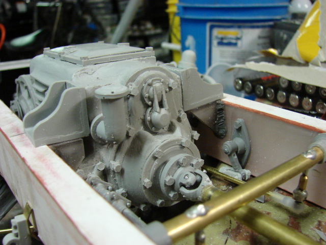
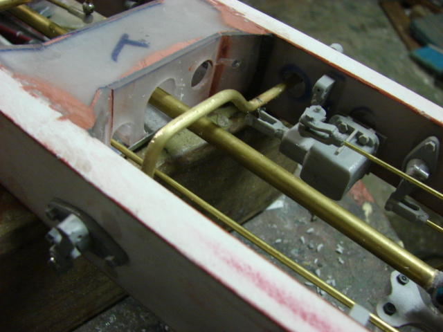
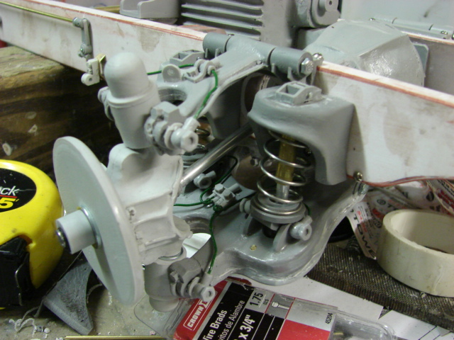
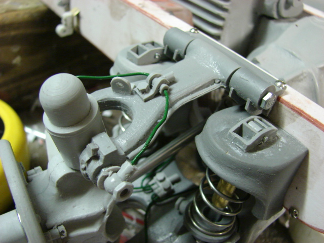
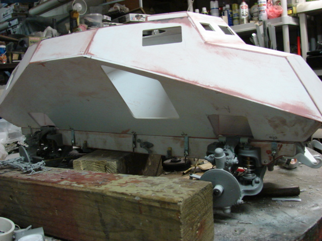
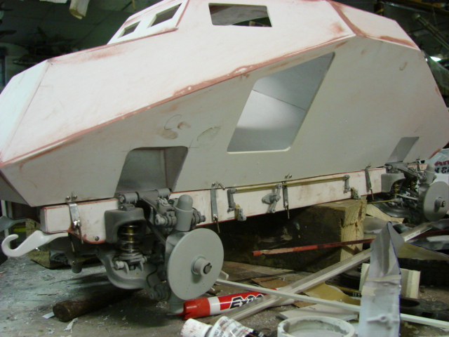
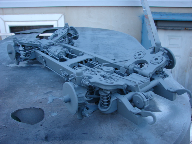
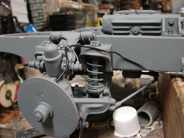
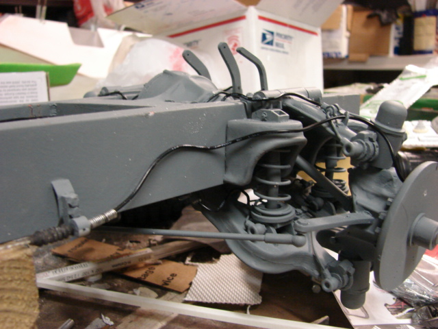
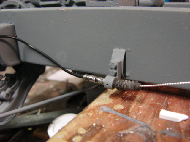
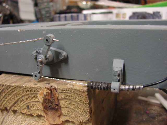
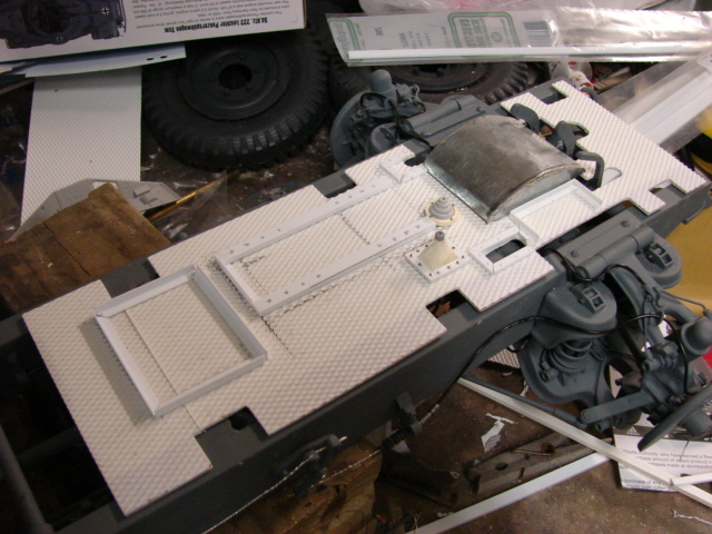
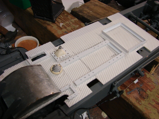
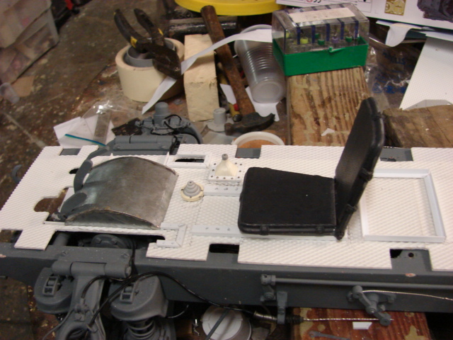
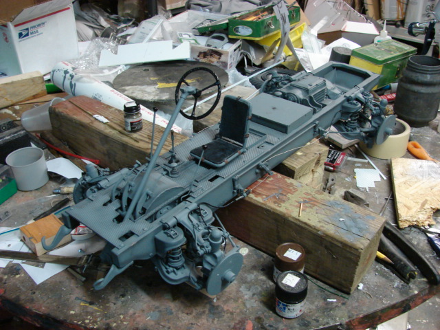
Since the last update the floor boards were painted and weathered along with the chassis.
The pedals, control sticks, and steering column were all added. 
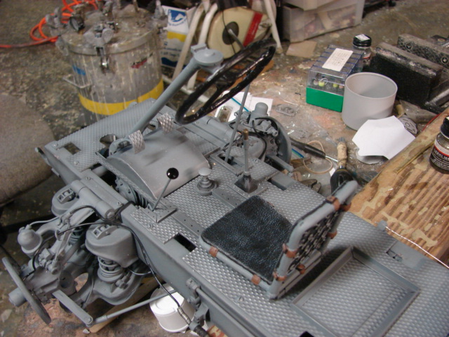
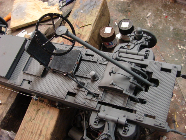
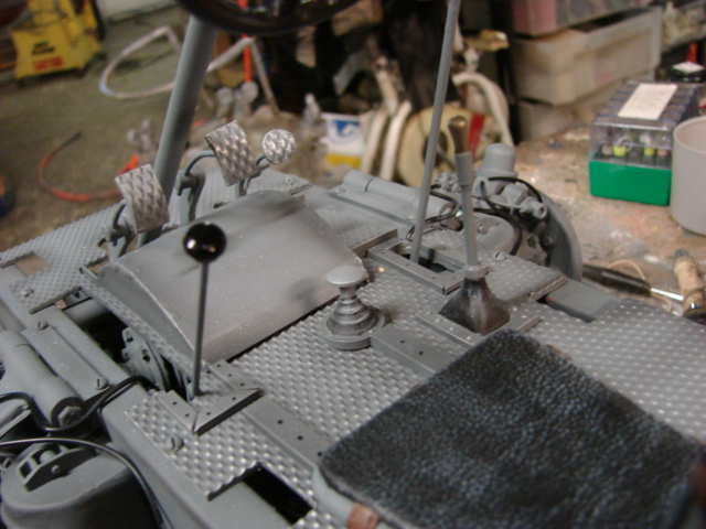
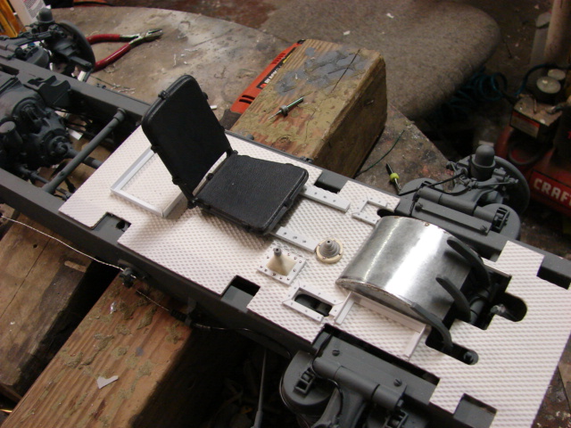
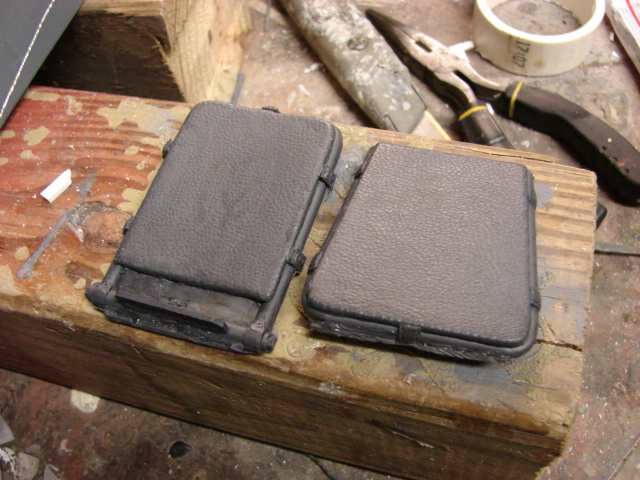
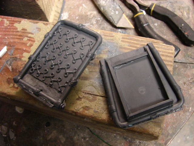
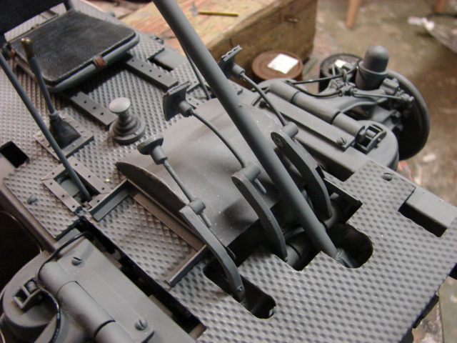
The seat was also painted and weathered. 
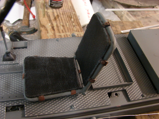
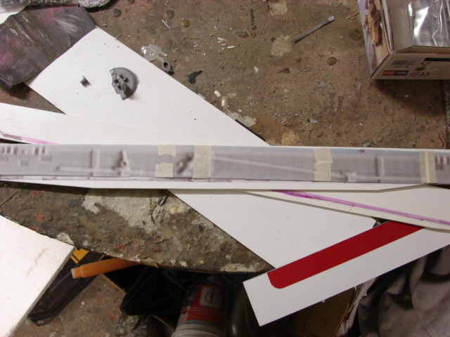
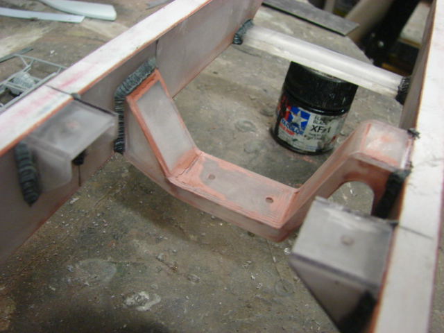
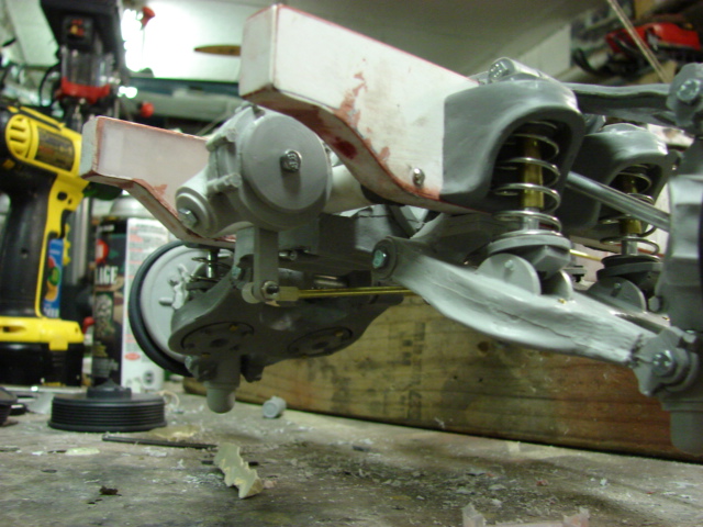
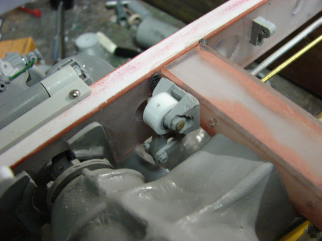
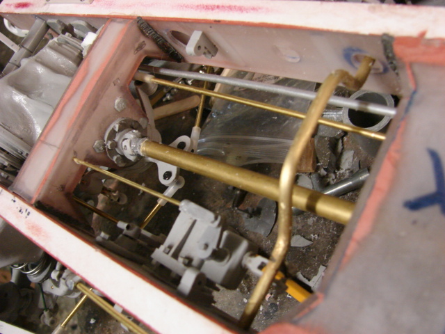
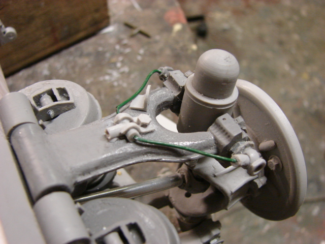
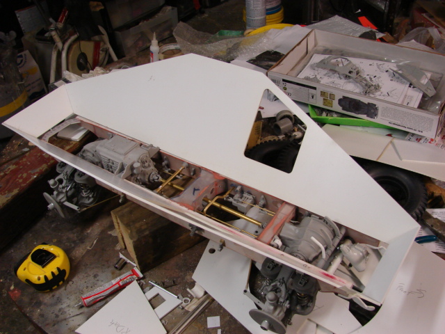
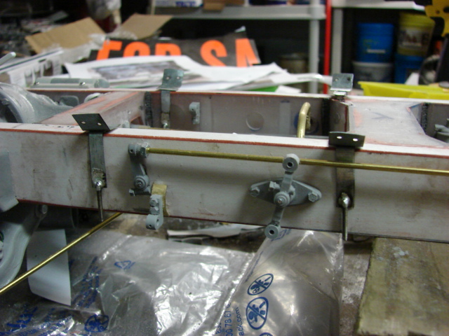
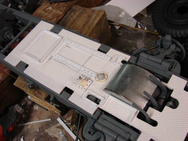
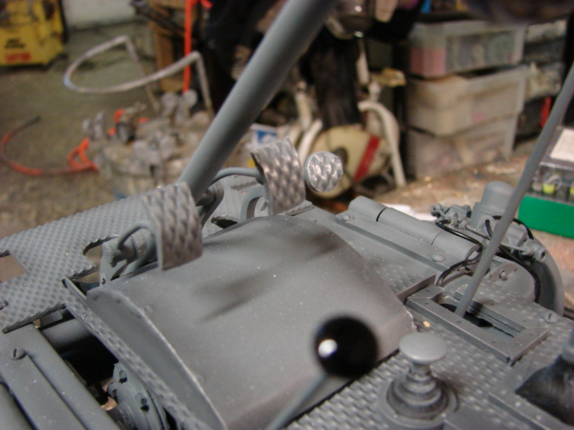
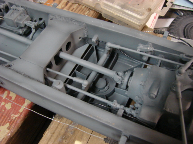
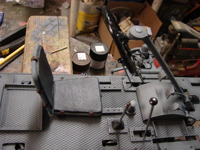
Mounted just behind the driver’s station is where the gun mount will be mounted. To mount the gun to the chassis this is done via a mounting hard point. The hard point is a strong mounting surface that gets mounted to the chassis. The bottom portion of the mount is reinforced with bulk heads, and the top portion will be covered with diamond plate after the cab get mounted. The component itself is fabricated out of lexan and styrene. After the part was painted / weathered it was mounted to the chassis 
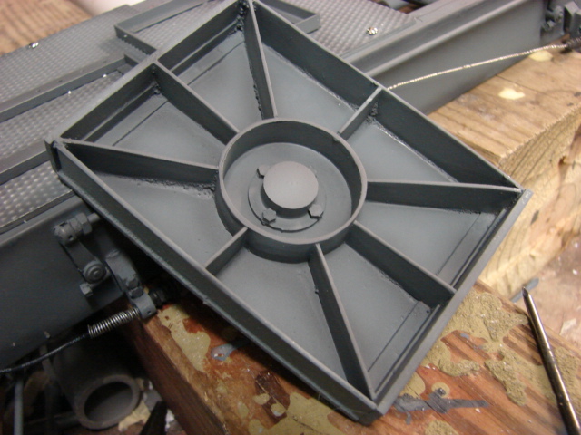
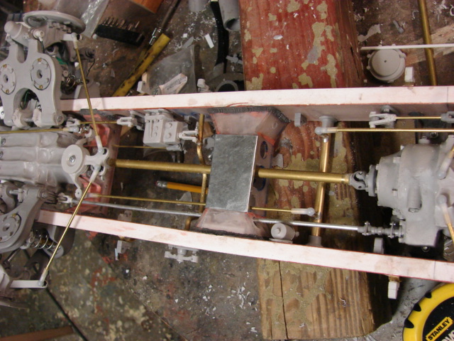
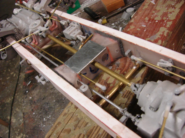
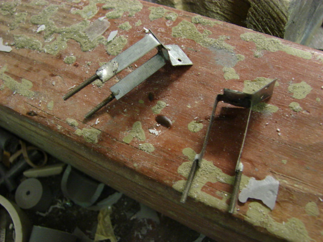
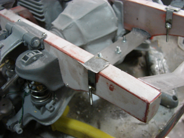
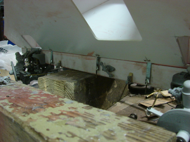
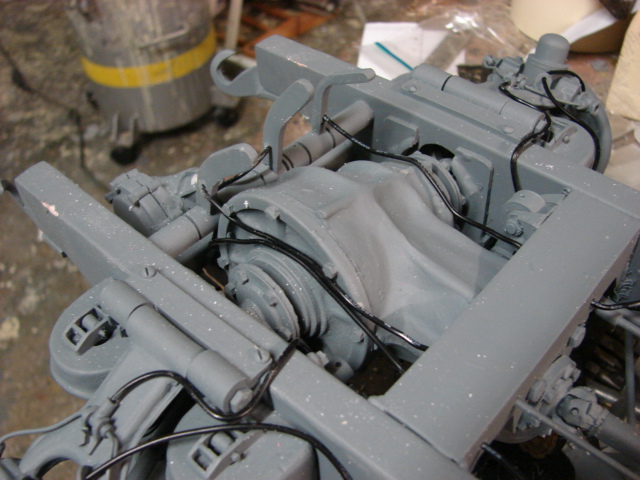
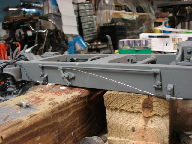
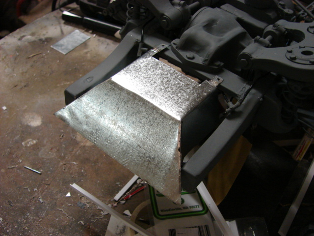
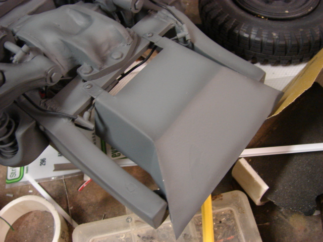
On the rear portion of the hull a sid plate was fabricated and mounted to the chassis. The skid plate protects the engine from damage. The plate itself is all fabricated out of sheet metal.
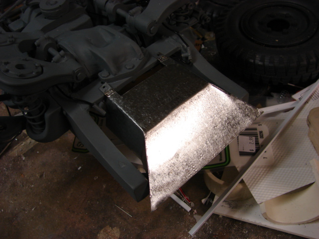
 A

youtube update video was made and explains more of the progress. Also more images were added to the facebook page
http://www.facebook.com/EastCoastArmory

http://youtu.be/4bVIPgqdfSM

with the driver’s station now complete, I have now turned my attention to the interior of the cabin. Once complete the cab will be mounted and I can then start on the gun and gun mount. More to come!

Amazing.

Terry.

truly great work