Tony - Thanks for the peek, always a pleasure.
Bufflehead - I am glad to hear you understand the ways of the Redleg!! [;)]. Thanks for the comments and welcome you keeping along with this build. As always, any questions, feel free.
Rounds Complete!!
Tony - Thanks for the peek, always a pleasure.
Bufflehead - I am glad to hear you understand the ways of the Redleg!! [;)]. Thanks for the comments and welcome you keeping along with this build. As always, any questions, feel free.
Rounds Complete!!
Love it Mike, the Alclad stuff really adds to the detail. Nice trick on the wear-inducing procedure on the tires as well.
Always looking good Mike! [Y] Thanks for the tip about Vallejo primer. I am a big fan of Mr Surfacer primer but it is truly pain in @ss to clean the AB at the end. I will order Vallejo primer next time I order something from Squadron.
Bill - Thanks for stopping in. I usually start with a new pad. Once it is a bit worn it moves on to one of the sinks in the house. Having the pad gives good control but not as harsh as sandpaper. great to take off the seam, give some edge wear and generally rough up the tire.
DP - Always great to have you stop by. The Vallejo primer is not as “aggressive” as Mr. Surfacer and is not as “hard” as the lacquer base but…the ease of use, goes right into the AB, sprays on very well, covers well to give a uniform base, and the size and cost will let one jar last a long while and this only pennies per model to prime. If you have to go back it also sands well. It appears to be somewhat self leveling like Future, so a quick spary on the sanded area and when dry is hard to find. Works well on resin, styrene and metal. Lastly, you can clean up with Windex.
Thanks again guys
Rounds Complete!!
With the major assemblies painted it was time to bring the upper and lower carriage together. The barrel and sled was added after working the sled to get it to fit. This assembly is very tight on all the AFV models with this carriage all require some blade and sanding work to fit the parts without breaking the upper carriage I then assembled the breechblock, which I painted with Alclad Steel. With the upper carriage assembled, I added the equilibrators, which were painted on their working section with Alclad Polished Aluminum. Before mounting the upper carriage to the lower, the gear surfaces for elevation and traverse were painted with Alclad Steel After the mating of the two carriages, the front and rear spades were added.
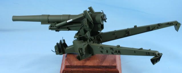
As you can see with the spades mounted the assembly is not stable to work on. With that it was off to the woodwork shop to create a base. After staining and sealing the wood a sheet of Styrofoam is mounted to to create a base to dig a hole in. The photo below shows the Styrofoam with the holes cut to fit the front and rear spades.
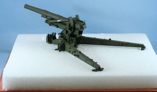
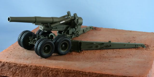
After a coat of Cell-u-clay and a coat of Poly Scale Earth I mounted the howitzer. The holes are filled with Cell-u-clay to form a pile, as the holes would be refilled when the howitzer is actually emplaced. Below you can see the howitzer at this point with the test fit of the bogie section.
After pin washing with MIG Dark Wash and an overall first filter coat with MIG Grey for Green I began working on some details. I finished and mounted the panoramic telescope. Overall painted with Tamiya OD Green, the level bubble, mirror and eye cup painted with Alclad Polished Aluminum, the traverse dial and hand wheels painted with Tamiya Flat Black.
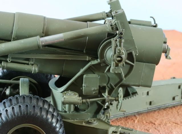
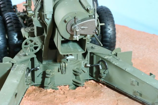
Next it was time for the brakes. I used 26 gauge SS wire to make the strain relief springs and soft 20 gage black wire for the lines to make the connection from the trails to the lower carriage section. Prior to mounting, the molded in brake lines on the trail were painted with a flat black marker and the connector near the back of the trail was painted with Alclad Steel.
This also gives you a good view of the breech. Not seen in this photo is the .020 hole drilled into the firing lock to add a lanyard later.
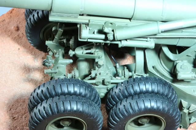
The front brake lines were assembled the same way as above. The back line comes off a pneumatic Tee which I used the Aber Pneumatic Parts PE set to make the Tee which is mounted on the dimple just behind the bogie guide. The front lines required a .020 hole be drilled in either side of the pneumatic control box which is on the front of the lower carriage.
With the boige in place and the brake lines connected, the bogie adjustment screws were added. These were painted OD, dry brushed to raised screw surfaces with Alclad Steel and inside the threads pin washed with MIG Dark Wash. Ware was also put on the head with Alclad Steel. Lastly the travel lock was added and the moving pins were dry brushed with Alclad Steel.
This photo you can see the travel lock in the center of the bogie and one of the rear air lines connected to the brake assembly. You can also see the pneumatic Tee to the right of the travel lock, in the back center of the bogie.
That’s it for now. Time for lots more little details and weathering to come
As always all comments are welcome
Rounds Complete!!
Holy crap - there’s not one thing about that post that I don’t sit here in awe about!
I never had heard about the Alclad stuff before here but it certainly is worth the look at - its all looking great!
Sweet work on all the little details Mike, wouldn’t expect anything less from one of your builds. Look forward to the next round of updates! [Y]
Looking great! [Y] Now it is starting to look like a big gun. I just noticed that it has same lower body as of Long Tom but it has a different barrel, is it? Always wanted to build that…
Chris - Thanks for the comments. Here is where you can get information on Alclad
http://alclad2.com/finishes/regular/
Now…I will warn you…it is a Lacquer paint. It is thinned to use in the AB from the bottle. You have to have ventilation or a spray booth and you have to base coat with an acrylic black and lastly it is expensive…about $8 per jar. Now all that said, IMO, it is the best metallic finish out there.
Bill - Thanks for the peek. Its time for my favorite part of the build…those obscure artillery details!!
Rounds Complete!!
The Big Bang Theory is true,it’s true,it’s true.
Mike you my man of magnum firepower.
Mighty Fine,Mighty Fine
Tony lee
Andy, “Long Tom” was a 155mm gun. When I went through Arty Fire direction school in 1969, this thing was considered the most accruate piece we had. Adjusting fire from a battery of these was easy because there was so little dispersion, and “fire for effect” was a real blast! (pun intended)
Redleg, really great job there! Makes me want to haul out the old FADAC!
Andy - You sneaked in while I was posting!!! Yes the 155mm Long Tom and the 8 inch share the same lower and upper carriage. The only difference is the barrel. They even share the same M5 Limber. The Limber included in the kit is the later version for after WWII. If you want to build the Long Tom for WWII you can get the Masters Production limber and tire set to get you on target. Thanks for the peek
Gene - Both the 8 inch and the 155 Long Tom were known to be very accurate and powerful weapons. It was the reason why the same basic 8 inch made it onto the M43 HMC and then the M110 SP carriage. This basic weapon lasted from WWII thru the 1980s. Thanks for dropping in
Rounds Complete!!
Looking great Mike. The brake lines look really nice. Great job.
Andy - As GeneK says, the “Long Tom” was the 155mm version. The M115 and the M59 shared the same chassis and cradle. The only real difference was the barrel; 155mm on the M59 Long Tom and 203mm (8 inch) on the M115.
Looks like Mike and I were typing at the same time. Great minds think alike. [:D]
Tony - You slipped in…glad you like my big 8 inch…[:|]…[;)]
When you look at the base, it is a 12 x 12 wood base so that will give you and idea of size. Its your kind of build!
Thanks for stopping by.
Rounds Complete!!
Why did the 203 mm have a short barrel when compared to the 155 MM ? It would seem the shorter barrel would tend too have less range of accuracy than the longer barrel .
Great kit and you did a fine build of her .
It’s a matter of kinetic energy.
Geno, Redleg, maybe you remember better than I do, wasn’t the “Long Tom” restricted to low angle fire only? I never really got to work with them.
BLAM it ALL!
!https://encrypted-tbn0.google.com/images?q=tbn:ANd9GcRjmawNzBRoWoPbGhN77w-MNH7gpzft60XK4C932s45aUDmRRZMkA2KThis looks grand…
Now just add some matching dirt color to the tires and a light dusting of the ground color from the latest fire mission and you got it.
Fire for EFFECT !
Gino - Always good to have you on the safety circle…thanks for the peek
Shellback - OK, first difference is the 155mm is a gun and the 8 inch (203mm) is a howitzer. That is to say the 155mm fired on a flat trajectory while the 8 inch fired an arced trajectory. The 155mm could only fire low angle or less than 45 degrees (800 mils) elevation. The howitzer could fire both. High angle fire would allow the 8 inch to sit on one side of a hill and fire over the hill.
The higher caliber barrel (longer barrel at a fixed diameter) for the 155mm caused a higher exit velocity and thus the 155mm had a longer range. The 155mm with the flat trajectory was more susceptible to inaccuracy at long range though both were accurate the 8 inch was the better of the two.
Lastly, the longer barrel, less powder charger per round, smaller & lighter projectile, 155mm, would exert the same recoil force on the carriage as the bigger, more powder, heavier projectile 8 inch. SO…it is a matter of what the equipment could handle.
SOOO…that is a long explanation of saying, they wanted range, the 155mm gun gave them a longer range, 23km. As for wanting punch the 8 inch delivered a 200lb projectile at 18km.
Gene - Thanks for the jump in.
Steve - Thanks for the look. Yep…I have a few little items to add to the howitzer them it is time for a final filter and then DIRT!! Also have to add all the toys around the howitzer…a cannon is no fun unless you have all the proper toys.
Thanks again guys.
Rounds Complete!!
Mike- Thanks! Before I came here, I swear I knew very little about artillery… maybe just ‘Long Tom’, 88, Pak 40… that’s it! Thanks to guys like you I have learned so much about those big guns…
Keep them coming! [B]
Andy - Thanks for the comment…that is the great thing about the site and the diversity of people here. We can all share, teach and learn. It help all of us grow in the hobby.
Rounds Complete!!