Zvesda 1/2700 Star Destroyer with custom lighting

A little more work last night and today.

Lighting test after putting together a few more LEDs

Put together the engine circuit board, that’s separate from the main LEDs, but it shares a connection to the main LED circuit board

Connected together

Then made a test with the LEDS hooked up to the engine housing

And a test run with the Arduino

It works!

Oh wow, she’s really lookin’ good!

Engine lighting done! Only thing left would be to possibly tweak the timing on how the lights ramp or or the color pulsing.

Engine running

Looks good! I like the neat look here, so many the fiber optic cable and wiring look like an explosion in a spagetti factory.

Got some more work done! The last lighting circuit board:

With the IC mounted (TLC 5940NT for those who are curious):

This is going to drive a set of SMD lights, which I spent the weekend mounting and wiring up. These are a joy to work with since the wires for them are 0.2mm thick. Yeah…

This is where one of them get’s mounted in the model

Close up after mounting

It works!

JST connectors where the tiny SMD wires will be soldered to, and then use reasonably sane wires that I can actually work with (without worrying about them evaporating into thin air at the slightest touch) for the rest.

Soldered…

Wired up and ready to go…

It’s alive!!

That is mind blowing!

Ive wired up a couple of small kits, but this is by and LARGE the coolest build I’ve ever seen lit up.

Fanfreakintastic!

Yeah, she’s looking amazing!

Cool!

So you used the TI chip for doing shift registers and controlling blocks of LEDs? I’ve read about that but not tried it. How challenging was it to program on the Arduino?

Yes. I have a total of 28 leds for main body (upper and lower halves) & tower, 7 more SMD lights in the lower body, 1 light box for indirect lighting of docking bays, 7 for the engines, and 1 for the tower garbage chute. So thats 44 total. The main body and engine LEDs are driven together (they are neopixel LEDs). The 7 SMDs, garbage chute, and lightbox are driven by the TI chip.

Both sets have code that instead of simply just turning them on or off, gradually ramps up to full color intensity over the space of about 300-500 millseconds (and in the case of the engines actually flickers the color over time as they are on).

Pretty easy. The Arduino IDE works great in terms of seamlessly uploading your compiled code to the actual Arduino hardware. The IDE is simple, but then again the programming is crazy complex either, so it’s OK.

Got the lights for hte tower wired up, simple test…

Can’t argue with that. Arduino’s are geat little devices.

Had some fun once coding up a homemade laser tag set. Complete with Ammo count, Health bars, and sound effects. Kids had fun with that but discovered TV IR remotes were like nukes and could aim practically anywhere in the room and get a hit. [:D]

Your build is going to look awesome when completed!

More progress… bottom half and engines all wired up and hooked into the circuit boards. Yikes, no turning back now…

Ok I do believe the little engines are not supposed to be on when the mains are on. They were not lit on the original filming model. Good probability those engines are for light speed not really sure unless someone has the schematics laying around for Star Destroyers?

Thanks for the info, sorry for the long delay. Finally solved the remaing electronics isues (hopefully all of them now), and made some more progress. The bluetooth controller is now sorted out, so I’ll be able to control various bits, including the start up of the light speed engines vs the sublight. Not sure if the big ones are lightspeed or sublight, will have to look that up.

Ok finally some more progress, battery supplies hopefully sorted. Assuming I did this right I’ll be powering this with ~12v ~2.2A, with a battery pack of 3 18650 cells, and if I attach it all up correctly hopefully it won’t burn down my apartment!

So this showing the separate battery cell holders, spaced individually instead of all together to allow everything to fit.

the Battery Management System, this makes sure the battery drain is kept even and handles the logic to properly recharge them as well.

Little on board voltage meter, press the button and it will show the battery voltage, to see when it needs charging.
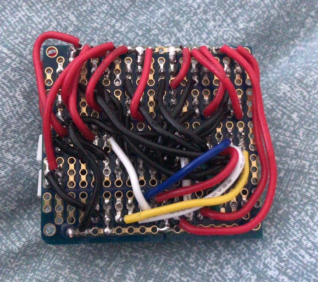
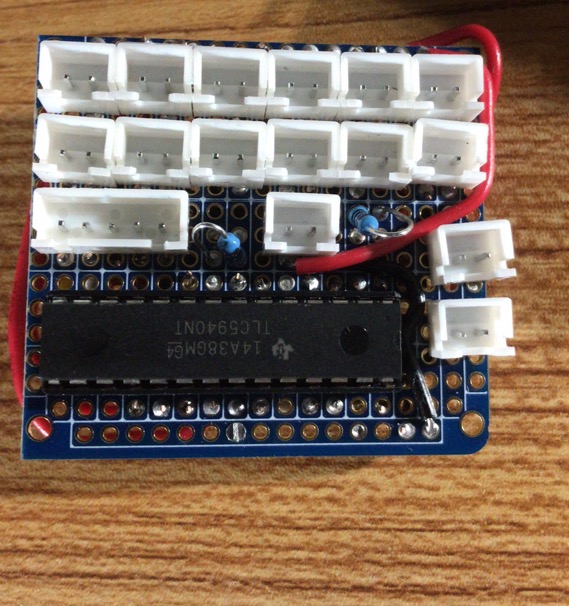
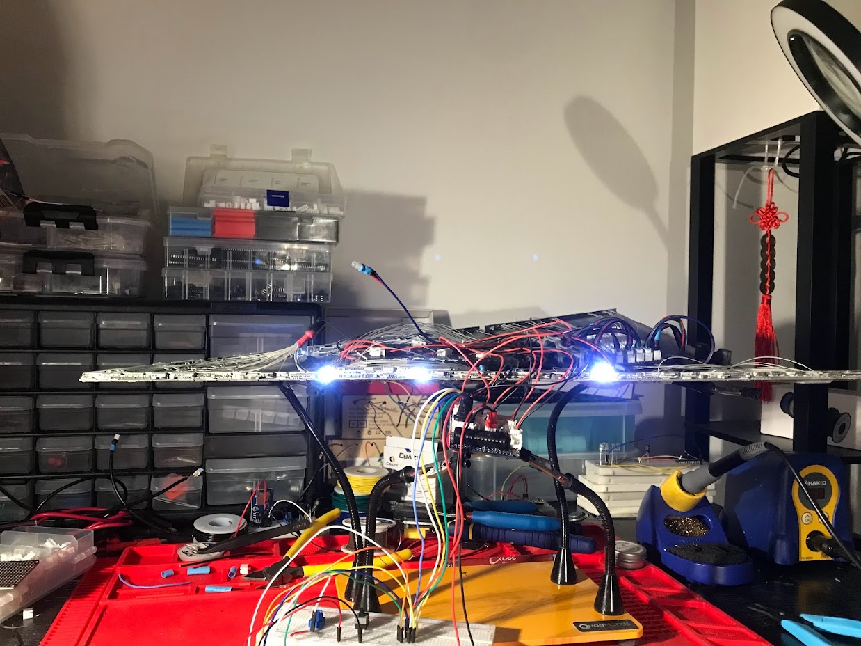
component placement

and after mounting and wiring up for good:

The Bluetooth controller lives!

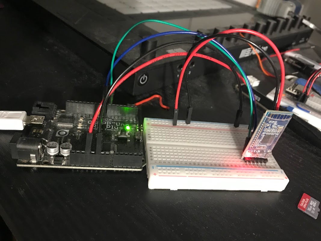
Test rig for the bluetooth controller,
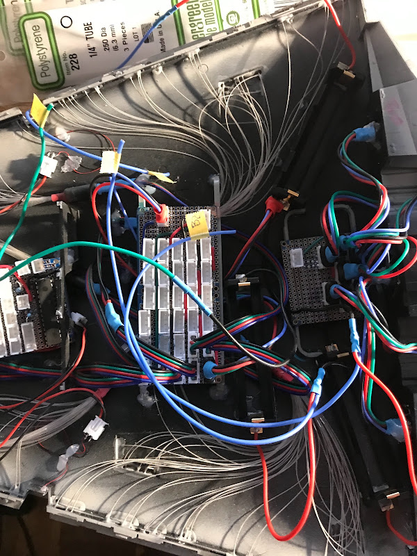
wired up for real

It talks to this program (test app on my MacBook that will then get ported to iOS for usage on iphone):

And when the two are connected the controller outputs this on windows (when the arduino is connected via USB):

Arduino pro mini mount:

Not done yet, just have the power/gnd leads in place

Audio board to place sounds and imperial march

That’s all done now, it will be connected to above arduino board.

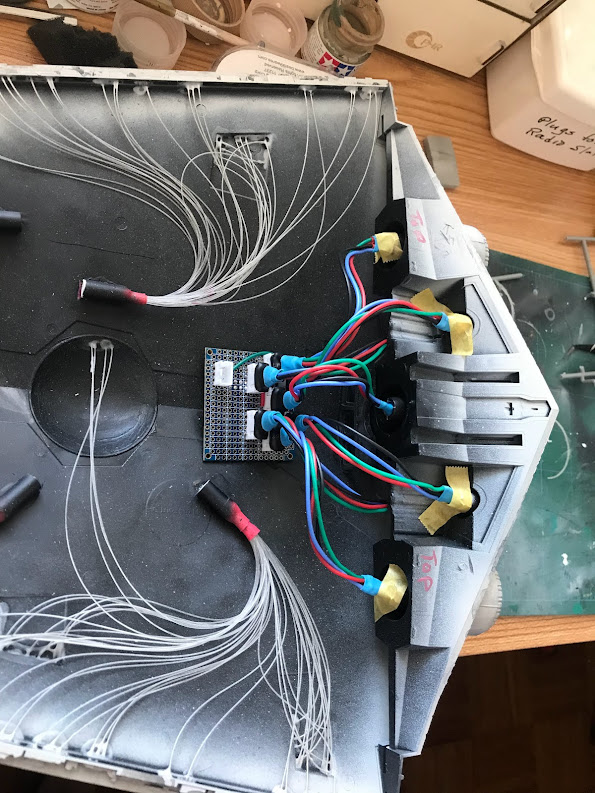
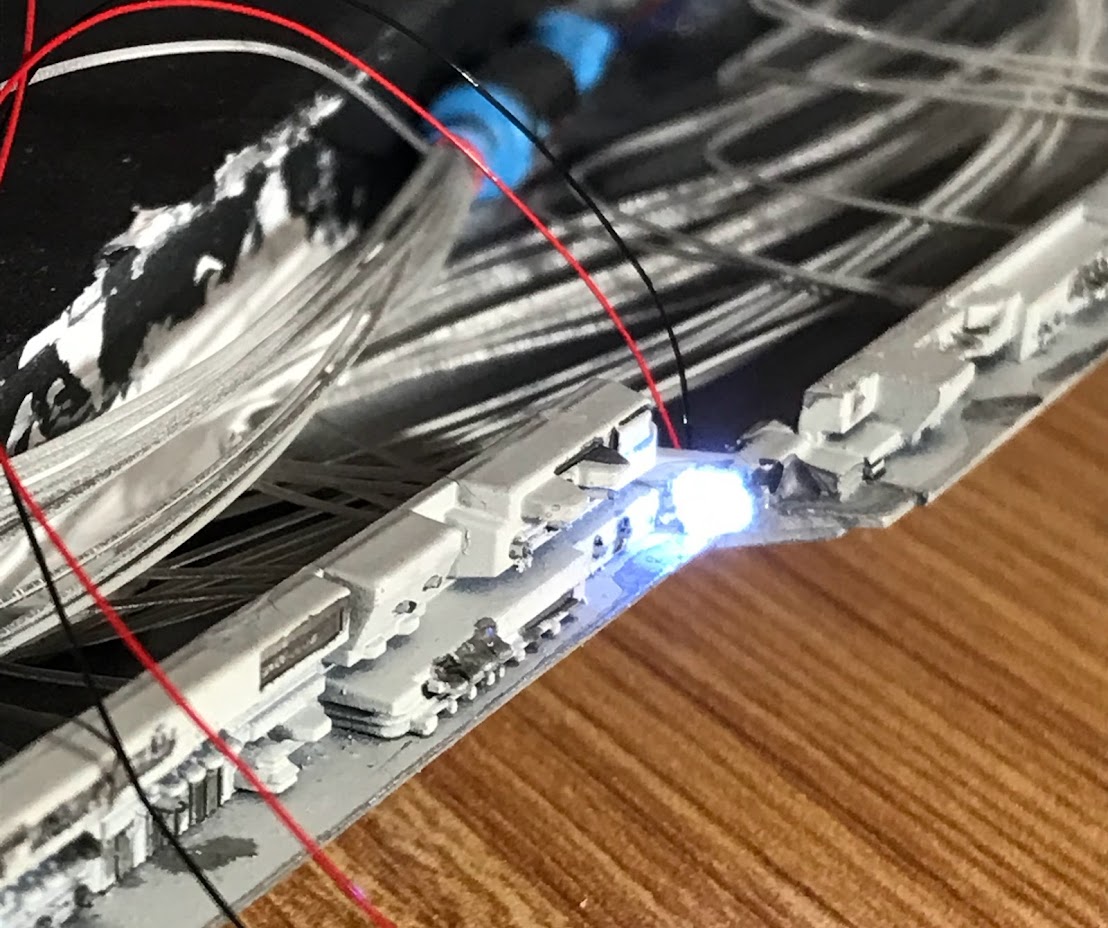
There’s one other little component, there’s a special blue LED that drives 5-6 fiber optic cables in the top front area, that will blink when the Bluetooth control is not paired with the app, and then go solid when a connection is succesfully made.

All the programming is basically done, it’s basically down mounting up the electronics and praying that I solder things correctly. Hopefully a couple more weeks and this thing will finally be done.

Oh wow that’s amazing!!!

I’ve lighted up a few kits years ago with fiber optic cable and bits and bobs from Radio Shack but nothing like this. That’s insane all the cool stuff you’ve got there!

Really looking forward to seeing her all lighted up like the proverbial Christmas tree!!!

Thanks, this is crazy what this has morped into, next time I’ll plan better. Omg the budget for this! Insane…

Bluetooth model in place! The blinking lights mean it’s looking for a connection, it will go solid once it’s properly paired with my app.

Pro mini board now wired in place, with wires for the usb connector to upload code. Those are just temporary and will be removed prior to final mounting.

Left side is the HM-10 bluetooth module mounted in place now.

THAT IS

Can’t wait to see the finished product!

That is sooooooooooo cool!

Batteries in place!!!

So far nothing has burned or melted!

Voltage meter works…

steady at 11.9 volts, basically matches what the multimeter reads.

Custom power on/off switch that I added

Works!

Brains all wired up

From left to right,

  1. The main Arduino pro mini, handles all the lights, bluetooth, and primary audio

  2. primary audio chip, reads from sd card

  3. Secondary Arduino pro mini, handles secondary audio for sound effects during the power on stages, engine sounds, etc.

This gives me multiple layers of sound, overkill, but the actual hardware is pretty cheap.

LED Lights mounted in place on top half

very close to being done, maybe even this weekend…