So recently I purchased a south Dakota class battleship and I would like to scratch build a dry dock to put it in. I have enough materials to create one but I cant seem to find any plans to go off of. Does anyone know where I can find any dry dock plans that could help me build one. [:^)]
You will probably have to scale EarthSat or GoogleEarth images–the dimensions of such facilities being considered “strategic” in the days before satellite imagery was imagined.
The floor width needs to be approximately the beam of the longest ship anticipated to use that dock. The sides are corbled–stairstepped–about 60º from the horizontal. The landward end of the dock can be square, rounded, or with 45º clipped corners. The seaward end gate can be in several styles, from hinged gate, to crane-operated gate to floating gate strategies.
All of which can often be seen used in the same yard. That’s because, once dug, you (almost) never un-dig a dock. You may change the gating, you may change the cranes, but, there’s always a need for just that size of dry dock (and you fill up the lil’ ones before tying up a big-$$$$ one)
Now, as a display idea, you can compress the perspective to need (probably only want to show 3/4 of the thing, and let the case front be the "fourth wall in the scene–that, since the top of the dock with be 15-20% higher than the waterline to account for tides & clearance; this would obscure much of the hull)
Hardest part of that display would be a traveling crane. Which, a person could argue, would distract from the scene–unless you wanted to show a turret of gun being hoisted out.
If you look at page 142 of Iowa Class Battleships by Robert Sumrall you will find an aerial picture of the USS Iowa docked in a floating drydock ABSB 2 at Ulithi Atoll in December 1944. From the size of the ship you can approximate the size of the dock.
Dry Dock with BBs

Thank you all for the information you have provided. I have looked at Google maps at the dry dock in Boston next to the USS Constitution and the book that was mentioned and I have drawn a sketch of the model base. Now I just have to buy the materials ![]() So thanks everyone
So thanks everyone
Do a google image search on “drydock” and see if you can get enough pics to do drawings. I’d guess the size inside would just barely fit a battleship or carrier.
LOOSE CANNONS resin kits may have a 1/700 drydock. could use that as a guide for building a 1/350.
It would depend on the size of the dry dock and size of the ship. The US Navy’s largest dry docks can fit a Nimitz class carrier, although the flight deck extends outwardly over the dry dock walls, but an Iowa class battleship fits with plenty of room to spare. I have worked on the Iowa when she was docked in Norfolk Naval Shipyard’s second largest dry dock, #4, and there was still lots of spare room in the dock.
The USS Iowa in Drydock #4


Dry Dock 8 at NNSY. The largest type the USN has.


The above is what I think of, several docks in differing sizes in a cluster, down at the end of a turning basin. The modern docks are all steeper than what mere memory provided mind’s eye–such are the failings of memory.
Probably worth the Google Image sercch to eyeball Bath, Maine, bath Iron Works, Brooklyn & New York Navy yards; Philedelphia Navy Yard.
Another interesting idea is expressed aboove–one of the small AM shops turns out Floalting Drydock sections. Which would make for an interesting display, of a full-hulled ship, but one “afloat” in the AFD.
One of my memories of when BB-35 had her last major restorarion was going past Galeveston and seeing her full-dry in the FD they were using.
Now, if only my fractured memory would remember if the AFD sections are 1/700 or 1/350 . . .
I agree that the idea expressed above is worth checking out. I realize that this diorama will keep me occupied for some time. m still collecting materials but im going to sketch out the dry dock before making it and buying anything. I will post a picture(s) of the sketch in a few days.
Dry Dock 4 in the picture above is to the left of Dry Dock #s 6, 7, and 3. All four were existent prior to WWII. All but #4 have stepped sides. #4 had stepped sides when I first stared working at NNSY but it went through a semi-disastrous modernization where the sides were recoated with a kind of stucco cement treatment that kept sliding off when the dock was flooded. The old walls had been cracking prior to the treatment. The dimensions are very close to the original, however. Now, if they could just build them like they did in the old days there wouldn’t be any problems. To the left of DD4 is the building way where the USS Alabama and USS Shangri-La were built.
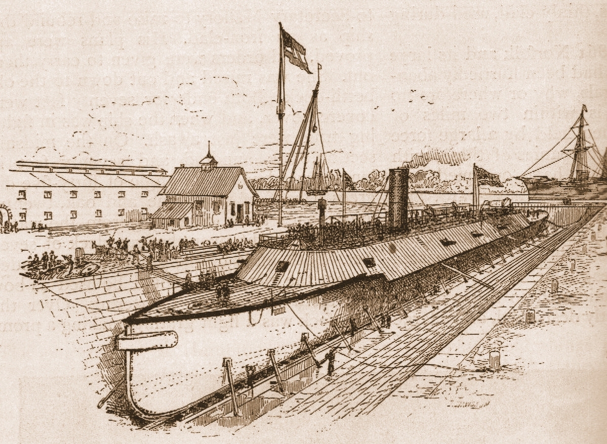
Here is a shot of NNSY’s Dry Dock 1. It is the dock where the USS Merrimac was rebuilt into the CSS Virginia. It is made of granite blocks and was built with pure muscle power. The only modernization it has is the caisson, hand railings and pumps. It is still in use but is limited to smaller vessels.
![]()


so I plan on putting railroad tracks on the base along with cranes. Would the Ho scale railroad tracks work best?
To the best of my knowledge the Bath Iron Works in Bath Maine never had a permanent built in the ground drydock. All their ships were built on sloping shipways and launched by sliding into the river until a recent modernization of the yard. They now build their ships on a level platform and launch them using a floating drydock.
I’m not sure, but I think that the rails (minus the ties) of an N gauge track would be more to scale. And even then might be a bit too large.
Ok I’m hooked! Where can we find drydock history, pics and stuff? Or a new thread so we don’t mess up joshdauner’s build log :). Turning basins and shipyards are fascinating stuff indeed.
freem
Dockyard rails, particularly around a dry dock or on a pier, are recessed. otherwise stuff can’t drive across them. You can easily replicate that with simple plastic strip, set flush in plaster with a slot next to it.
GM is correct. The rails are recessed to be even with the surrounding pavement level, with metal plates covering the mechanisms for throwing the rails.
Might even be best to use itty-bitty Palstruct C channel–even though the prototype would have an “E” sort of section. Which would be about 2.5-3" wide with a ±1.5" rail in the center. That 3" being 0.009" at 1/350 (1/32" channel being about 10" wide to scale.)
American standard rail gauge is 4’-8-1/2" inside to inside, which is 0.16" at 1/350. That’s a shade over 4mm, ZZ scale track, at 4.8mm would be a skosh wide for that, but would look good in the non paved areas for being 1/300 (what a person would do with the left-over Skinkasen could be interesting)
The crane tracks (which are also set flush to the pavement) are about 8’ to 10’ wide, using my potentially faulty memory, and use tracks separate from those used for rail cars. That would be 0.27" or 6.9mm to 1/350 scale.
HO is 1/87 or about 400% too large for 1/350; N is 1/160, about 200% too large (but, not bad for 1/16" = 1’-0" or 1/192 scale if done carefully).
I know I’ve seen a dio of that dock with CSS Virginia being made from USS Merrimack–but, danged if I can remember where. And it was a handy way to gloss over having to guess a bit on the hull form. Since we have a reasonably-good knowledge of the South Dakota’s hull, I still kind of think a sort of half-section of the drydock would still work handily.
Do you mean this drawing?
Or this one?

that would be an interesting thread that i would love to join…