Thanks Real G, I’m in good shape as I have new decals for the old kit, missing when purchased, and yessir they are BRIGHT YELLOW. Watching with interest.
I have noticed the box art of Tamiya kits provide a wealth of detail information that the parts themselves lack. Case in point the side plates on the front spoiler. The kit parts have incorrect ribbing and lacks the kinked lower edge as shown on the box. (By the way, I did some deep diving and got lucky to get ahold of a Model Art magazine that had an exhaustive article on the P34, with painstaking info on the different details found on the cars during their 2-year career.)
https://flic.kr/p/2duXUpL]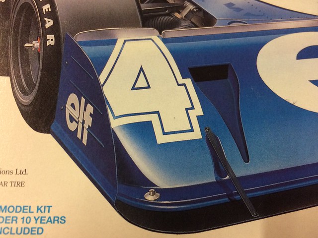 [/url]P34-073 by N.T. Izumi, on Flickr
Sorry about the bad photo, but from L to R, the kit part, the Studio 27 PE part, and the scratchbuilt part.
https://flic.kr/p/uY3UyZ]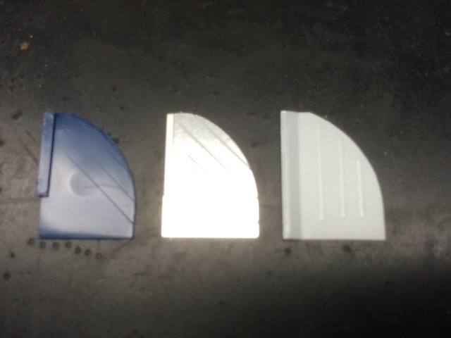 [/url]P34-025 by N.T. Izumi, on Flickr
The embossed ribbing was done using a ball point pen tip on 0.015" styrene sheet backed with a rubber block that came with a beading tool set. A friend had tried this technique to get stamped sheet metal boxes for a scratchbuilt Soviet ICBM carrier, and it worked well so I cribbed it!
https://flic.kr/p/u4Dvdg]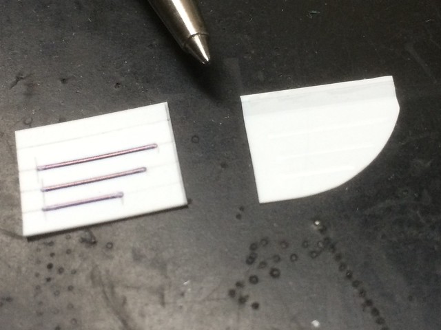 [/url]P34-027 by N.T. Izumi, on Flickr
https://flic.kr/p/u23Ted]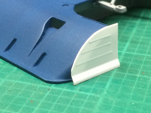 [/url]P34-026 by N.T. Izumi, on Flickr
https://flic.kr/p/voaWgA]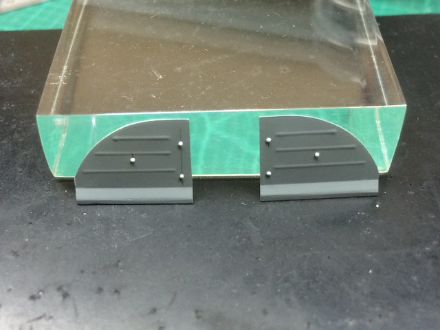 [/url]P34-035 by N.T. Izumi, on Flickr
The kinked lower edge was done by scoring fold lines, bending to shape, then setting it with glue. The beading tool provided punched dome rivets to finish them off. The result is overscale, but at least the pattern is correct.
V E R Y Nice work. [t$t]
Jim [cptn]
Very nice work so far.
I remember building one of those in 1973. I think that it was the 1/12 kit. That was my first big scale kit and I was amaized by the amount of detail. It was so different from the 1/24 scale car kits.
I can only imagine the reaction that model got when it first came out. It is impressive even today. I have been using the instructions of this kit to figure out where all the pipes go on the 1/20 kit. It’s been educational, as I don’t have much automotive experience.
Here is a little workaround - I needed plugs of a certain diameter that weren’t available as plastic rod stock. What to do? I drilled a hole in an old resin pour plug to the correct diameter, then heated a sprue and plunged it into the hole to get what I needed. The ends were squared off and were cut to the needed length.
https://flic.kr/p/s4pgwe] [/url]P34-003 by N.T. Izumi, on Flickr
The plugs I believe are retainers for the fiberglass body shell on the real car. The 1/12 kit has them, but were missed on the smaller 1/20 kit.
Although not on the box top illustration, a standard piece of equipment on F-1 cars is an emergency pull ring which activates the on-board fire extinguisher. To make the pull ring, styrene rod was tightly coiled around a drill bit and plunged into boiling water. I experimented to find the right diameter. A segment was cut out and fitted to a straight piece of rod. Heat stretched styrene tubing (yes, you can do it just like sprue!) was used to make a sleeve.
https://flic.kr/p/wbULwr]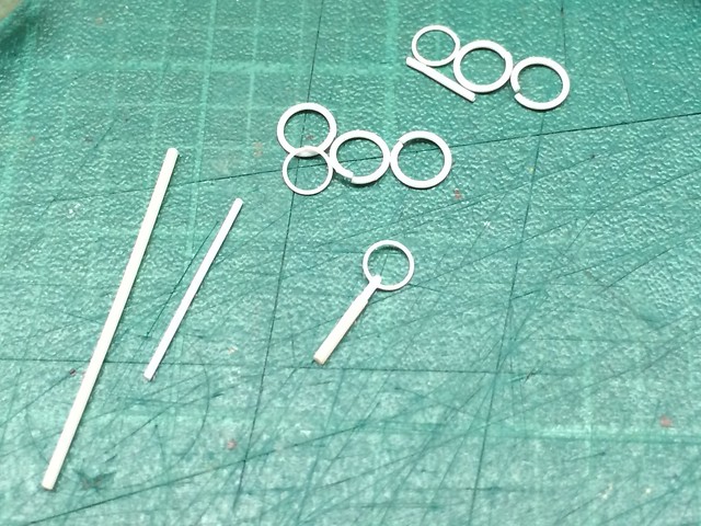 [/url]P34-063 by N.T. Izumi, on Flickr
The real thing was just scabbed onto the roll bar assembly and welded in place, so I notched the roll bar a little and glued the pull ring on. A Bowden cable will be fished to places unkown (probably towards the extinguisher bottle located under the driver’s legs) later on.
https://flic.kr/p/veUe7b]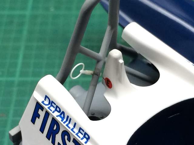 [/url]P34-063 by N.T. Izumi, on Flickr
The ring is ususally painted red, but I cannot see it on Depallier’s car in what photos I have of the 1977 Monaco race. There are other photos from other races where it is silver, so I may go with that.
As can be seen, the photo was taken after painting and decaling had commenced, but I wanted to cover the work in a logical sequence. But note the red “E” decal, indicating the location of the pull ring.
Welcome to the club.
Cool project and what a machine. Watching.
For the 1977 season, team Tyrrell used a rectangular tachometer pasted directly over the existing round faced instruments. Tamiya did not include this bit with their 1977 Monaco release, but neither did Fujimi with their 2nd gen 1977 kits. It was simple enough to make a framed box to represent the tach. The gauge face was drawn up on the computer and test printed on paper. I think if I paste clear tape over it, it will be useable.
https://flic.kr/p/vSTkL8]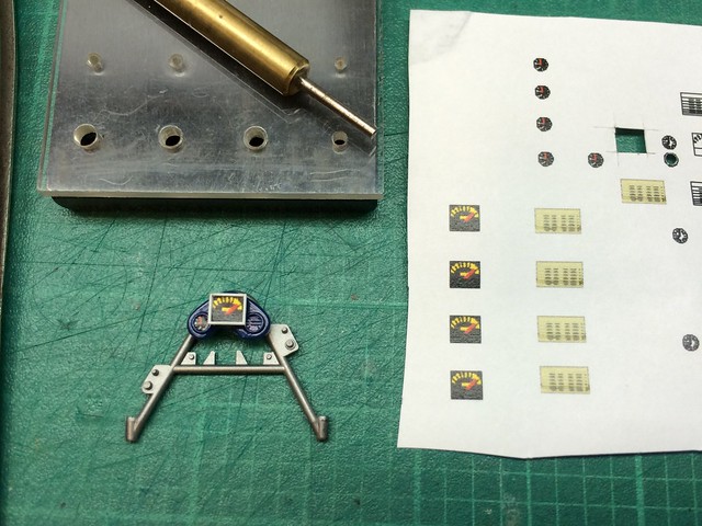 [/url]P34-061 by N.T. Izumi, on Flickr
The yellowish rectangle is supposed to represent some kind of data chart which was attached to the top of the fuel injector box. I also made some round gauge faces with the redline limit, as the kit decals lack this.
The P34 featured rear inboard disc brakes, which means the disc was mounted close to the transmission case rather than the wheel hub. This was done to reduce the unsprung mass of the tire/wheel assembly to improve suspension response. The kit discs are molded integral with the calipers, and lack the slotted edges. Since the brakes will be readily visible after assembly, I wanted to feature the slots. Sooooooo the first impulse was to buy a white metal aftermarket set - which I didn’t like. I ended up making my own from sheet styrene, which ended up looking much better.
https://flic.kr/p/vPLCzC]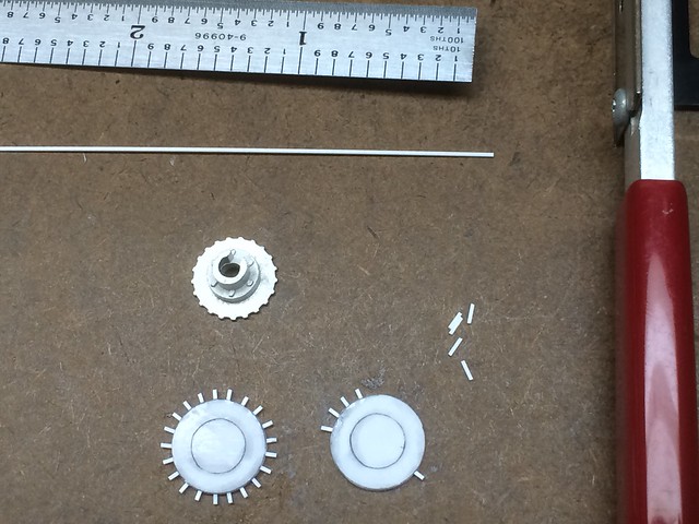 [/url]P34-053 by N.T. Izumi, on Flickr
https://flic.kr/p/vS6gHX]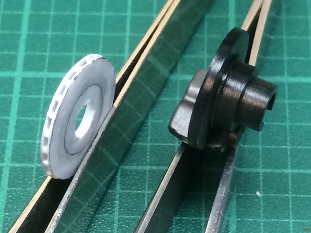 [/url]P34-054 by N.T. Izumi, on Flickr
At first I tried using 0.010" sheet for the disc surfaces, but they proved too fragile for gorilla handling. I switched to 0.015" sheet which yielded more durable discs. I also increased the diameter of the inner insert to increase stiffness. Fine square section strip was used to make the fins. I used the white metal brake insert as a guide to evenly space the strips. The photo was taken before the slotted edges were cleaned up. The kit’s plastic calipers will be salvaged to use with the scratchbuilt discs.
The rear brakes have cooling scoops which are again highly visible, so the solid kit intakes were redone using sheet plastic boxes grafted on to the shortened assemblies.
https://flic.kr/p/vB3t7K]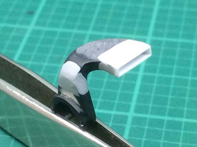 [/url]P34-040 by N.T. Izumi, on Flickr
At first, I tried hollowing out the ends of the kit parts, but that required way too much skill to execute properly. The chop-n-box method was much easier.
You are a person after my own heart (meaning I prefer scratchbuilding more than buying detail parts). Your eye for creating detail added to your modeling skills are really bringing the best out in this kit. GREAT JOB!
[Y][:D][Y]
Ben
Ben,
Wellll… to be honest, I am using mostly scratchbuilt parts because the aftermarket stuff is wrong and/or poor! Not because of any virtue on my part. The upside is that I get more modeling “exercise” trying to solve problems myself.
Here are the new brake discs dry fitted in place. The kit brake assemblies are on the bottom of the photo.
https://flic.kr/p/vV22Zf]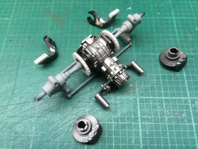 [/url]P34-055 by N.T. Izumi, on Flickr
The kit’s front tires are molded in a different material than the rears, and have some nasty parting lines and sprue attachment points that are impossible to fix. I sourced an aftermarket set of rain tires, which were molded from a material that feels and smells like tire rubber rather than vinyl. They lend some visual interest, plus the car I am building ran with rain tires during qualifications. The PE set I bought had “Goodyear” stencils, which worked well; the real tires had visible overspray so some slop was okay. I’ll add some yellow grease pencil marks later on for added realism; based on photos of the real car, individual tires were numbered according to specific positions, and had the driver’s initials.
https://flic.kr/p/wgdyT7]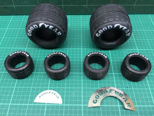 [/url]P34-065 by N.T. Izumi, on Flickr
The front rims were missing some details, which were added using sheet plastic and punched rivets. I got lazy and found some turned metal tire valve stems, so I’ll be adding those as well.
https://flic.kr/p/v1kdbN]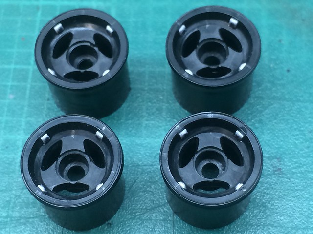 [/url]P34-056 by N.T. Izumi, on Flickr
thats one sharp looking build!!
AAAARRRGGGGHHHH darnit Real G…Valve stems! I keep telling myself to add them but do I? NOOOO, LOL thanks for reminding me yet again. Really itching for my 12 scale. Looking good sir.
Nick, thanks for lookng in!
Armornut, you KNOW you have to do the valve stems now, don’t you? [:P]
I didn’t take any pics of the ugly kit front tires, so this is what you get in the box:
https://flic.kr/p/RhiN24]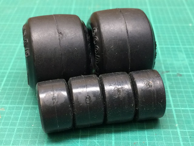 [/url]P34-73 by N.T. Izumi, on Flickr
The small front tires are probably vinyl, not the synthetic rubber that the rear tires are made from, so they are soft, squishy, sticky, and have prominent flaws at the sprue gate attachment points.
The aftermarket tire valve stems are beyond my phone camera’s ability to effectively photograph. I think 1/12 scale ones would be more manageable.
https://flic.kr/p/RhiN9i]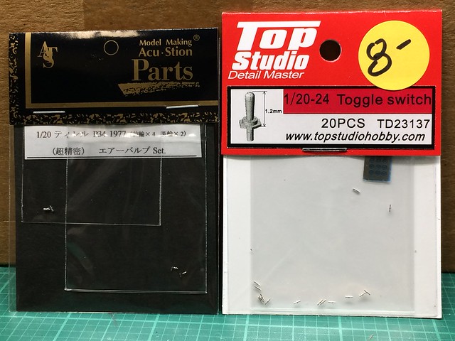 [/url]P34-74 by N.T. Izumi, on Flickr
https://flic.kr/p/2dWKE1d] [/url]P34-75 by N.T. Izumi, on Flickr
The toggle switches are a little bigger.
https://flic.kr/p/2dWKDPm]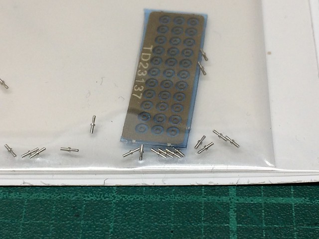 [/url]P34-76 by N.T. Izumi, on Flickr
The only reason I went down the tire stem rabbit hole was that I had read in the IPMS judging guidelines that such details are looked for. And then a dive into the internet yielded such products.
[:D[ [:D[ [:D[
Jim [cptn]


Here is a suggestion for some additional detail on the wheels. How about adding wheel weights? I did that on my large scale Lotus. First I glued a thin piece of plastic to the wheel. Then I put a piece of Bare Metal Foil over the piece of plastic to simulate the duct tape that was used on the real car.
!!! JohnnyK, now look what you did! I have to consult my references to see if wheel weights are visible - if they are, I HAVE to do it! Argh, the mind poisoner has beome the mind poisonee! [:O]

Here is a photo of a 1:1 Lotus type 49. Notice the size of the wheel weight and the silve tape.
Ah yes, and that lovely Ford DFV V8!
Post a couple pics of your Lotus here JohnnyK, I won’t mind at all! There is not enough F1/race car action going on in the forums, and I always like eye candy!
You are doing a great job on detailing your model. As you requested, here are a few pics of my 1/12 scale Lotus 49:


The wiring is different sizes of wire, such as boorbell wire, mouse cable wire, printer cable wire, etc. The bands that hold the ignition wires together are pieces of insulation from a mouse cable. The braided hoses, extruded aluminum compression fittings, and hose clamps are from Detail Master. I removed all of the molded bolt heads and replaced them with stainless steel bolts from Model Motor Cars/Scale Hardware. I don’t remember where I bought the seatbelts, but they are nicely detailed. I bought a black leather purse from Goodwill and used the leather for the seat cushion on the Lotus. The engines on large scale models really sparkle when additional detailing is added. All it takes is time. “There is so much detailing to be done, and so little time to do it”
Keep up the good work on your model.