Help Please…
I’ve scoured the net for a set of aftermarket resin “slats” for an Me-410 and they’re just not out there. I will need to create my own. What I will need to do is remove the original leading edge slat and create a backside for it as you can see in the photo. I’m entertaining the use of Aves Apoxy Sculpt to do this but I must first form the curved shape from the original leading edge. I’ve also thought of using of thin sheet styrene, gently heated, to mould into the curvature of the leading edge. 3D printing is not an option. My neighbor (who has a 3D printer) says he would need the .stl file to do such. Without the file, it would be too complicated to design and there isn’t a file out there.
Why am I doing this? The leading edge slats droop down when there is no aerodynamic force applied to them. So a static display would show the slats deployed.
UPDATE At the advice of a fellow modeler, I will be using styrene strip stock to build up the area and sand accordingly to create the rounded edge of the airfoil. It appears to be the best and easiest way to go about this.
The section labeled 3D print, is the piece I will be creating (actually 2 pieces, one for each wing). That particular one in the photo was a resin aftermarket part from a now defunct company. Photo credit to Chuk
How is this project coming along? That’s kind of what’s keeping me from doing a T39, like my Dad did a lot of flight testing in. Being old-style hydraulics, the slats, flaps and air brake would droop/open when the bird was on the ground.
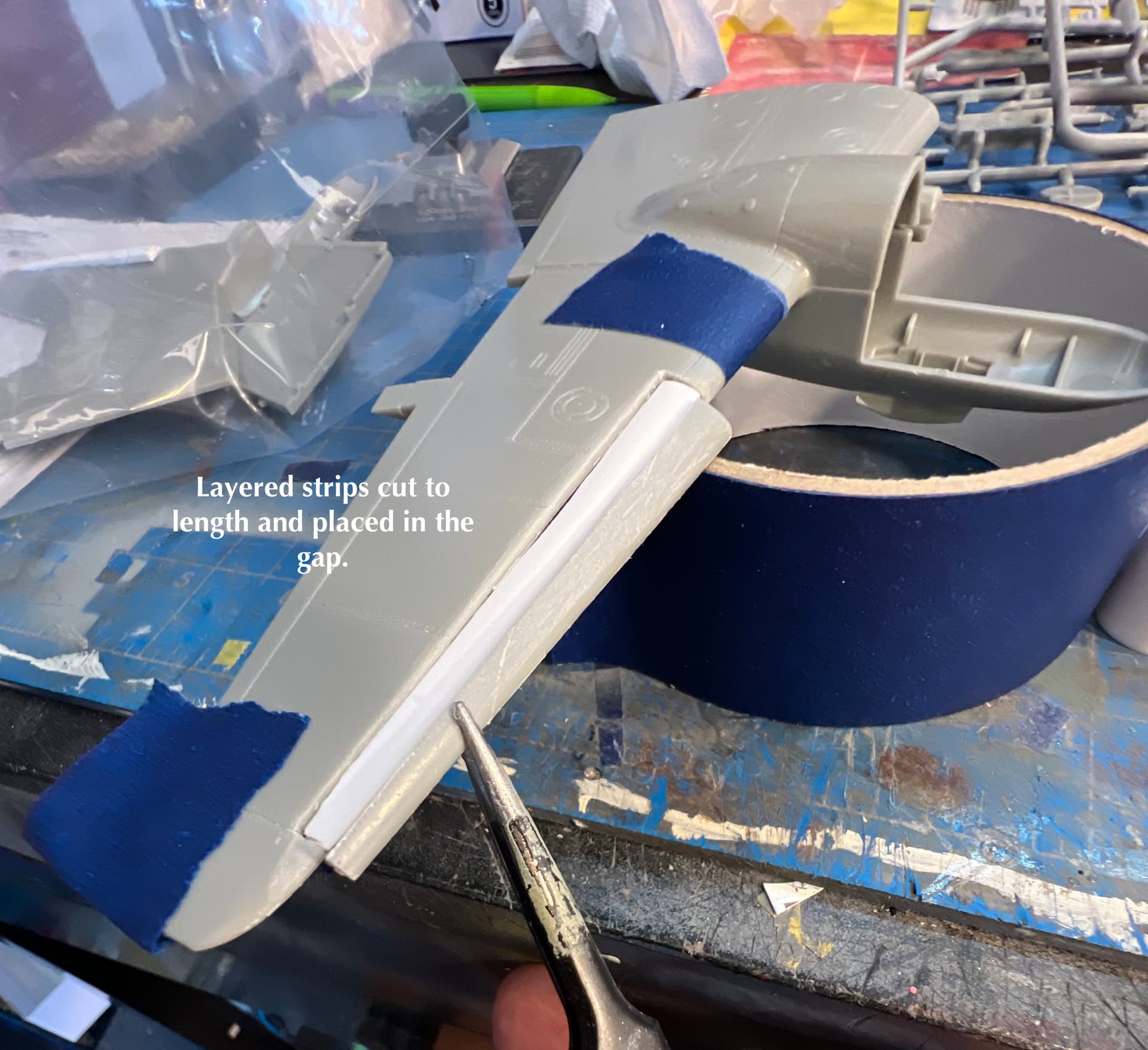
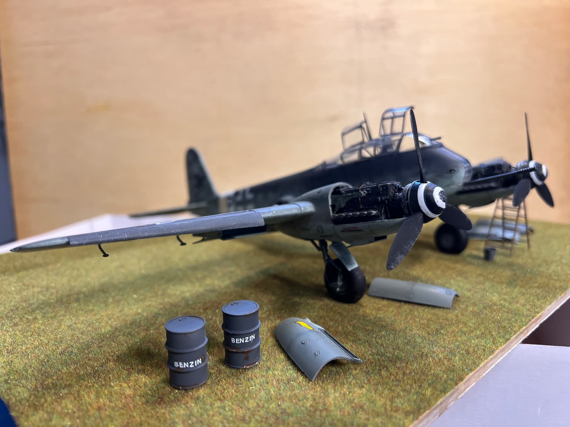
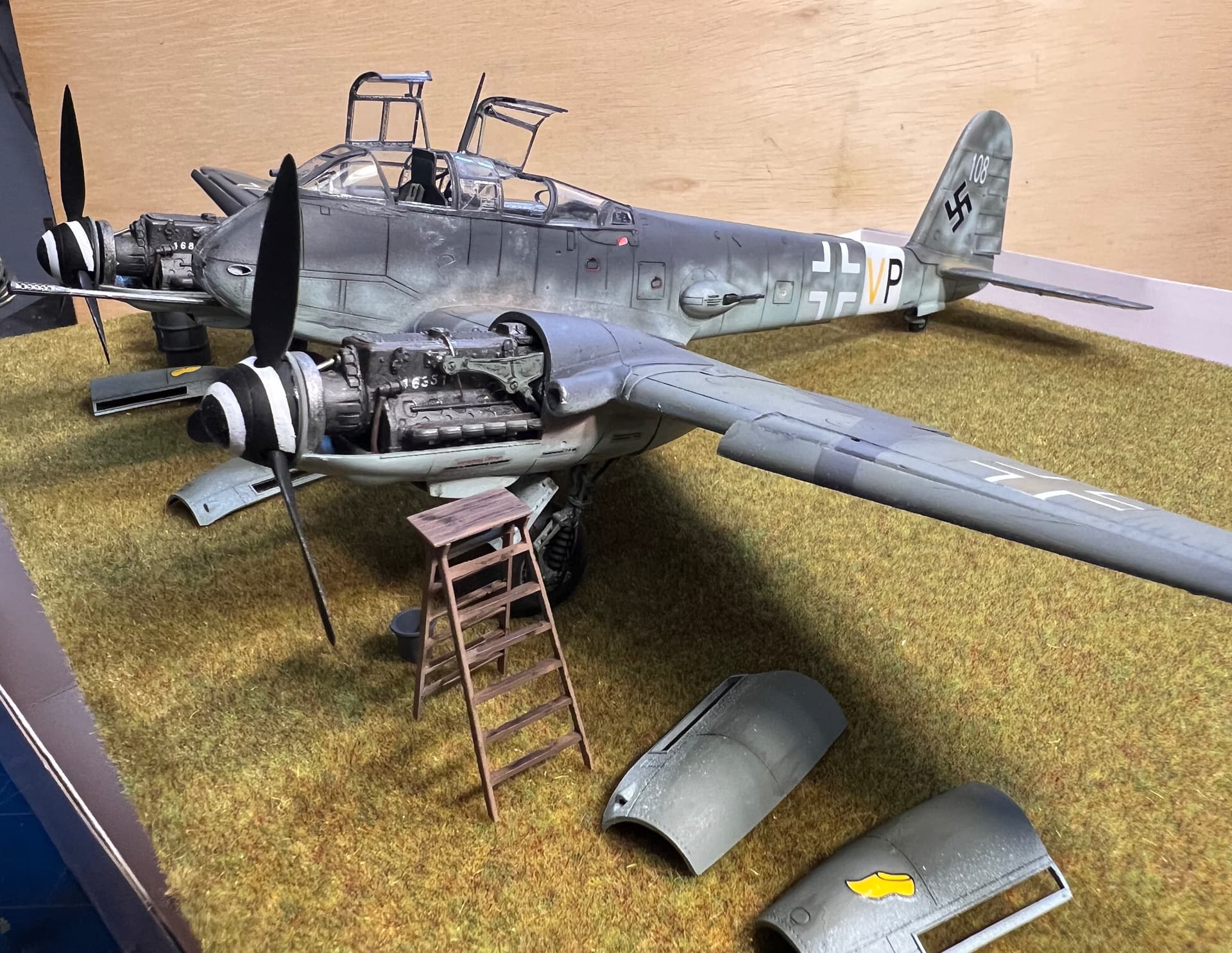
It’s actually finished. I can say it was a bit of an adventure in creativity. First, cut out the top section of the leading edge and saved that piece. That will be your slat. After taping the wing halves together, I used strips of thin styrene, cut to length, and glued them on top of each other. This will be the gap fillet for the leading edge. Cut to length using the top half of the wing where the slat was cut out.
The curvature of the gap fillet must be met. You can do this by taking the upper half and inserting the “cut to length” scratch made section into the void. Then take a fine pencil or maker and trace the curve of the leading edge. This will give you a pretty good guide to go by when sanding this down in the front. I actually used the oscillating sander in my shop because it would stay flat against the sand paper and I could see the curved lines to go by.
Tape the upper wing to the lower wing and insert your fillet. Next you will have to sand down the top of that piece in order to make it slightly lower than the top of the wing. This being when the slat retract, it is flush with the top of the wing. You will also need to make a longitudinal slot in the lower portion of the fillet because of the lower wing front edge. You’ll see what I mean when you set this is piece into the wing. There is a lip in the lower front that must be taken into account.
Next you have to deal with that cut out piece of the leading edge you saved. It is thick and needs to be concave and sanded down from the rear. This is a bit tedious. I used a Dremel with a small grout removal bit to begin gently hollowing the backside of the slat, being very careful in doing such. Finish the concave with a round sanding stick or improvise with 220 paper attached to a rod. Test fit the piece so it comes pretty close looking flush if it were retracted. I was mostly concerned with the appearance of the top of the slat looking as if it would be flush than anything else. When satisfied with the work, THEN glue the wing halves together.
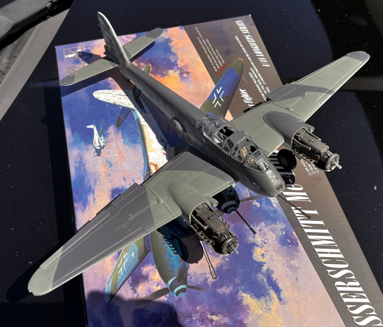
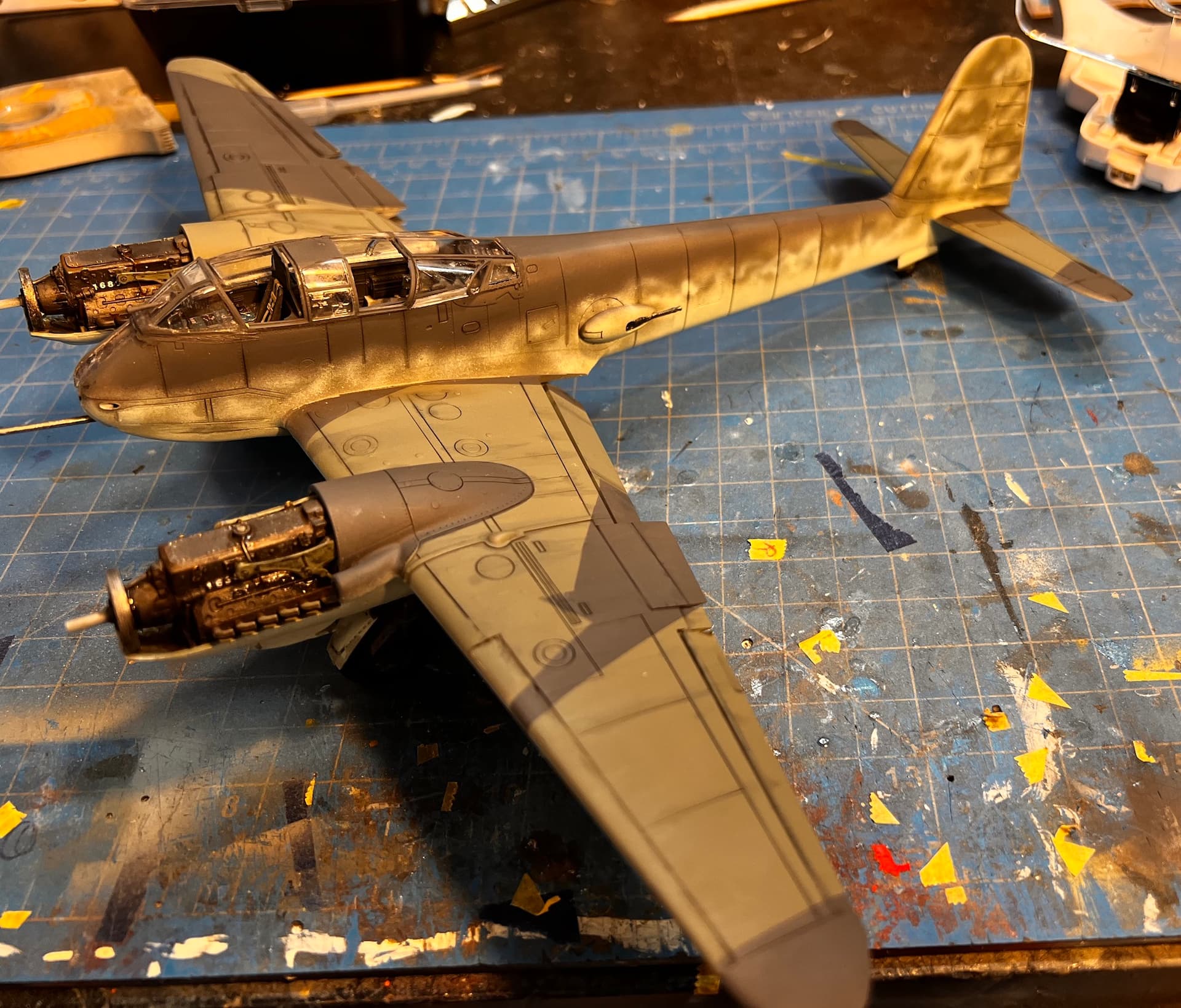
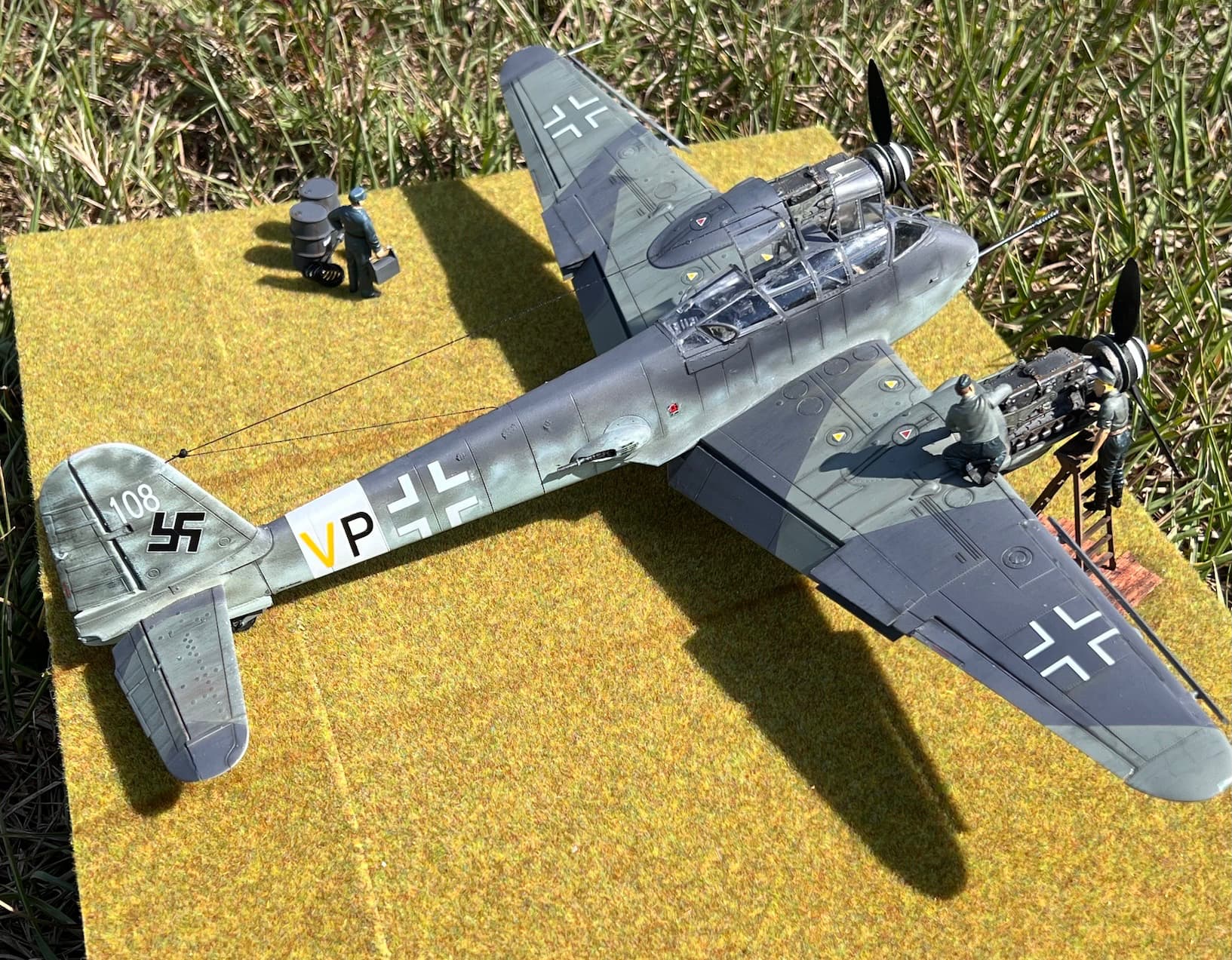
The slat actuator arms were pieces of left over photo etch from a U-Boat build but can be done with scrap styrene. Here are the remaining photos of the results. I hope this helps you with the process, which should work for other models as well.
It’s what I had in styrene stash at the time. Some had suggested round plastic rod but I had troubles shaping that. You could also stack pieces of styrene sheet and cut to size if you don’t have the strips.