really nice john , the detail is incredible ,your also a really neat modeler , it look’s real . steve
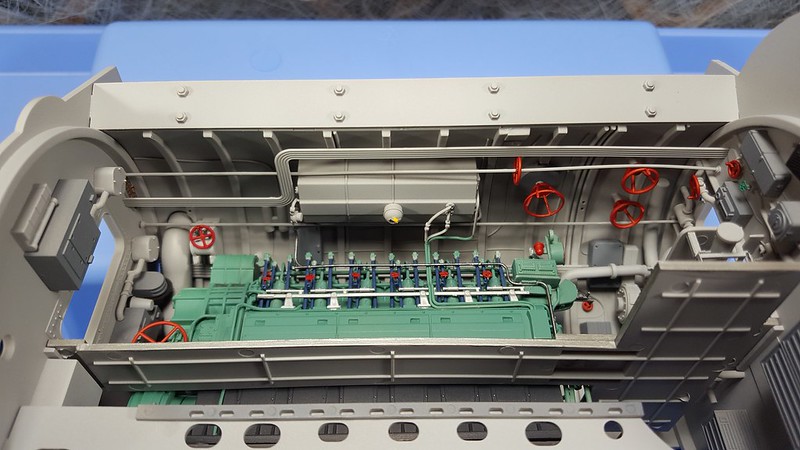
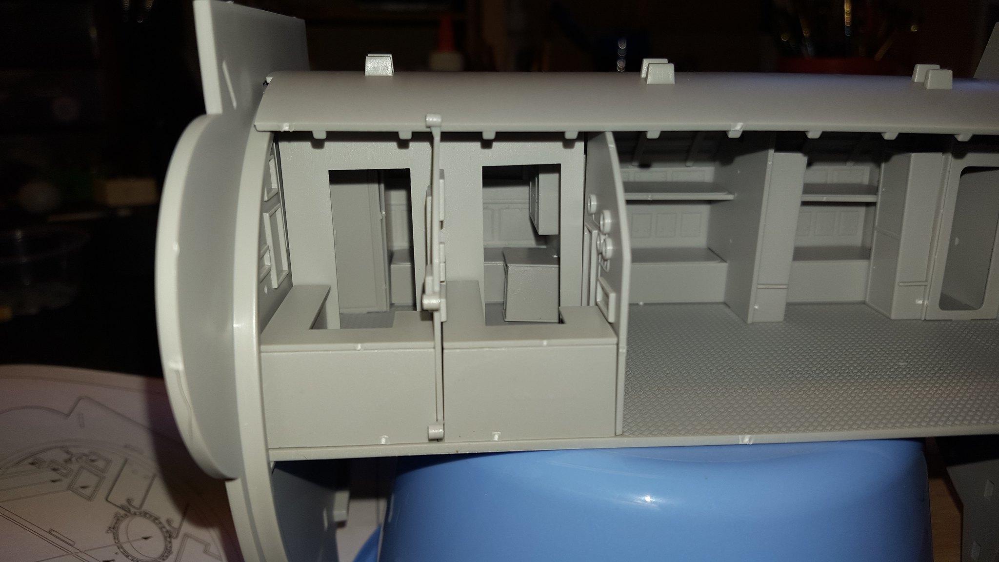
Well, this compartment is just about done. After several dry fitting attempts, I had what I think was the best way to add the last bulkhead to the compartment. I started with the two tabs at the top of the bulkhead and then worked my way down. I was able to use some pretty good size clamps so I went with normal Tamiya thin cement instead of CA. The floor has a good amount of flex possible so it was then easy to put it into the slot on the bulkhead. Lastly the bottom pieces lined up pretty well and some more clamps and after about 30 minutes she was very solid. With the heft of the plastic bulkheads and ribs at the bottom this compartment is very stable. The one long hanging pipe was then glued to the bulkhead. Here is a picture:
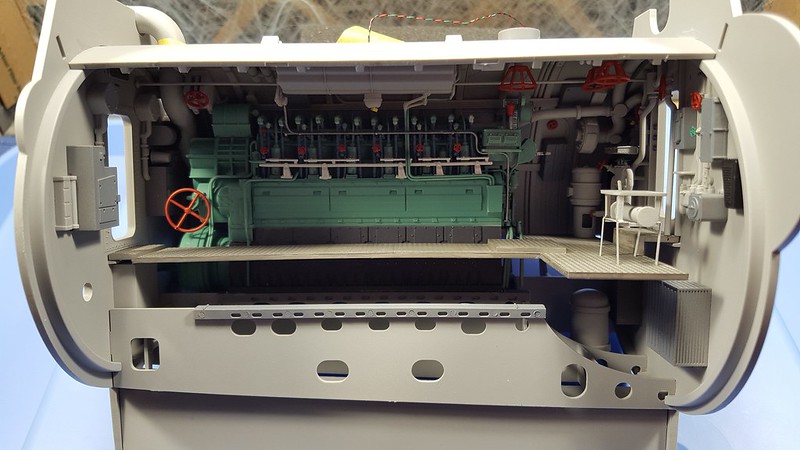
Here is a second picture using a flash to get a little brighter image. I am using my phone for the pictures, so I apologize for the quality as I am not a photographer.
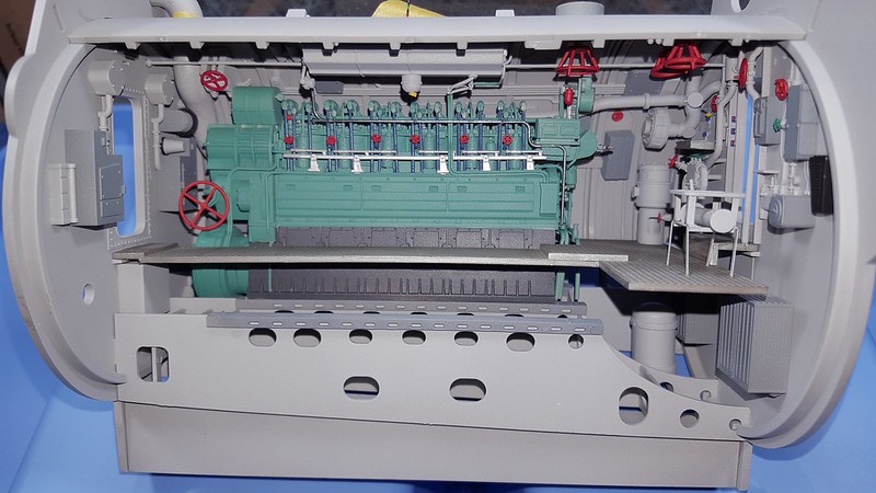
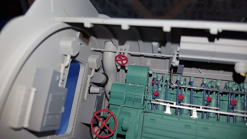
The next step was to get those pipes on the roof piece to mate up with the ones on the engine. I double-checked the instructions and it turns out that there are only two that are supposed to match up. The third seem to just end. Perhaps it was capped and used for some kind of pressure relief? I was really surprised to see how close it was after all my messing around. The one pipe met up almost exactly and the other was only off a bit. I did need to trim a very small piece of length off as they were overlapping. One joint just needed a small drop of regular cement and the other got some CA as there was a bit of a bend to the joint. That was probably more my fault of not getting the proper alignment of the pieces when I glued them separately. The red circles show where the joints are.
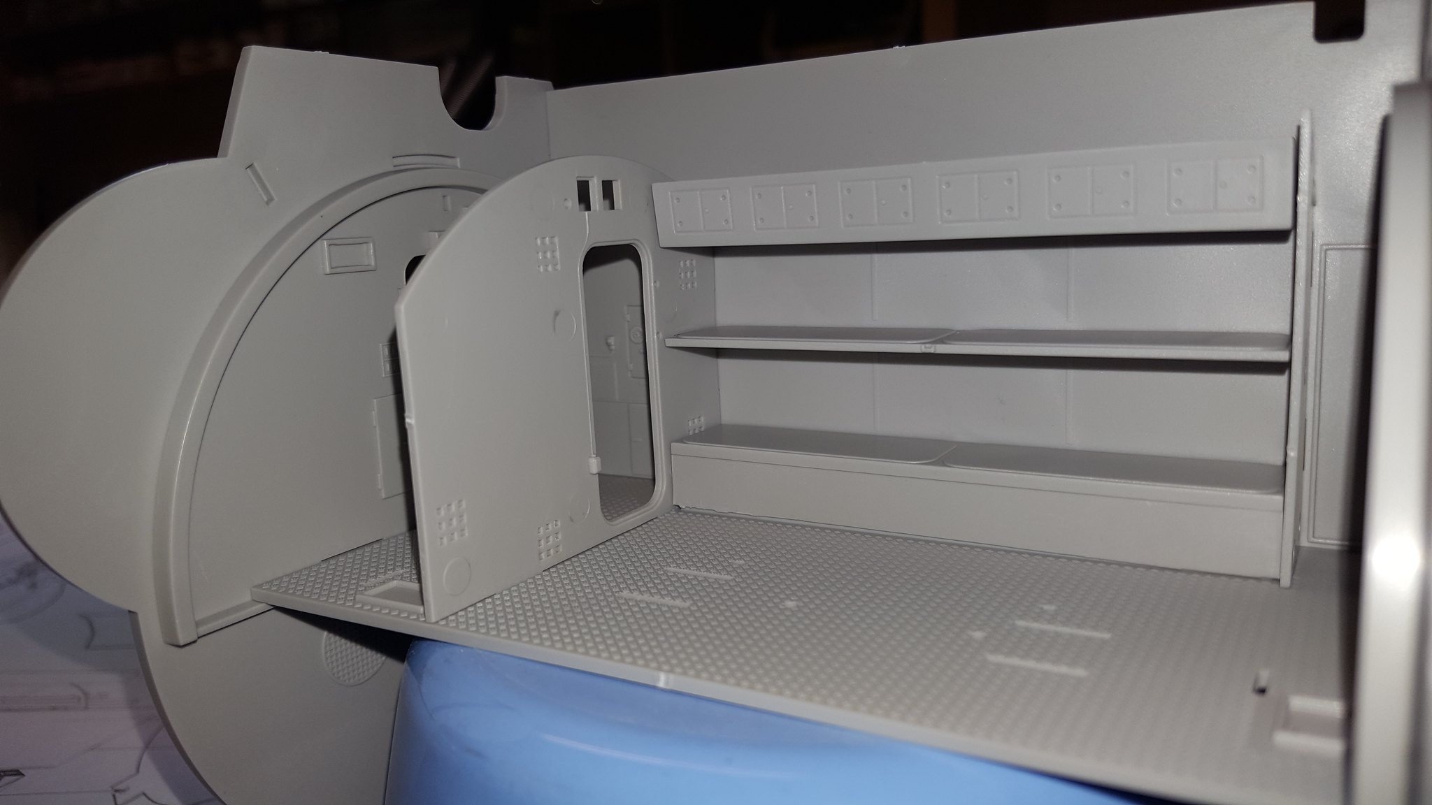
This next picture shows how the exhaust piece a cut comes out of the roof part and lies in the cutout on the top of the bulkhead. It will extend onto the top of the roof of the next compartment and when those two are mated up I will add it in.
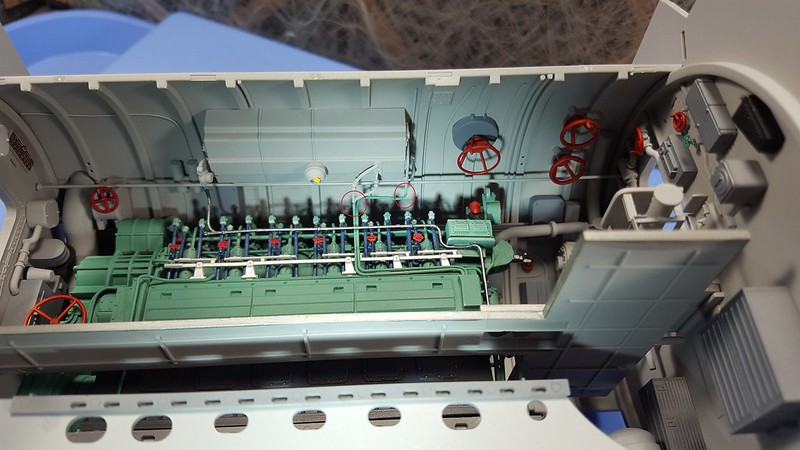
This picture shows the exhaust as it comes down from the roof and bends in and around and mates up behind the engine. I did not glue it at all as I need to be able to make sure it fits at the top, so just some tape for now. You cannot see behind the engine so if it off a bit you will never know. You can also see the join of that long pipe section.
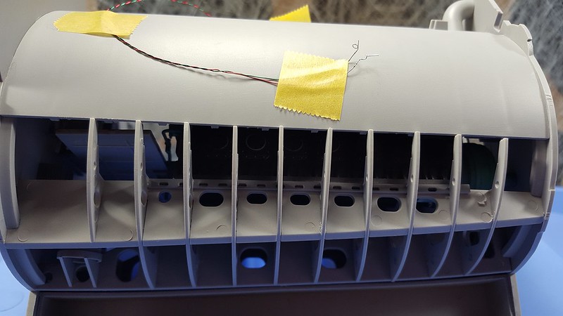
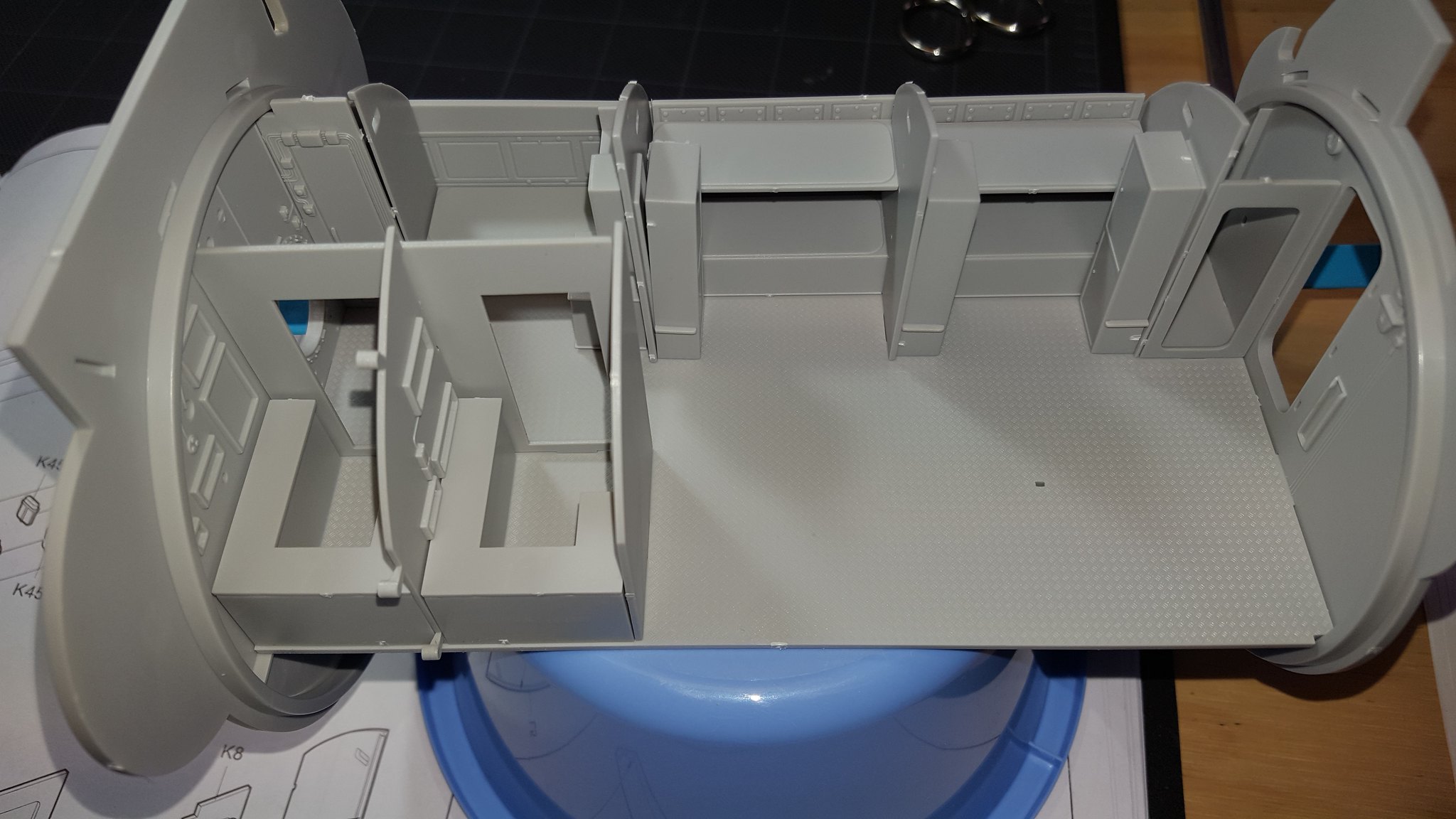
This picture shows how the ribs from the bottom match up to the roof piece. These are not going to be visible at all. It is not a perfect flush fit as the stick out a little behind the curve of the pieces. I don’t know if they will have to be trimmed when I fit it into the hull or if there is some room. Time will tell on that one.
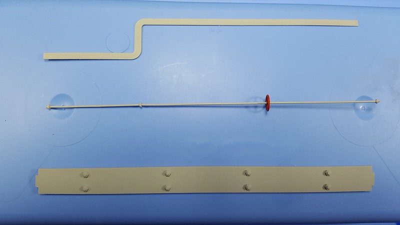
These are the last three long pieces that need to be attached. The instructions say to put these in first before the last bulkhead, but I chose to wait as I had some maintenance to do joining those pipes, replacing the valve wheel I knocked off, and I just wanted to make sure about the LED diodes too.
Here they are after being attached. No issues. The curve in the one pipe going around that one large valve wheel is real not an optical illusion. For all the issues we have read about with some Trumpeter kits, this one so far has been pretty good to work with from the assembly perspective. I have no idea about historical accuracy.
Now for what we all want to see and why I got this one; the lighting. Let me say these were taken in a very dark room with a cell phone, so the image is not a completely true picture of how it looks. Here is the first one:
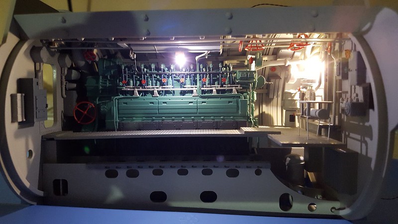
This second one from a slight angle:
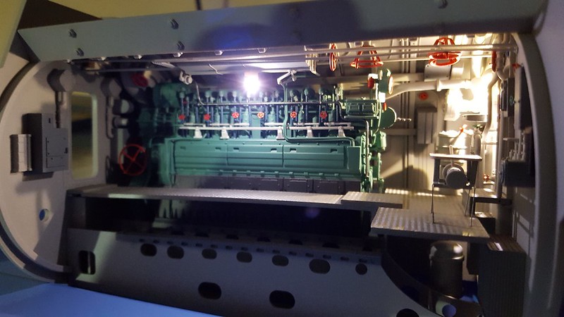
I do believe that the one end is too dark, and I will probably add another LED at that end somewhere. The instructions show only two light fixtures, but I want to make sure it looks more like it actually would have. I have to believe they had enough light in there to see what they were doing…
Well that is all for a bit. I am going to take step back and make sure I don’t get too anxious to rush things. I am not sure what compartment will be next, but I will post it up as I go.
Many thanks for looking and again a thank you for all your comments.
John
All I can say is…WOW!!![:D[[:D[
O-u-t-s-t-a-n-d-i-n-g!!!
Jim [cptn]
Man this makes me want to watch Das Boot for the144th time!
Earlier in your posts I was thinking the interior color should have been slightly darker, but I’m no expert on the subject. You did the right thing going with the light grey, it makes the interior easy to see.
Besides, the Germans were having a hard time mixing batches of the same shade of grey every time… what with the Allies bombing the shipyards all the time.
Sitting on the edge of my seat wating to see more of this…(wipeing drool off my chin!)
BTW/ That engine could stand alone as a work of art all by itself!!!
John !
That is some awesome work .Do they give you both engines in the kit ? Next please ! T.B.
Stupendous!
I think you’re right about the lighting, seems to need a little more by the hatchway.
TB; Thank you very much. No there is only one engine.
john
Thank you. There are a couple of compartments with four lights listed in the roof, so it will be interesting to see if those are too much.
john
Jim;
Thank you.
john
Thank you.
john
Thanks, those folks have some neat stuff for sure. I think I am just going to stick to straight out of the box for the most part. I will add some wires for the deck that seems to be missing and of course my own lighting.
I get claustrophobic just thinking about being in one of those while under depth charge attack. Not for this guy for sure.
john
I hear you there…I went through U-505 in Chicago around 1968, when she was still outside. I was around 5’7" and 135lbs then, and had to turn and twist sideways in some spots.
Can’t even imagine 45 or so men in that sardine tin for 45 days or so, with no a/c like the Gato’s had. Add in on top of that a 75%+ loss rate on crews during the war.
Time to move on the next task. I decided to start from the front of the boat and work aft mainly since there are a lot of pieces that are to be wood and that will take some time and effort. I used a technique I saw at another modeler’s site while building an Albatross DIII and it came out really well, so I want to try it again. I will explain it as I move forward.
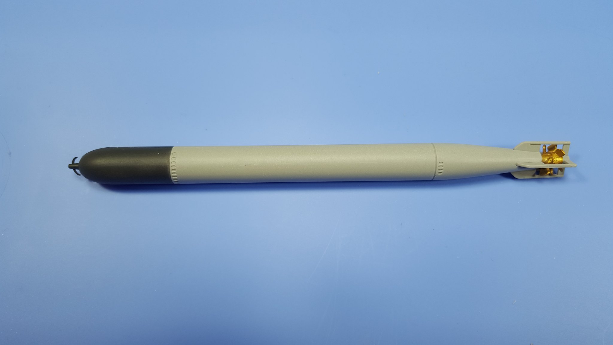
First up from the instructions are the torpedoes. 12 very boring tubes that come in halfs and then get propellers and guards added. Luckily, only four of them will be really visible as far as the seems and assembly goes so I can be a bit sloppy and just get them painted. I am finishing them up, and I started to plan ahead for the wood work so to speak.
The first thing I noticed going through the instructions to pick out all the pieces that need to be done, was they say to paint wood on some ribs of the roof sections… Seems odd that wood would be added to the ribs of the roof. Here is a picture of the roof piece for the front torpedo tube compartment:
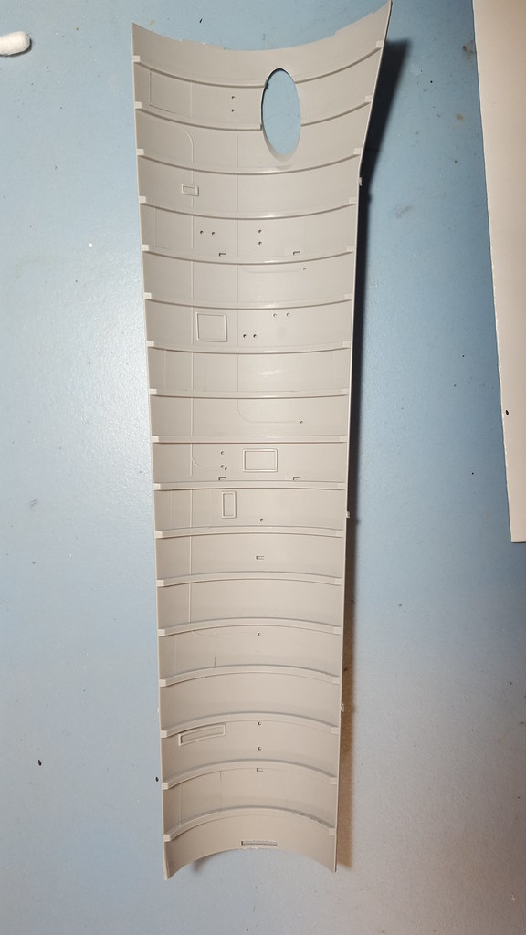
All those ribs are to be painted as wood. I did some hunting around and found the following photos from U-995:
Made me feel as if they are indeed correct. Also looked good for the hemp color on the engine.
Next it is the front soldiers living room. I chuckle every time I see that on the page… Here is a dry-fitted picture without any paint so as to get an idea of what it will look like:
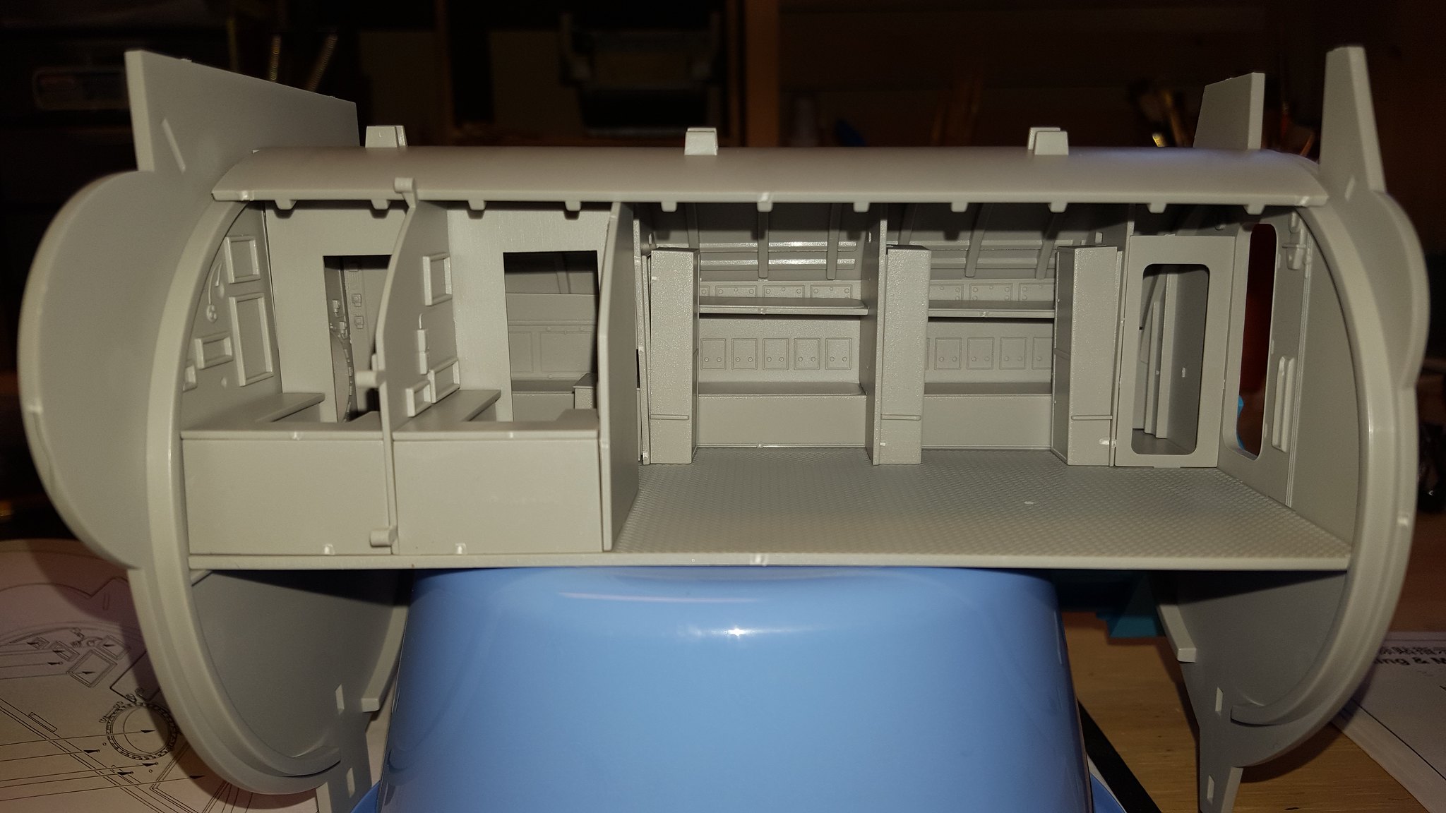
Here is another one showing the front section in a little more detail:
Another without the roof to show more detail:
Nothing terribly complicated in the central control room, so onto the rear soldiers living room. Here is a photo showing the room without a lot in it just to highlight the bunks and the woodwork:
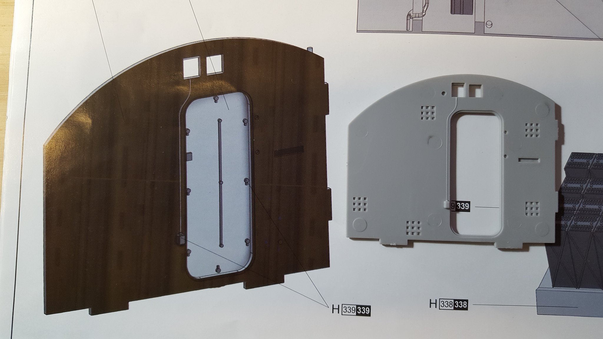
Here is where I came across the first real large issue that needs to be fixed. Both sides of the bulkhead in the center will be visible so I guess I can understand the sink marks, but I am not sure what is up with what I call those “waffle” marks? Here is a picture from the painting guide showing that side of the bulkhead and the piece itself unpainted:
There will be some sanding and filling there to be done. I already finished the engine room and there is nothing wood in the rear torpedo room. Some slats to be painted on the exposed open top deck as well.
That is it for now. Hope to get cracking over the Holiday on the priming and wood painting.
John
The wood was added in several key places to keep the crew from placing bare hands on frezing metal and sticking to it. This was especially true outside during watch. The conning tower was lined with wood.
Hmmm;
I am puzzled about the Waffle marks too . Can’t be for interior venting that can be closed off . Well , shoot . That is a stumper . T.B.
Thanks! That makes sense.
John
I think they are just more severe sink marks as they are on a lot of the bulkheads now that I study them.
john
Well, as I get ready to prime all the parts for the wood effect I realized that the Electromotor and Rear Torpedo compartment has no wood. I decided to finish that up next.
Since this compartment will have two torpedos, I decided to make all of them up. I made 8 with full effect and the rest just with the fronts painted as they will be inside torpedo tubes and not visible. Here is a finished torpedo:
Next, here is a look at the roof looking up from below. It is unfinished with the dials and piping:
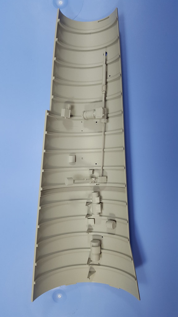
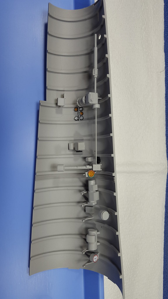
Here it is with the dials painted and added:
Here it is showing the red circles where the four lights will go. I drilled out the holes through the roof:

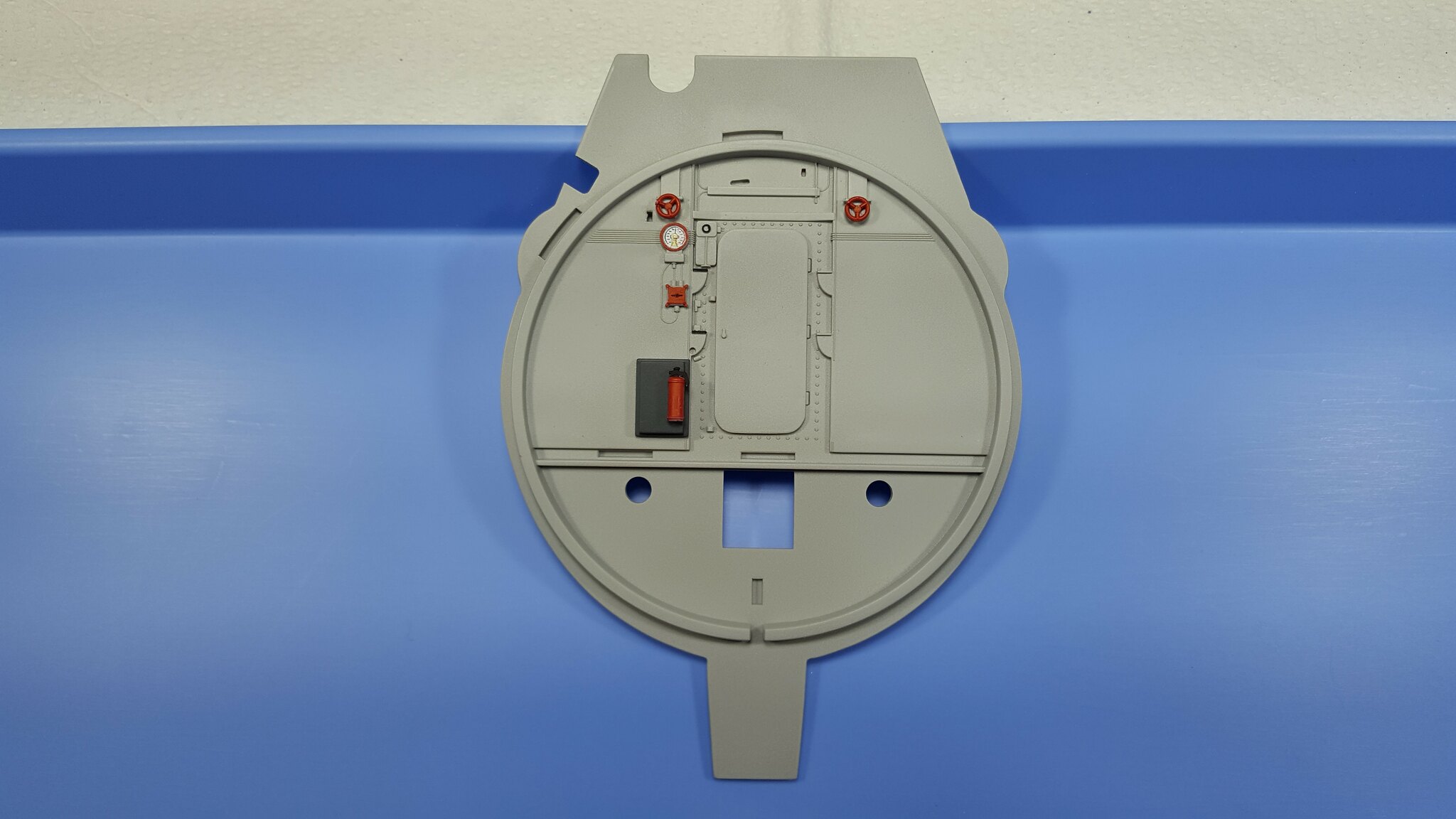
Here is the bulkhead looking from inside the compartment. This bulkhead has a closed door and not a lot of detail:
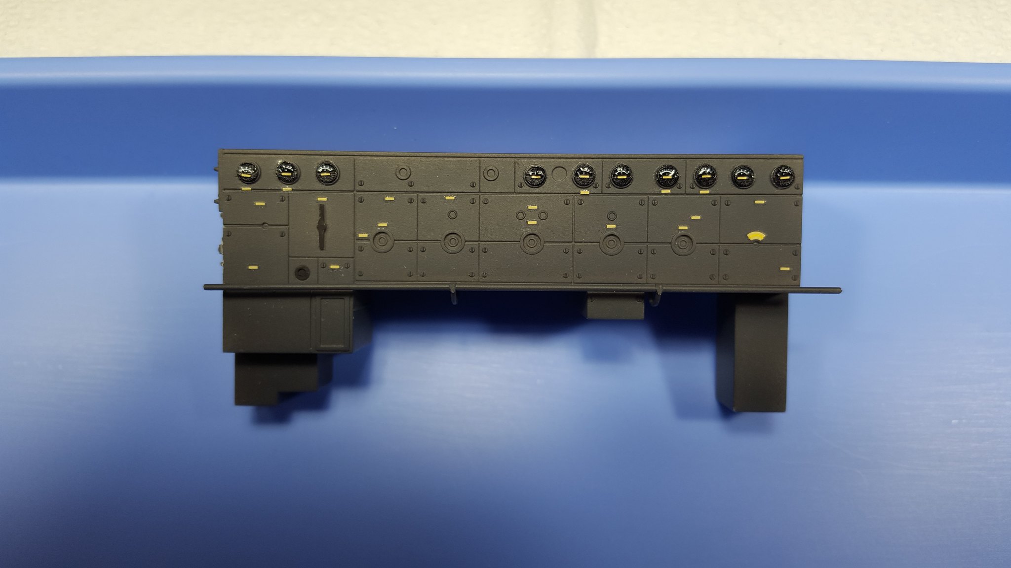
The dial decals needed to be trimmed down so they fit inside the plastic part. Just slid them on and then a coat or two of Walther’s solvent and they settled really nicely.
Now the control “board” for the whole thing. First, here it is just showing all the decals. All the dials and the yellow strips are decals:
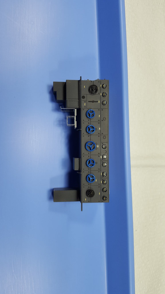
Now adding the valves. The blue looks better when it is inside the compartment and not so lit up. I also broke out the bending tool for that PE “basket”. Much better using the tool. I should have used it on the table in the earlier compartment:
I will get it assembled shortly and then have some more pictures. The other end of this compartment has a very small bulkhead with just one valve and a single hole for the torpedo tube. This compartment is not nearly as busy as the engine room was. There is some overhead plumbing as well to be added in.
John
This looks outstanding John. [Y]
I wouldn’t be so quick to fill the walfle holes in the bulkhead. They look to uniform to be to be sink marks.
Steve