Good day all!
Hope all is good where you all are and that everyone is staying safe from this virus!..2020 has been a terrible year for us all and the sooner it’s all over with… the better! Lets hope and pray for a better 2021!
So on with the next part of this project!..the tail wheel section!..I have been kind of dreading this next part as there is lack of information and photos of this area of the B17. If you look for photos in books or the internet it’s always the same.The whole area is covered with tarpaulin blocking out all the parts you want to see! Enthusiasts go for visits to see the B17 armed with their cameras and they can crawl all over the fuselage snapping away but the tail wheel well area is nearly always out of bounds!
I believe this is because the area is so confined that visitors would have to get on there belly’s to crawl through and for health and safety issues. Well of course this doesn’t help us modellers!
How ever I did managed to find a few photos of said area after hours of searching…(although only seeing certain angles on most of the photos) which meant I had to use my imagination for the areas that I just cant see!..the usual artistic license had to be got out of the draw!
So as you know I am building this fuselage in two halves…top and bottom …so I have started with the bottom half.
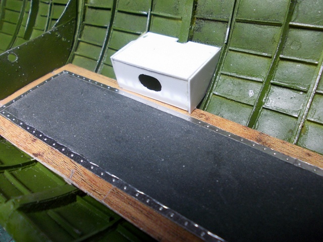
I had to make the tail wheel tub that the wheel retracts to and this was molded from plastic food packaging.
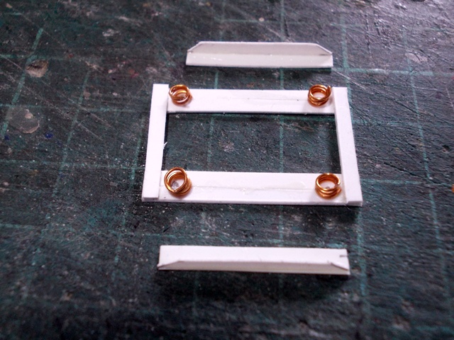
Here is the balsa wood plug that I made…
After heating up the plastic and using the plug (plug and mold procedure) and ended up with this. You can see that I have added some detail with strips of plastic
.jpg)
.jpg)
The wheel well floor was then made from plastic card…
.jpg)
…and from the underside…
.jpg)
The wheel tub was then glued into position…
.jpg)
.jpg)
Now for the wheel.
I hate making wheels!..I find it difficult!..I usually make them out of balsa wood and this time it was no exception!..it’s my own fault as I haven’t invested in a mini lathe…but that is all going to change soon…going to look for one!..meanwhile this wheel was whittled to shape by eye!
.jpg)
.jpg)
.jpg)
Time to paint the wheel tub area…
.jpg)
.jpg)
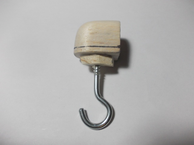
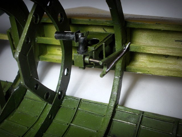
Here is the tail wheel strut…
.jpg)
Here is the tail wheel assembly fork head attached to the wheel…
.jpg)
.jpg)
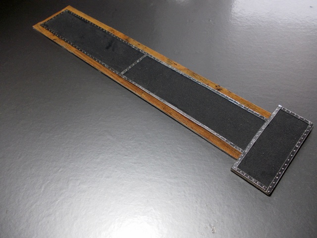
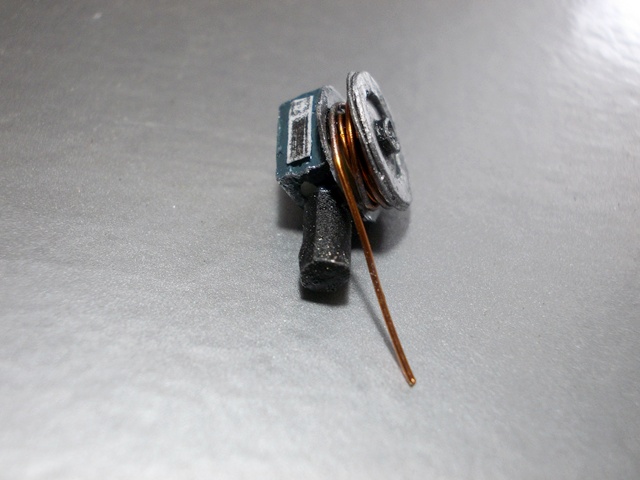
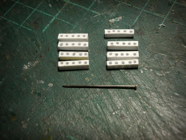
The rest of the frame was then made from metal and electrical cables were added from wire…
.jpg)
.jpg)
Here you can see that I have placed the tail wheel onto the tail frame…
.jpg)
.jpg)
.jpg)
.jpg)
I then glued the painted tail wheel strut onto the frame…
.jpg)
.jpg)
.jpg)
.jpg)
The tail wheel area was in fact covered with a fitted tarpaulin and I thought about leaving it off because it would cover all the detail and at the end of the day this project is all about showing the workings of the B17G …so I then I had an idea of making a cover and having it pulled back so a mechanic could get at it to inspect!
The tarpaulin was made from a painted sheet of tissue paper…the eyelets made from small cuts from a piece of wire insulation and the tie cord was made from thread from the wife’s sewing box and threaded by one of her needles…that took some doing I’ll tell you!..I broke off the Wheel strut in the process and had to re set it!
Here is the cover…
.jpg)
.jpg)
.jpg)
.jpg)
.jpg)
So that is the lower half of the tail wheel area complete.
I have started the upper half of this area and it involves the re tractor motor and gears to bring up the tail wheel…and if I thought that this lower half was difficult I thought wrong!..but we will leave that till the next post!
So until then …Thanks a lot for looking and following this non stop build!
Cheers
Fozzy
.jpg)
.jpg)
.jpg)
.jpg)
.jpg)
_a.jpg)
.jpg)
.jpg)
.jpg)
.jpg)
.jpg)
.jpg)
.jpg)
.jpg)
.jpg)
.jpg)
.jpg)
.jpg)
.jpg)
.jpg)
.jpg)
.jpg)
.jpg)
.jpg)
.jpg)
.jpg)
.jpg)
.jpg)
.jpg)
.jpg)
.jpg)
.jpg)

.jpg)
.jpg)
.jpg)
.jpg)
.jpg)
.jpg)
.jpg)
.jpg)
.jpg)
.jpg)
.jpg)
.jpg)
.jpg)
.jpg)
.jpg)
.jpg)
.jpg)
.jpg)
.jpg)
.jpg)
.jpg)
.jpg)
.jpg)
.jpg)
.jpg)
.jpg)
.jpg)
.jpg)
.jpg)
.jpg)
.jpg)
.jpg)
.jpg)
.jpg)
.jpg)
.jpg)