Tamiya Marder III *Completion PICS p. 10* 03-16-09

Another weekend means another project! This particular project is one that has been waiting quietly for some time in the background and its turn finally came. I will be building Tamiya’s Marder III kit #35248 with a variety of aftermarket goodies including Tristar’s Pz 38t Interior once it arrives…and the fact that it hasn’t arrived yet is going to make the build order for this one a little unorthodox!

Since I’m intending to use elements from both the Verlinden and the Tristar interior set, I can’t start on that until I have both on hand and can see how they will interact with each other. This means that I can’t build up the lower hull tub yet or do anything with the lower hull or suspension for that matter. The only area I can safely work on at the moment is the gun, so I skipped ahead to Step 18 in the instructions and started work there.

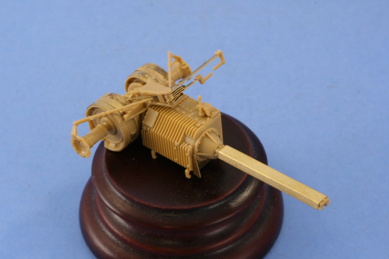
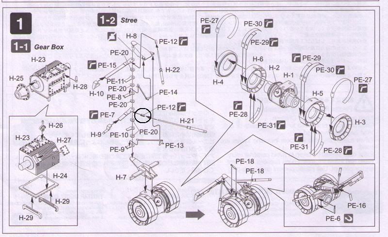
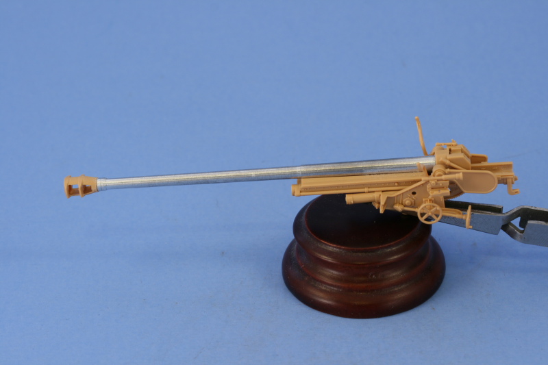
My first order of business was to work with the gun itself. Step 18 directs the assembly of the two-part gun barrel and its attachment to the breech block and recoil tray. Since I was replacing the barrel with the JR aluminum barrel, this step was heavily modified. The breech part already had an opening to take the base of the Tamiya barrel but its diameter was too large vs. the mount pin on the base of the JR barrel. To resolve this, I used some Aves Apoxysculpt two-part putty and packed that into the base. Some CA gel was then used to secure it firmly in place and CA gel used to glue the barrel to the recoil sled.

Another challenge immediately presented itself in the form of the JR white metal muzzle brake being totally inaccurate. Compared to scale drawings in Nuts & Bolts #15 and the kit parts, it proved to be undersized in every way and looks more like a Pak 40 brake than the brake used on the re-chambered Russian 7.62cm Pak 36(r). To resolve this, I went ahead and glued the two halves of the kit supplied barrel together at the front and let it dry, then used a razor saw to remove the brake portion. The brake was carefully trimmed and sanded until it matched to the barrel. Because I needed some working time with the alignment, I used Gator Grip glue instead of CA and set it off to the side to dry overnight.

The other half of Step 18 calls for the assembly of the gun mount and tray. The tray is a two-part assembly and it required some attention in terms of removing some ejector marks that would be visible inside the tray and dealing with the seam down the middle. I used liquid glue and careful sanding to remove most of the seam but a small amount of putty was also needed towards the end to get a smooth finish. The original kit barrel had a rectangular tab that was supposed to fit/lock into the grooves in the front of the tray but I discovered that wasn’t needed so long as you glue down the recoil sled and don’t need the gun to recoil.

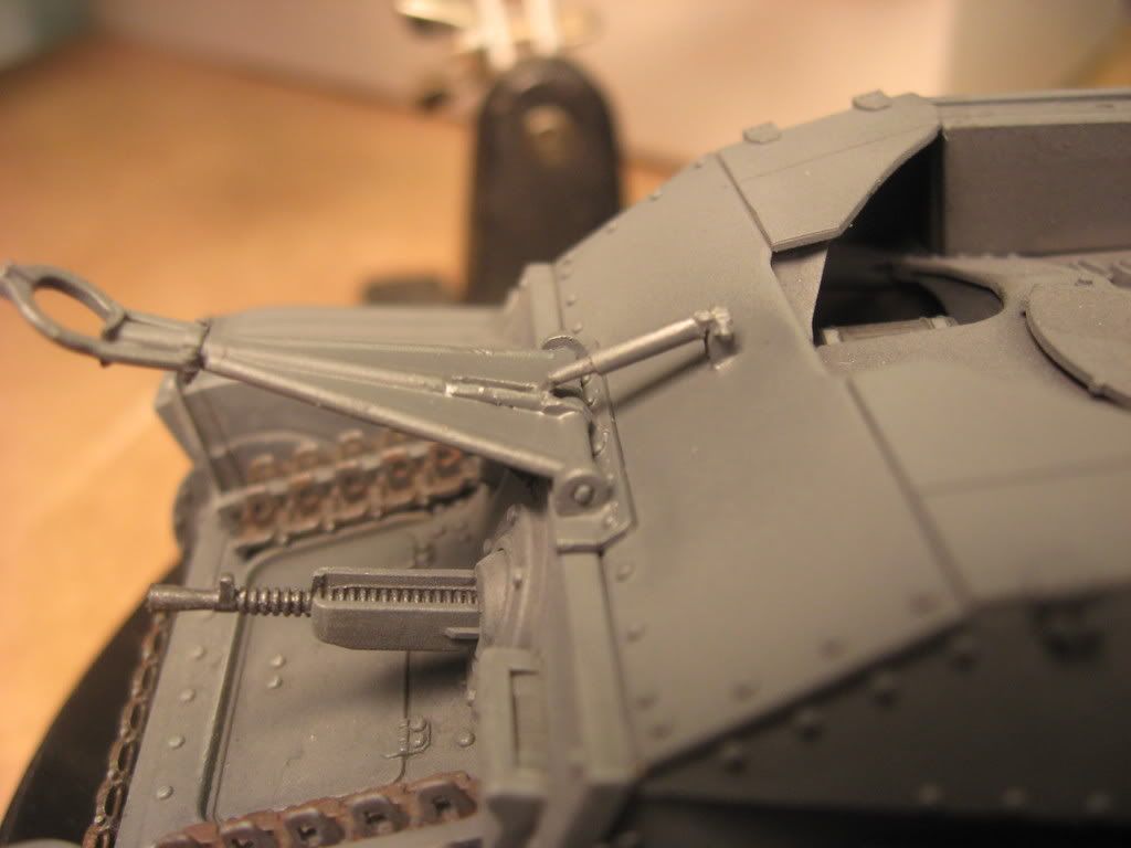
Steps 19 and 20 just demonstrate how to insert and remove the barrel using the locking tab and don’t have any construction associated with it, so it was on to Step 21. This assembles the gun sight and the sides of the gun mount proper. The gun sight was molded solid so I used a pin vise and drill bit to hollow out both the eye piece and the scope end. For the eye piece, I drilled out the hole then used a #11 blade tip and a round needle file to open it up a bit more.

For the sides of the mount, I installed everything except the elevation and traverse hand wheels. These were left separate until the halves were assembled to avoid damaging them in the process.

That assembly is accomplished in Step 22 and the instructions direct you to be careful with the glue to allow the gun tray to elevate once the installation is complete. The right side fits tightly onto a pin and the left side is trapped over a small raised circular point on the gun tray, so it’s very solid.

Step 23 adds some very important details for the equilibrator since these will be visible depending on the elevation of the gun and the way it’s mounted to the vehicle. The fit here is very precise, the elevation gear on the tray appears to make contact with the gear underneath but actually has just enough clearance to elevate on its own without actually making contact.

Before proceeding on, it’s important to note here that the Tamiya instructions contain a very serious error in Step 24 that will cause a lot of grief if you haven’t looked ahead…this step directs the installation and attachment of the front gun shield and the final installation of the barrel and recoil sled isn’t called for until Step 26…however you won’t be able to make this work due to the installation of the sliding splinter shield in Step 24 that’s necessary to complete the front gun shield as it won’t provide sufficient clearance for the muzzle brake to fit through!

As a result, I went ahead and glued the recoil sled down into the proper position on the mount tray with liquid glue.

With disaster averted, I started work on the gun shield. Step 24 deals with only the front portion while Step 25 deals with the sides. In order to facilitate painting and detailing, I’ve decided to leave the gun shield separate from the gun itself but that meant I needed to install some things and test out their fit to be sure everything would in fact align properly. Before getting to that, some shallow ejector marks needed to be sanded down and carefully removed from both the front and sides. There was also one mark on the sliding splinter shield that was too deep and needed some putty work to deal with it. Details from the Eduard set were added for the clasps on the various storage boxes/containers and the holders for the gas masks. The mount pins for the gas masks were carefully removed and sanded down and the holders installed with CA gel to make sure they stay put as they will undergo a lot of handling before it’s all said and done.

The periscopes were added for both the front and side panels and it’s important not to mix these up. Since the front panel sits at an angle, the periscopes also have to be installed at an angle so that they will be straight/vertical once the plate is installed. The Eduard set included parts to replace these mounts but after comparing them to the Nuts & Bolts pics and the way the kit mounts are designed, they weren’t going to be practical or particularly accurate, so they weren’t used.

In order to get the right alignment between the front and side panels, I started with the left side first and used regular glue to attach the side to the front. I followed up with liquid glue around the edges and interior to make sure a solid join was present, then dry-fit it to the gun mount. Everything worked, so the process was repeated with the right side. the right side wanted to bow out slightly, so I used some finger pressure and also added the top canvas support bar to provide an additional contact point to bring it back into alignment. I debated about gluing the shield down onto the supports at this stage but elected to still go ahead with my plans to leave them separate as the working space is pretty tight for hand painting, never mind airbrush work.

I let the shields set up dry-fit so that it would keep its shape and after about an hour or so, removed it. The final element came in Step 26 with the addition of the small semi-circular front plates. These are marked D36 and D35 on their undersides to insure you get them in the right place and I carefully removed those markings with a knife point so they wouldn’t be visible after installation.

While I wait for the Tristar interior to come in I will work on the MK tracks so as not to lose too much time in the process.

Wow… that’s alot!! And off to an awsome looking start. Great work so far!!! [:D]

What’s the price of all that??

I’m starting my first build with aftermarket details in a few months… Got a 1/35 DUKW waiting… Going to order some Verlinden detail set and a Eduard set… [:)]

Watching with interest…

-Huxy

Thanks Huxy! As for the total price…I can only give you a ballpark as much of this stuff I picked up over a long period of time and much of it was on sale.

The kit: $40. MK tracks and replacement sprockets $35, JR barrel $10, Eduard PE $15, Verlinden interior $15 (got it at a club sale), LionMarc MGs (there are 2 in the set but I only need 1, the other will be used on another project) $12, Tristar interior (waiting to receive) $19. So total price tag = ~$150. I should also point out that this by far an exception in terms of project price and scope for me and that this was accumulated over the space of 2-3 years vs. all in one go. [;)]

AM stuff can be expensive and it doesn’t always improve a build, so it depends on the project and what I want to do with it that ultimately will drive what I choose to add if anything. I’m not one of those who believe that you have to add anything and everything AM that’s available for a kit in order for it to be “complete”. Sounds like you’re DUKW project will be a fun one, looking forward to seeing it.

Did you make it to 100 yet??? Well, interior form two kits…this should slow you down…a little.

Off to a great start…Always good too look at all the directions first…you saved yourself!!

Rounds Complete!!

aaahh yes,another convertible.there really is nothing quite like cruisin down the road,the wind in your crew cut ,takin in the scenery.man you just gotta love it.wonderful subject.looking forward to more progress.[8D]

$150? Must admit that I’m too cheap to drop that much on a single kit with all the AM’s. The people that complain of Dragon’s high prices these days, should consider how much you dropped on yours when they start complaining about price.

I have bumped a buck andf a half a few times… not in armor but in aircraft. Pushed it over pretty good once too.[;)]

Lookin’ good Bill. You do like those MK track to don’t you… see you using those a lot.

Mike,

This one’s #94…so have a little bit to go to cross the century mark. It’s on track to happen this year but not until maybe the summer depending on how things shake out. [;)] The Verlinden interior is not as comprehensive as I thought it would be…it’s missing for example the entire radio set and racks. It was only after scrounging around to see if I had anything suitable and coming up empty that I opted for the Tristar interior…it’s a pretty good deal IMHO at $20 since it includes not just the fighting compartment interior but also turret interior details for the 38t gun tank and an engine…so that set will definitely get some use in other kits for the $$. As for the directions, I’ve learned the hard way that when using AM stuff it’s ALWAYS a good idea to study all the different directions before starting in…the Eduard set alone has 5 pages to go with 4 frets of parts. [;)]

Greg that definitely brought a smile! This one certainly qualifies as a convertible all right…especially for the gun crew! [(-D] Thanks for your interest.

Eric, it’s kind of a case of pick-your-poison I think…newer kits arguably don’t need as much “help” vs. their cost depending on the level of detail you want. In this case the rubber band tracks needed to be replaced, the PE is going to address the missing details like the unique straps/clamps and to improve the fenders, the gun is two-part with a seam running the whole length…etc., etc., etc. Could the kit be built without all of this? Absolutely! Every now and then though I like to take an older kit and really go to town on it…and this just happens to be one of them. $150 on a single build project is a very rare thing for me…very rare. [;)] Price is all relative though…and since I was patient and waited, not one of the items I’m using on this kit were purchased at full MSRP but were the results of sales, coupons, and even a local show buy/sell table.

Marc it’s not hard for things to add up quickly, that’s true…and aircraft can do it just as easily as armor depending on what you’re building. [;)] MK tracks are increasingly something that I’m incorporating into my regular build process…I’ve gotten very comfortable with the flexibility they offer in regards to weathering and finishing and, in many cases, they are more accurate/better detailed than even Magic tracks from DML. For this build though they were an absolute must as the Tamiya kit only offers the one-piece rubber-band style in the kit.

Been so busy “saving” my 251 that I overlooked this build, Bill–holy CRAP that’s a wish-list of AM goodies!

I’ll be interested to read what you think really definitely improves this kit from all the stuff you have there. I’d like to do this kit with slightly more than OOB attention, so I’ll be looking in on this one for sure.

Thanks Karl, I think you’ve had the perfect excuse to be distracted a bit! [(-D] I’ll do my best to provide a fair evaluation along the way of what adds the most value in terms of improvements. I’m planning to leave the driver and radio operator hatches open so the addition of an interior is a must, something that the Tamiya kit doesn’t include in any shape or form. I may even leave the top deck removable similar to what you did with your Hetzer but have to see if that’s going to be practical.

Ah memories. I built this kit about a year ago Bill and it’s a really nice kit. I’m looking forward to see how yours turns out especially with all the extra goodies.

Not sure if its included with some of the after market stuff that you have but the one thing that’s missing, aside from tool clamps, is part of the travel lock. I do believe its there to lock the TL in the up or down position. I have seen this in just about every pic of this particular Marder and was surprised that Tamiya did not include it. Here’s a pic of the one I scratched for mine.

Something tells me that you already new about this but just in case[;)]

Wow, Bill. Quite the all star lineup, I’ll be interested to see your progress on this one, many of those items are new to me, but lie close on the horizon.

Nice pictures and log, as usual.

Like the Police say, I’ll be watching you on this one.

Bill

Steve, thanks for the heads-up and the pic of your fix. I knew it was missing and it’s not addressed in any of the AM sets because it’s a 3-d object but I have the same plan in terms of scratching a suitable stand-in. It is a curious omission given the placement and its prominence but not that complex of a part really. [tup]

Bill, considering that song by the Police is consdered to be a “stalker” song, I’ll take that as a compliment! [:D] Glad you’re along for the ride.

Looking forward to watching this one.

Thanks Matt! [;)]

I was very fortunate in that the Tristar interior set that I’d ordered came in on Friday, just in time for some weekend building! The set is a pretty impressive one with over 140 styrene and over 70 PE parts, so plenty to keep you busy!

Before I dug into that though, I needed to decide what elements from the Verlinden set to use. These were then given a good soaking in soapy water to remove their mold-release agent and set off to the side to dry. Initially I determined that I would use only the front superstructure plate, the side panels for the lower hull, the Pak 40 ammo bins, and the rear bulkhead. I ultimately would decide not to use the Verlinden bulkhead but more on that in a separate update. Because the Verlinden interior is designed for both the Marder III and Pz 38t vehicles, the right side panel had a fire extinguisher molded in that had to be removed to allow the Marder ammo bins to fit on that side. I removed it carefully with both sprue cutters and knife trimming, then sanded it down. The openings for the hull MG and the radio operator’s view port had some small film that needed to be removed with a knife point as did the armored air vent on the radio operator’s hull side. Casting blocks were removed using a razor saw and then carefully trimmed down with a #11 blade and carefully sanded.

While the parts were drying, I went to work on the 1st step in the Tristar interior instructions and it’s quite a busy step. A pic is worth 1000 words, so here’s the step diagram to give you an idea.

The strips for the brake drums required annealing in order to get them to fit properly, I accomplished this by carefully heating the parts in my kitchen gas burner with locking tweezers…just a second or two in the flame is all that was needed. They were then glued into place one end at a time with CA gel then wrapped and secured with the other end. The steering lever assembly was an exercise in patience…essentially all the parts stack on top of each other but you have to do it upside down as the pin that holds them is on the top piece vs. the bottom…why they designed it that way I don’t know. The pin isn’t quite long enough to hold all the pieces either, so the last 3 you have to fit by eye to keep everything lined up properly. I assembled all the levers first and then added the little connecting arms as trying to do that first is nearly impossible as they are very very delicate (and tiny!).

The lower hull is assembled as a series of panels, so in order to be sure that everything would play nice together, I went ahead and installed the Verlinden panels to the Tamiya hull sides. The Tamiya panels had an angular molded in bar that had to be completely removed to allow the panels to fit on both sides. The Verlinden pieces fit almost exactly to the Tamiya parts with just a little bit off on the lower edge on one piece. Both panels were glued in place with CA gel. Initial test fits with the hull floor and the Tristar elements showed that I needed to trim down some of the molded on detail above the side pad for the driver to allow proper clearance for the steering levers when they were installed. From this point on everything requires LOTS of test-fits, test-fits, and more test-fits to avoid problems as tolerances are very tight all around.

With that taken care of, the next part of the step was to assemble the transmission and its stand. These parts went together very smoothly and is ultimately why I decided to go with the Tristar bulkhead instead of the resin Verlinden bulkhead. The Verlinden bulkhead is very thick and the included drive shaft is too short, so the Tristar parts will be used instead. The drive shaft was installed to the transmission and the transmission added to the brake housings. The PE leather cover was also added as it will be the foundation on which the radio rack is installed when the time comes and I needed everything solid here for fitting purposes.

Next were the details for the hull floor itself. The driver’s gas and brake pedals were added without any real modifications required for them to fit. The cross bar that the transmission mounts too as well as the seats from the Tristar set had to be trimmed to allow for clearance of the Verlinden panels and the molded on bar in the Tamiya kit carefully removed and sanded down since it was in the wrong place by about 2mm. The ejector marks in the floor was filled with Squadron White putty and sanded smooth. After careful test fitting with the Tristar bulkhead and the side panels, the PE insert representing the wooden floor covering was installed using liquid glue which was carefully flooded over the PE plate so that it would take advantage of the large surface area but not mar the PE details appearance in the process. The crew seats from the Tristar set were assembled, these are highly detailed items with the ratchet mechanisms for the seat adjustment represented with multiple PE parts and separate top and bottom seat cushions. I left the cushions separate for now to facilitate painting but the seats themselves were installed. Their placement had to be precise, so a lot of test fitting with the transmission/brakes and side panels was called for.

The transmission and brake housings are just dry fit for now. I still need to work on the radio racks and the transformers before this area is done. The bulkhead also needs some detail work before it’s ready to go, so next weekend will see continued emphasis on the interior and possibly some painting!

Wow!! Simply stunning!! I guess that step 1 is easier once you get started with it?

And one question, you think the Tristar set was worth the money? [:)]

It still looks stunning tho’!! Oh wait, is that tank right side steered???

WOW, Bill; that’s some intricate work there! You’re handling it perfectly, as we’ve come to expect!

The question is, will you be able to see any of it?

Nice Bill, I was wondering if you could do me a favor? I have the same interior set on my tristar flakpanzer, and It greatly confuses me, I was wondering if you could take a close up shot of the gearbox drum assembly for me? especially how the connecting arms are attached to the drums, what I dont understand is piece PE-12 that connects to H-21, is this piece supposed to be rounded around the end of H-12? Borrowing your scan I have circle the parts I am most confused about. I’m assuming nothing in the entire assembly moves correct? Thanks bill.

I hope the answer to doog’s question is yes. It would be a shame to cover all that nice detail.