Hello everyone. It’s a been a while again. I started fooling around with one of my next builds on the list and with all this disruption to my normal busy work schedule I figured I might just be able to squeeze a WIP out of it. I plan to do this post in the same manner as my others where I’ll show some easy ways to kick up the detail a few notches and improve on different features of the kit so that we have a nicer looking aircraft. Much of this is within all skillset’s reach. It just takes an eye to realize it and a will to do it. Some things will require some better tools. I was hardheaded about a lot of scratchbuilding years ago and tried to do more with less which can help make you savy, but ultimately save yourself some grief at some point down the road and pick up a set of whatever it is you need. It can go a long way to a more consistent and much nicer build.
So here goes…
The Kit
 s-l1000 by Britt Vallot, on Flickr
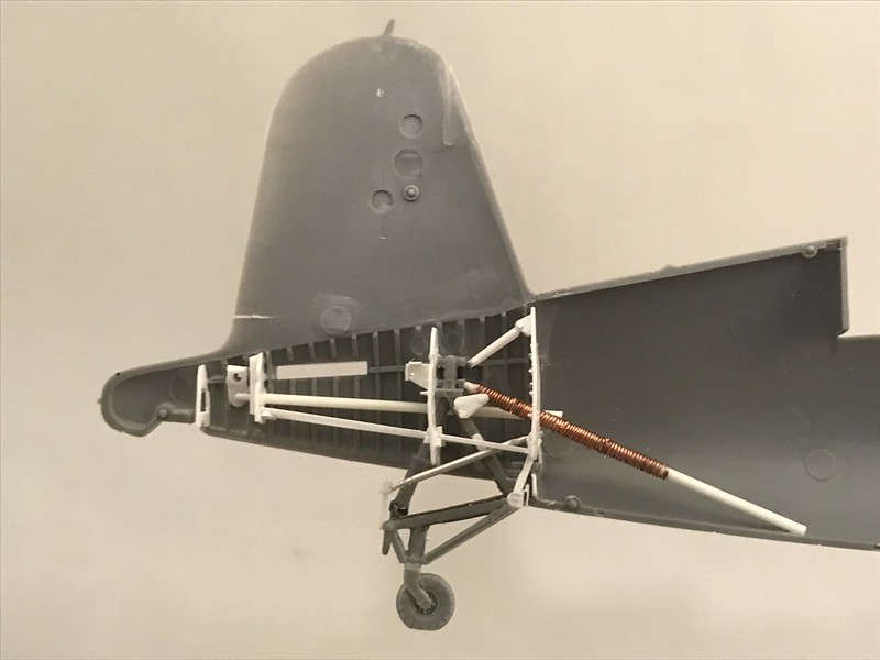
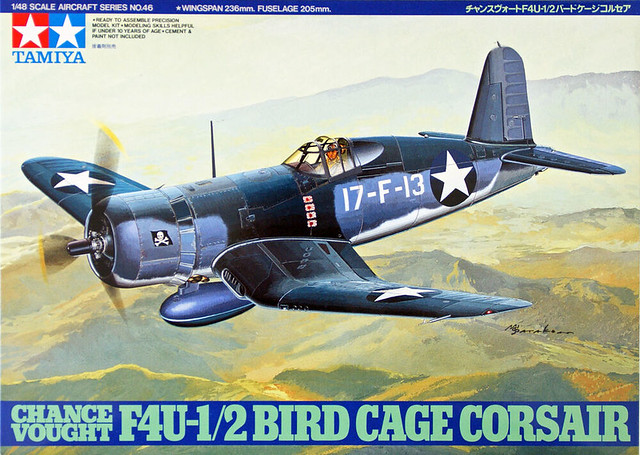
Tamiya’s 1:48 Birdcage Corsair. By all measures it’s a very solid kit. It’s quite accurate and well-engineered with a few tricky spots to navigate. Very fun to build and there’s plenty of after market goodies out there to display your build in a variety of means.
The Man
Kenneth Walsh
 Untitled by Britt Vallot, on Flickr
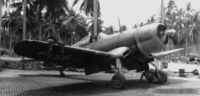
There’s much to be said about Walsh. He was actually the first Marine ace in the Corsair in the PTO. By late 1942, Corsairs were being delivered to the Pacific where they were sorely needed to help with escort missions around the many island chains. Wildcats didn’t possess the fuel capability needed for long escort missions and it was the Corsair and Lightning that filled the gap until later variants of the Mustang would arrive late in the war. Practically day 1, Walsh and the marines of VMF-124 were thrust into the thick of it. They were quick learners and eager to lay out tactics for the Corsair against the Japanese air superiority. His Medal of Honor flight was on August 30, 1943 where Walsh was in a huge aerial battle against 50 Japanese aircraft. Walsh took down 4 himself before eventually having to ditch his aircraft. He was originally assigned as an escort for B-24s when he began having engine trouble which caused him to set down at a nearby base and grab an immediate replacement. While trying to catch up to his group he came across a handful of Zeros attacking B-24s and dropped two of the Zeros while by himself. After continuing on, he hears a radio distress call where Zeros were attacking another part of the B-24s and Walsh engages and takes two more Zeros down. Walsh ended the war with 21 totals kills.
 Untitled by Britt Vallot, on Flickr
The Engine
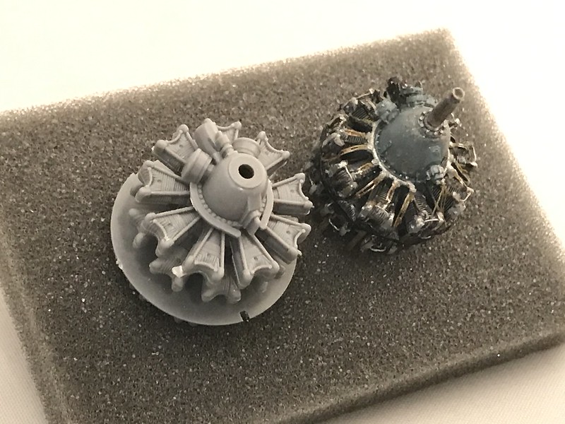
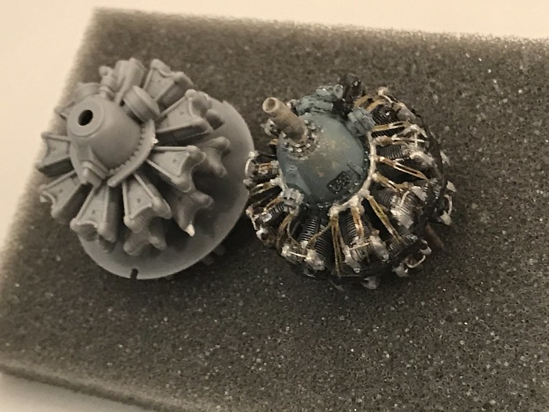
Anytime I get the opportunity to feature the engine I am sure to upgrade this part in some way or another. If there are too many shape issues to overcome or if sanding and cutting will take too long and become too much hassle, I’ll turn to AM for a handsome replacement. That tends to be the case with radial engines and as they’re quite visible I like to display as much detail as I can cram in there. A while back I found an Aries R-2800 (early) engine on ebay for about $10 which is quite a steal. I knew there would be some modifications to make in attaching the engine to the fuselage but after opening the box and sizing it up I realized I’d have to make a few more. I originally intended to fashion some exhaust stacks as well, but I’ve recently scrapped that idea as the dimensions of the kit and default thickness of the plastic won’t allow a clean transition and the fact that they will be hidden behind cowling piece that shields them. So for sake of contrustion ease I’ll come up with an easier solution. There’s a Quickboost engine fitted for the Tamiya kit that will work just fine for most. I was looking to replace the kit part exhaust stacks in some way while I bumped up the detail around the cowl flaps so I opted for something different. The detail of the Aires engine is very nice and makes a nice addtion to your Corsair.
 Untitled by Britt Vallot, on Flickr
 Untitled by Britt Vallot, on Flickr
I’m throwing the Vector cowling set into this build as well. One part lazy on my end and not wanting to scratch out 20 different sets of cowl flap actuators, and one part I want redemption from the first set I used years ago on my last Corsair where I didn’t pay close enough attention to how the cowling ring mounts were spaced. Plus, I hadn’t recognized that the cylinder heads attached just posterior to the mounts. The Quickboost engine I used sat a little bit too deep from this junction and there was too large a gap to properly connect them and it slipped my notice. So, this time around I’m going to get it right.
As I get closer to marrying the fuselage halves together, I’ll go into more depth about how I’m attaching the engine.
 Untitled by Britt Vallot, on Flickr
 Untitled by Britt Vallot, on Flickr
 Untitled by Britt Vallot, on Flickr
I realized after reviewing these pictures that I’ve place the inter-ear oil drain pipes for the rear cylinders on the back end of the cylinder. They should be front facing. I was rushing through this part and wasn’t paying attention obviously. There’s a few things still to add here…rocker box oil sump at the very bottom middle front cylinder and the oil scavenge pump pipe and a few other random cables and such.
The Cockpit
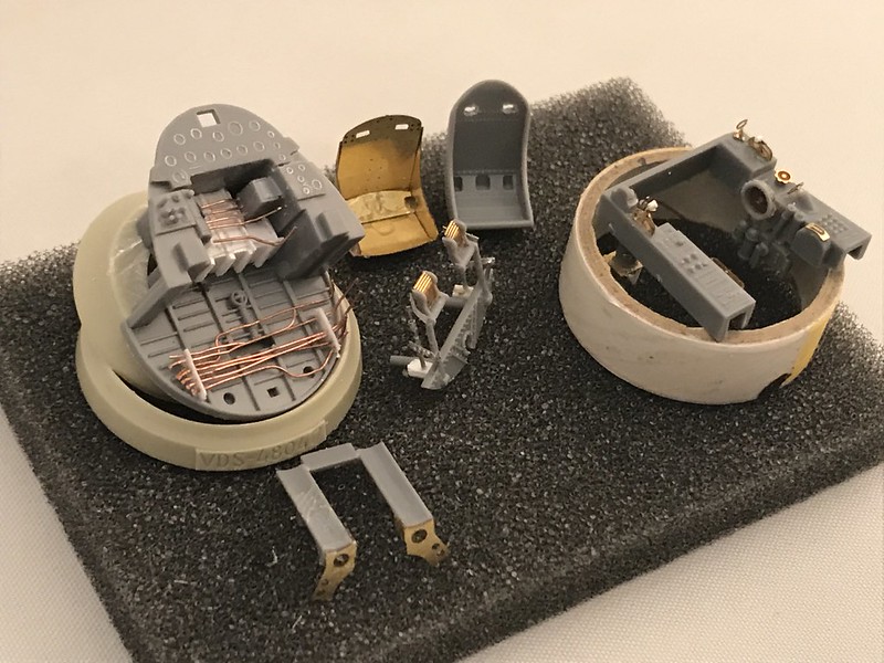
I plan to walk through some of this a little bit as there’s always more that can be done to tweak things but the Tamiya Corsair cockpit already is a pretty decent cockpit at 1:48. I wanted to see how Eduard’s PE would match up for the detail set so I had grabbed one that I saw cheap on ebay about a year ago in anticipation of this build. I normally don’t like how PE works for certain features within the cockpit because of its two dimensionality, but there are some things that are of use and the rest I plan to scratch out.
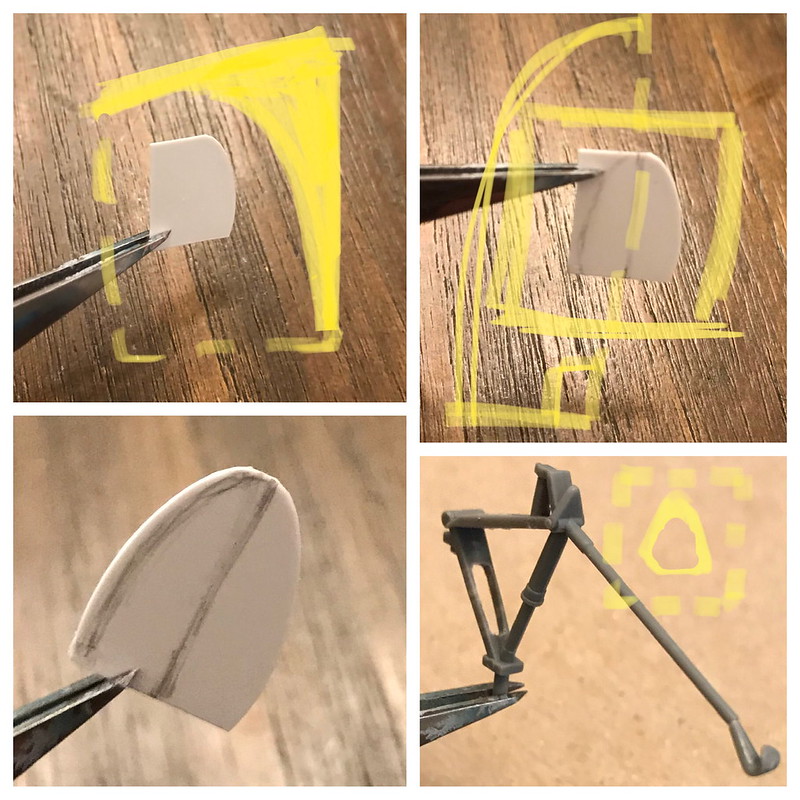
First, I’ll start with removing everything I plan to fix. Much of this gets to stay as I’m quite pleased with how Tamiya put this office together. It’s really not too bad, and that’s coming from me. If you’ve seen my previous WIPs you know I like to cut it all out lol. I started with the seat. I’ll build up all of this myself which ought to really help tie all this together as the seat is always the most prominent feature.
 Untitled by Britt Vallot, on Flickr
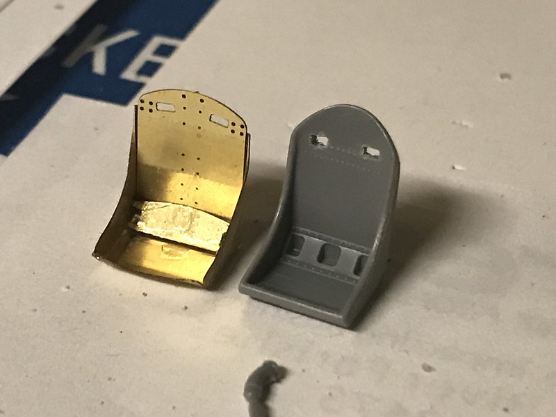
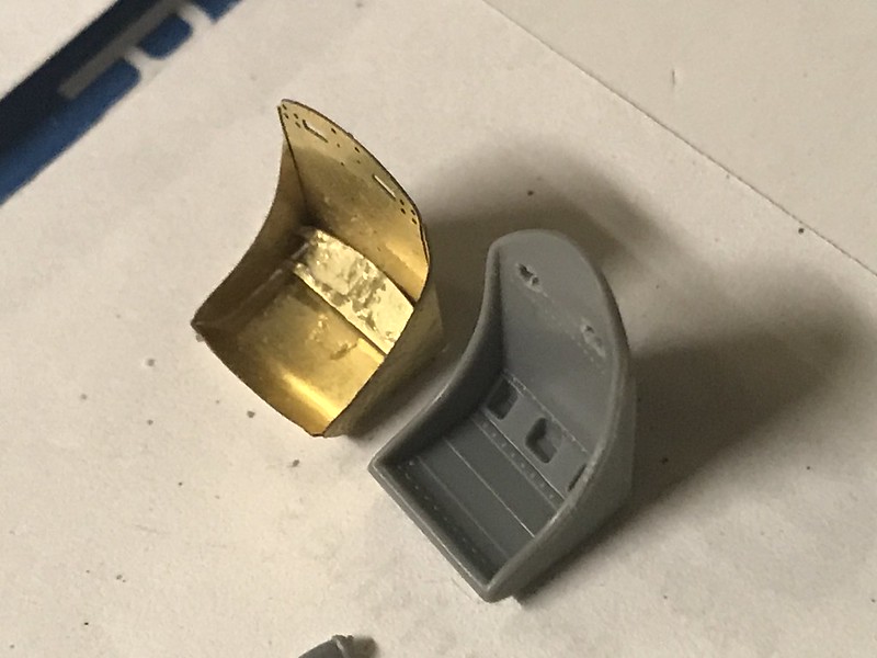
Next, I went after the office chair and again I have to say I favor Tamiya’s seat better than the PE. Didn’t think it was going to go that way but I saw after some strategic sanding I could come out with a much better looking seat than what the PE offers. There’s just not enough depth that comes out of the PE.
 Untitled by Britt Vallot, on Flickr
 Untitled by Britt Vallot, on Flickr
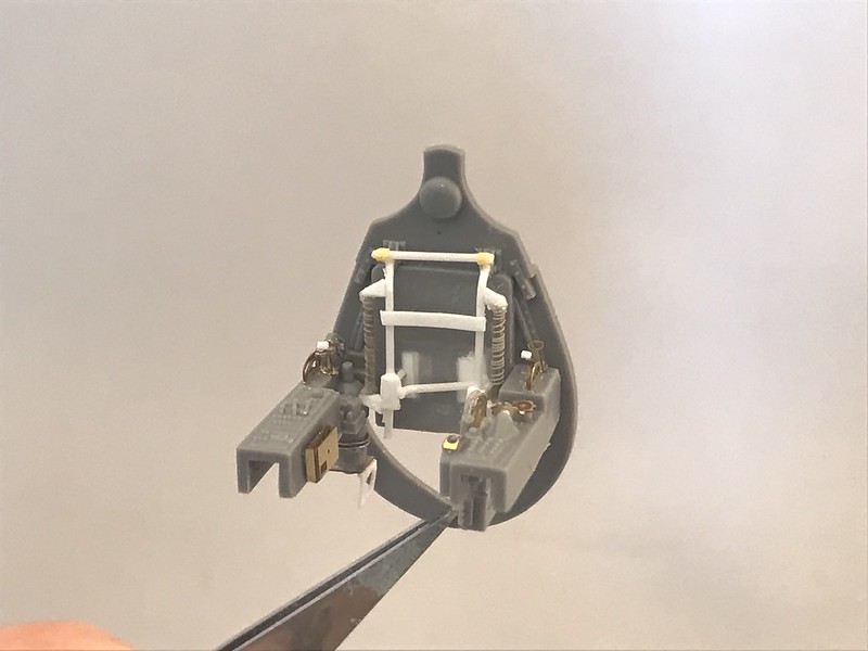
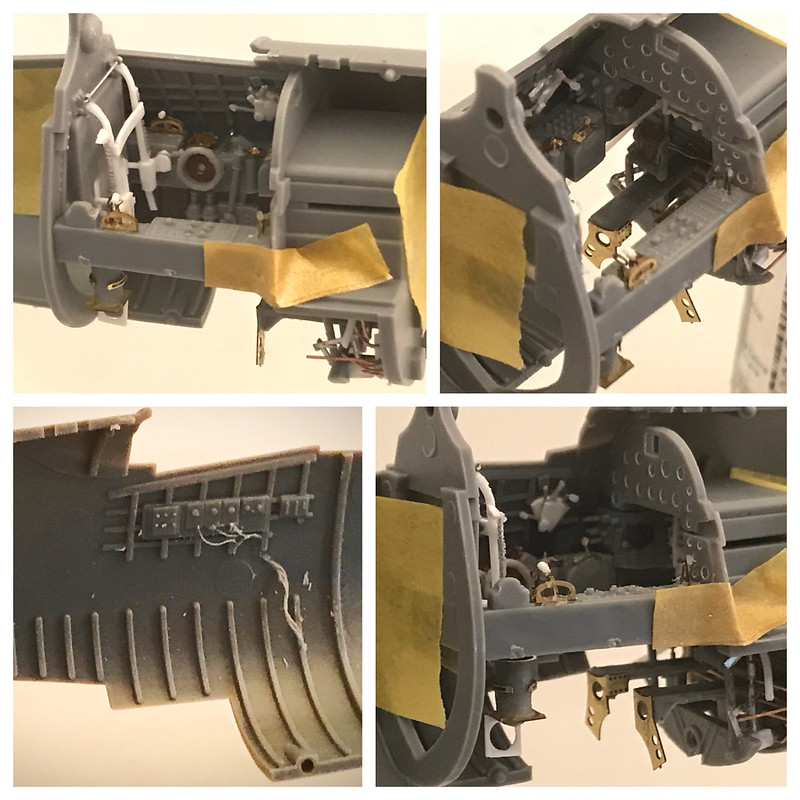
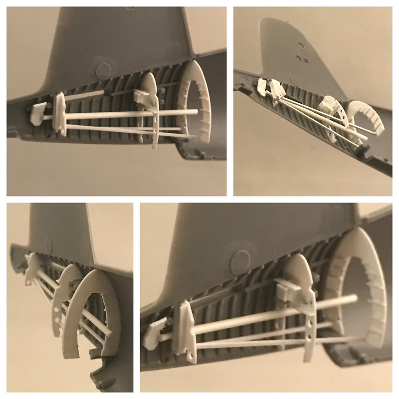
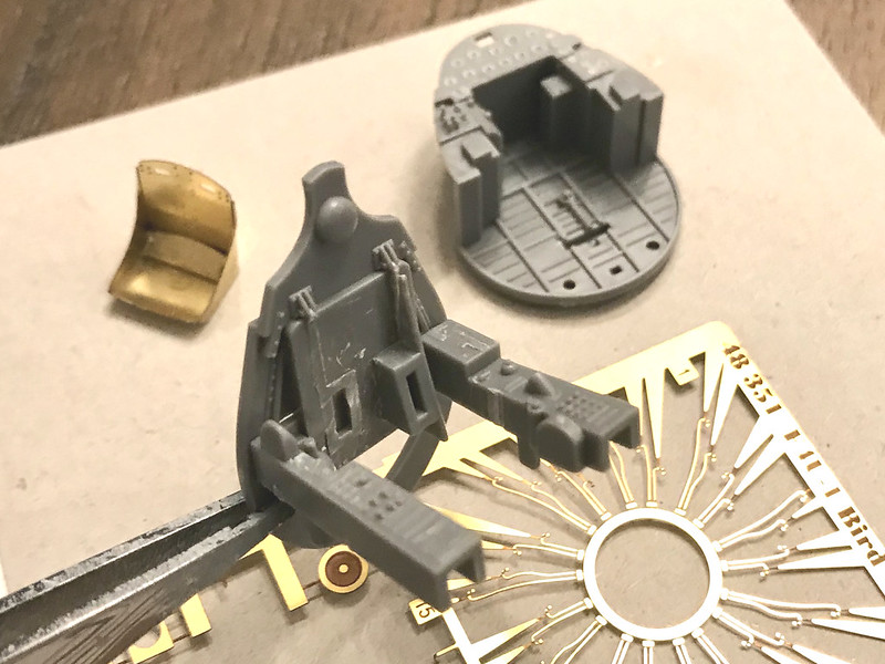
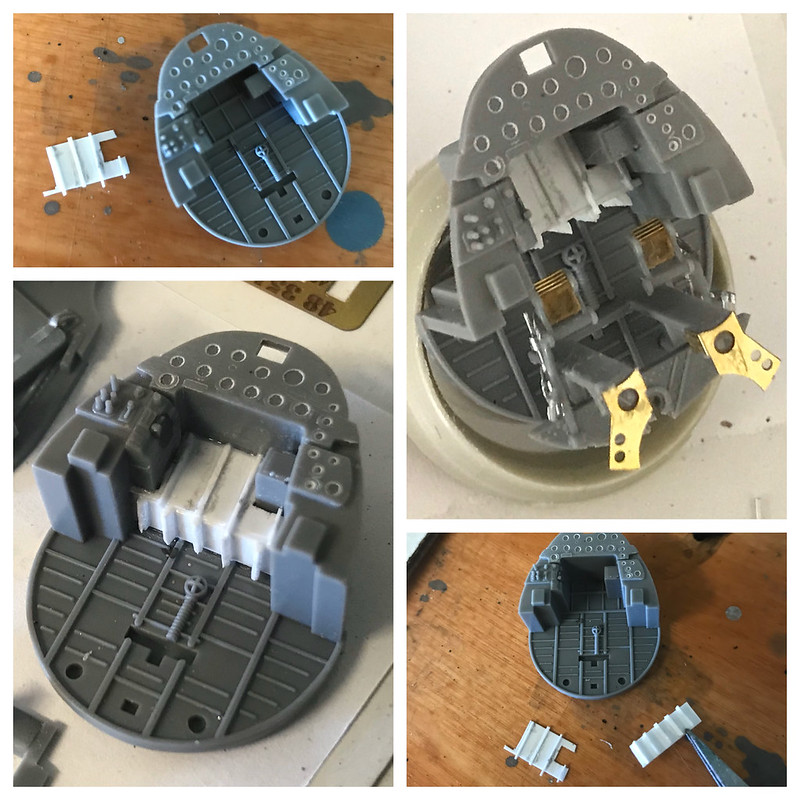
Next thing I focused on was the front of the cockpit below the IP. This region should come forward just a bit. It will hardly be seen when this is closed up but it will offer for a little extra detail to be seen that would most certainly be lost in the shadows. It’s built up as seen below. The bottom frames are standing a little too proud here and I shaved them down later on you’ll see.
 Untitled by Britt Vallot, on Flickr
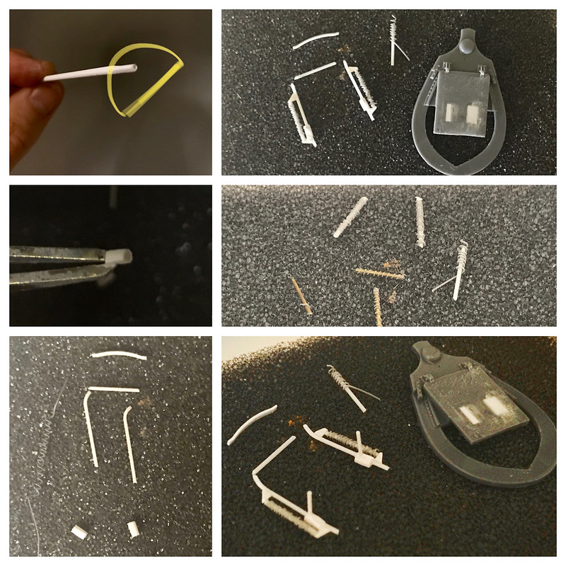
I turned my attention to the rudder pedals and added the brake mechanism. This will likely not be seen well either but hey…you’re not on this forum because you wanted to see snap-tite kits, right. Here is a simple arrangement I made from some slide tube and lead foil. Easy enough.
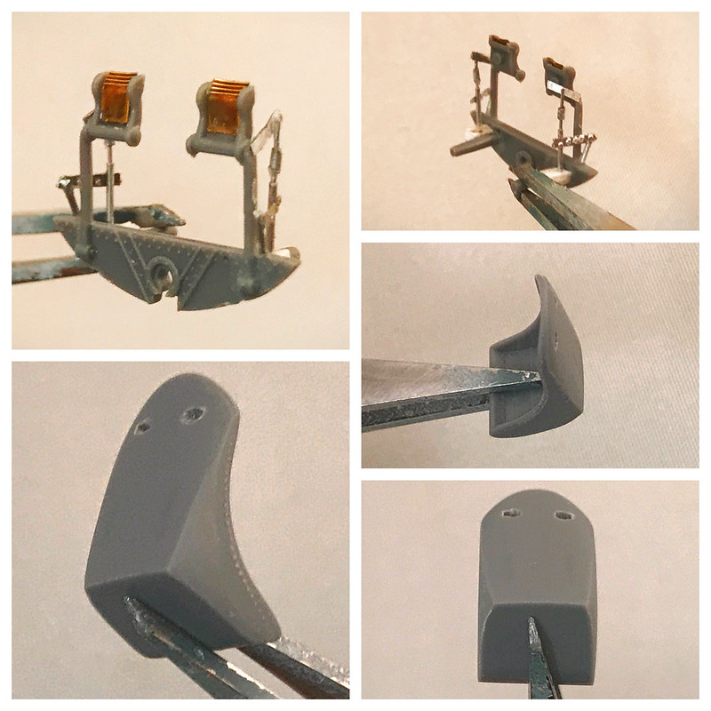
The chair was sanded after a few handy photos I managed to find of some cockpit photos of busted up Corsairs and the Eduard Brassin resin pieces believe it or not.
 Untitled by Britt Vallot, on Flickr
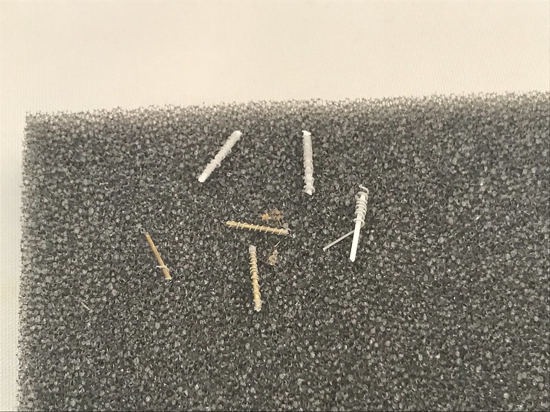
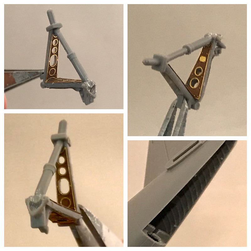
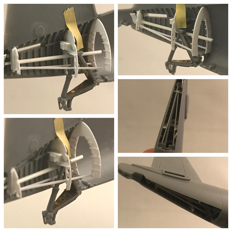
I later began to move through some of the PE pieces I would include as seen below. The primer that adheres to this actually does tend to give items like these a little bit of height. I think it’s just enough that I’m fine with including it. Next, I moved on to getting the wiring rigged up for the front bulkhead below the IP. I had to change up the arrangement some for the bottom set to make room for the rudder pedals and feet stands.
 Untitled by Britt Vallot, on Flickr
You can note the larger trim wheel got an extra strip of stretched sprue to wrap around the PE piece. I carefully curved and bent down a small length of stretched sprue and cut it at the appropriate length and glued it together with Tamiya Extra Thin Cement. Held it together with my fingers to keep it biting down while it fused.
 Untitled by Britt Vallot, on Flickr
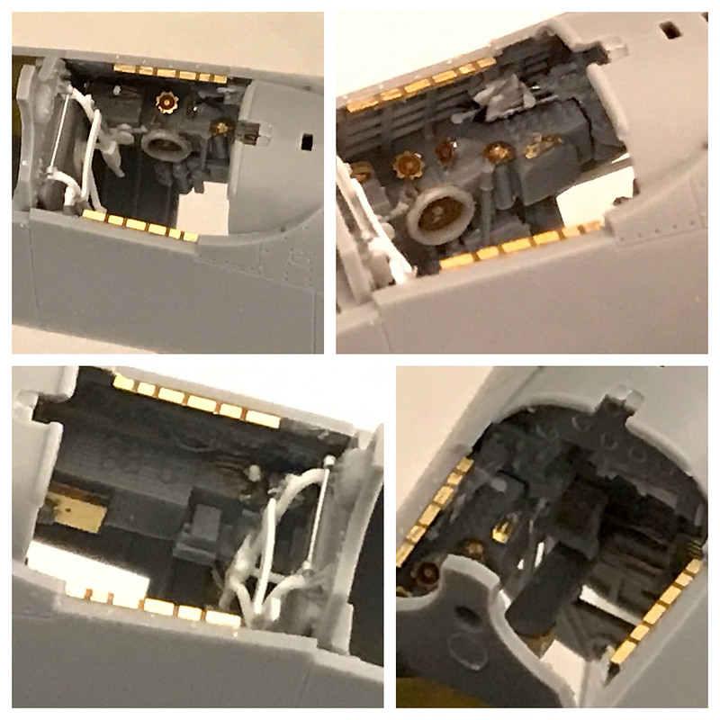
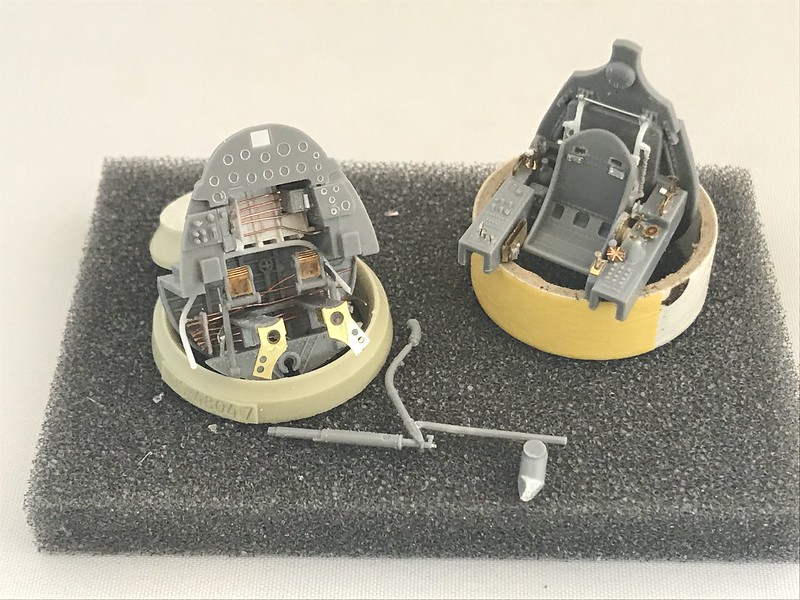
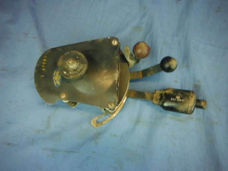
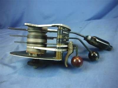
Here is how all this is starting to set up. I’ve also filled in the holes that were left from cutting out the kit molded seat features. I also CAed the gaps and sanded this smooth. The semi-circle PE parts on both sides of the controls I believe are wing fold locking controls. There is a somewhat larger nob that I’ve tried to better represent here. The PE parts just don’t quite get it done.
 Untitled by Britt Vallot, on Flickr
That’s a wrap for now.
Comments and questions are always welcome. =]