Tamiya 1:32 F4U1-A1 Corsair Build Thread

I’ve had that happen too. I search and search for a missing sprue only to find there are several sections molded into one sprue. Arghhh…

Your corsair is looking fantastic. Great work in the cockpit, and the figure too. I keep wanting to add figures into my builds, but always chicken out.

Cheers, Mark

Thanks! Tamiya includes nice figures. SWS has great figures too, but you have to order them on the after-market (+$$$).

Today was a milestone day: fuze joined. Before doing that there were a bunch of details that needed to be installed on one side or the other. In the aft portion, there were brackets, blocking pieces for the tailplane joining area, and four bulkheads and added details including the elevator bellcrank and actuating lever. Some of these pieces I had airbrushed on the sprue, but still had to hand paint some interior green to finish it all up.

On the cockpit starboard (R) side there was an group of switch boxes held on a piece of flat PE with some CA. Two of the three pieces were dropped. I found one on the shelf at the bottom of my roll around work bench. The other was apparently gone and after I swept about 25 square feet I gave up. Then later, I see a little black speck at least 10 feet away and there it was. So I got all three installed and mounted to the fuze side. There’s even the flare pistol which I painted exactly according to the plans plus wooden grips.

But… all of this wonderful detail is totally invisible as evidenced in the next group of pics.

Joining the fuselage was a joy! Even with all that stuff inside it just popped together. The seams are almost invisible. If any filler is needed, it will be very little. Then there were several panels that also fit perfectly.

The cockpit opening is narrow (almost claustrophobic) and you can see almost nothing of all that fancy painting I did. I pity the guys that go the next step and run simulated wire runs to all the side switch boxes, also which will never be seen. The only seam that may need some work is the one immediately in front of the cockpit.

Here’s looking up in the tail section. When the tail wheel and arresting gear are installed and then partially occluded by the gear doors, most of this won’t show up either.

The last work I did today was paint the fire wall Tamiya Bare Metal Silver spray and install it. In this image you can see the beautiful fits on the front panels.

This same step had the exhaust pipes joined to the fire wall… at least 2/3 of the 6 pipes. The last two get installed just before the engine is mounted. I wanted to air brush them Tamiya Dark Iron as a base coat and needed to hold them. While the outlets are beautifully molded with the impression of an opening, I drilled them with a 0.032" drill and use some wire of the same size to hold them for paining. I will enlarge this hole just a tad to complete the illusion that these are, indeed, exhaust pipes.

After painting and weathering I will mount them to the firewall, which itself needs some weathering before the pipes go on. This model is moving along nicely.

Last night I gave the okay to laser cut my next model railroad building, so after the Corsair is built, I’ll be back at railroad work.

its coming together and looks great.

That looks great! Another kit on my short list. I’ll be following this one.

It’s a great kit. Now I have my eye on either the Tamiya FB-VII DH Mosquito, or an SWS A-1H Skyraider. I have limited display space and I really need to build things with folded wings, which the Mossie has not. Either way, they’re all fabulous models.

Went to the LHS to get some maintenance items: Tamiya masking tape, CA glue tips and some graduated plastic mixing cups. So I got to work around 2:30. Got the exhaust pipes air brushed and installed on the firewall.

Before installing the pipes, I dry-brushed some flat black and added some weathering powder to the sheet metal trough where the pipes exit. Then I air brushed the pipes Tamiya Dark Iron rubbed with some Rusty Brown weathering powder; not much, just enough to change the hue. And or course, you won’t see anything but the tips which I painted flat black. I used my new Point Zero detail air brush for this. The nozzle is very fine and keeping it clean is not easy. There is another set that doesn’t get installed until the engine is installed.

Instead of painting the engine parts separately, I sprayed/air brushed/brush painted all the ones that I could while still on the sprue. This pic shows the color selection. The cylinders are rattle-can sprayed Tamiya Bare Metal Silver. I then sprayed the intake pipes and pushrod tubes Tamiya Semi-gloss Black and the exhausts the same as the pipes on the firewall. I looked up the R-2800 on the web and saw that the gray can vary quite a bit. I took Tamiya Neutral Gray and added a lot of white and made a light gray.

Some very fine details need to be picked out before removing the parts from the sprue such as the bottoms and tops of the push rod tubes are shiny, there is a black band around the bottom of the cylinder head to the lower cylinder, the valve covers are shinier than the cylinders, and then there’s the provisions for spark plug wiring.

I have some Albion Metals very tiny brass tubing that is going to serve as the ends of the plug wires entering the cylinder heads. I used these the first time when detailing the wing fold area on the Avenger, so I’m comfortable cutting and handling it. It’s best to cut it on some masking tape so the pieces stay where you cut them. You roll a sharp #11 blade back and forth to cut it. If you don’t add any extra piping or wiring on a model, the least you can do it put the sparkplug wires on a 1:32 kit.

The lower cylinder has a slightly different cast than the heads, and all the fins need some seam treatment to set them off.

My daughter asked my wife and me to help her do some election day canvassing and it was a beautiful Fall day here in the L’ville, so we did it for a couple of hours. It took away some of the stress of waiting for election results and gave us a chance to get some fresh air. But I did get to “work” on the Corsair at around 2:30 and got to work on detailing the R-2800 engine.

I started by drillig the spark plug locations on the front cylinder (part 5) using a 0.021" carbide bit which is the hole size to recieve the piece of small brass tubing for the spark plug wire. I also, drilled out the two lugs up near the valve covers which will be the mounting place for a cross-over tube, that I don’t know what they do, but it’s a neat detail to add. This is a photo of a 1:16 scale R-2800 model that was offered (built-up) by Fine Art Models a few years ago.

Here’s another pic of the actual engine.

And here’s another shot showing how the spark plug wires lead to the back of the front row and the other set to the back row. Notice, the wire goes through the black sheet metal shield (which the model includes) which completely obscures the plug connection to the back of the front row. So I’m not going to worry about any super-detailing anywhere but the front of the front row. Notice also that from the side of the cylinders all the way back there is another sheet metal shroud that directs airflow closely around the front cylinders and provides a more uninterrupted path to the rear cylinders. These shields are never provided in model engines. Modeling with wine bottle foil would be possible, but not necessarily useful.

The R-2800 has two distributors and two plugs per cylinder, not for system reduncdency, but to manage the flame front across the cylinder and prevent engine knock. By firing plugs on both sides of the hemispherical combustion chamber it precludes the flame front from compressing the charge to pre-ignition temp before you want it too. And, NO, Chrysler was the inventor of the Hemi…

After drillig the holes I tinted the fines starting with Brown Tamiya Panel Liner to color the lower cylinder area and Tamiya black liner for the head areas. I then hand painted that black connecting seal between the head and cylinder body.

The Albion Metals tubing I’m using for the spark plugs has a 0.021" O.D. and nicely accepts a 0.010" plug wire. To cut this tiny tubing I laid down a piece of double-sides Scotch tape and rolled a single-edged razor blade back and forth until the tube separated. The sticky tape contains the tiny tubing piece so it doesn’t go into the quantum rift. I then threaded them onto a piece of high E guitar string so they wouldn’t get lost.

Not only did the guitar string contain the parts, but it served as a guide to enable me to place the tubing over the hole in the engine and push the tubing in using a tweezers.

The only thing I didn’t get right in putting the tubes in is some are in deeper than others. I should have had a gauge to stop the pushing at just the right moment. If I do it again, I’ll do it different. Funny thing happened… I had a bunch of tubes cut and threaded onto the guitar string, but not at the back, up front. I had the string on the cutting pad arranged for a photo, when the string fell to the floor, and, of course, every single piece of tubing was launched into the rift never to be see again. So I had to cut a whole bunch more to take the new picture.

For the cross-tubes, I originally was going to use the brass wire I’m thinking about using for the ignition wiring, but it was too soft and couldn’t hold shape. I measured the distance between the holes using the tapered jaw width of my ChannelLock long-nose pliers, and marked the jaw at the selected width. I then was able to bend many copies of high E guitar string (piano wire) to the hole spacing. I drilled these holes with the #86 (0.011") carbide and it was an expensive operation. These tiny drills are about $1.50 each and I broke three of them.

After inserting the wire I put a drop of thin CA at each hole to hold everything in.

Nice work here, as usual.

The tubes are oil drains for the rocker shaft housings. The two independant ignition systems surely have a effect on the flame front during ignition but the main reason is in fact redundancy.

WOW your engine detailing is amazing. TY for the W.I.P. on this as I want to build oneof these puppies and I’ll use this as a referance if you don’t mind.

I’ll accept your input. I did read that the two sparks were essential for operational effeciency, but certainly redundency was equally as important. And I did find that in the R-2800 maintenance manual they’re referred to as “Inner-Ear Drain Tube” which almost sounds comical.

Part of the reason I wanted to build this model is building this motor. And the cockpit. One of the real bummers about building UCAVs is no cockpit… Boring! They have landing gear, but otherwise, there’s not much going on.

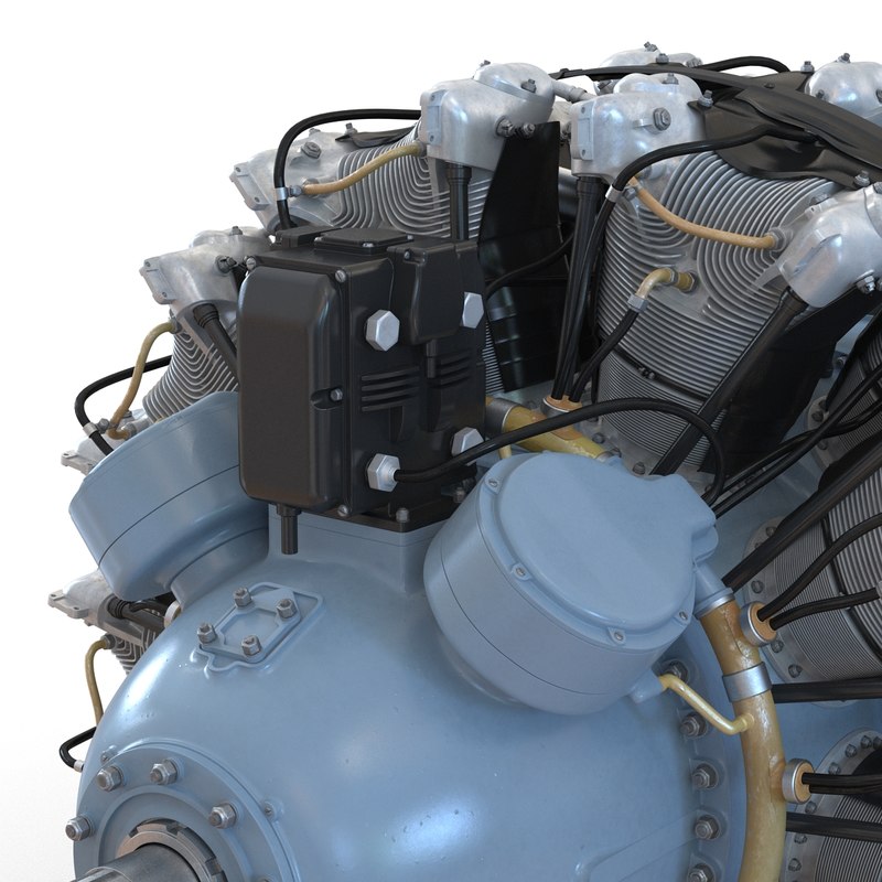
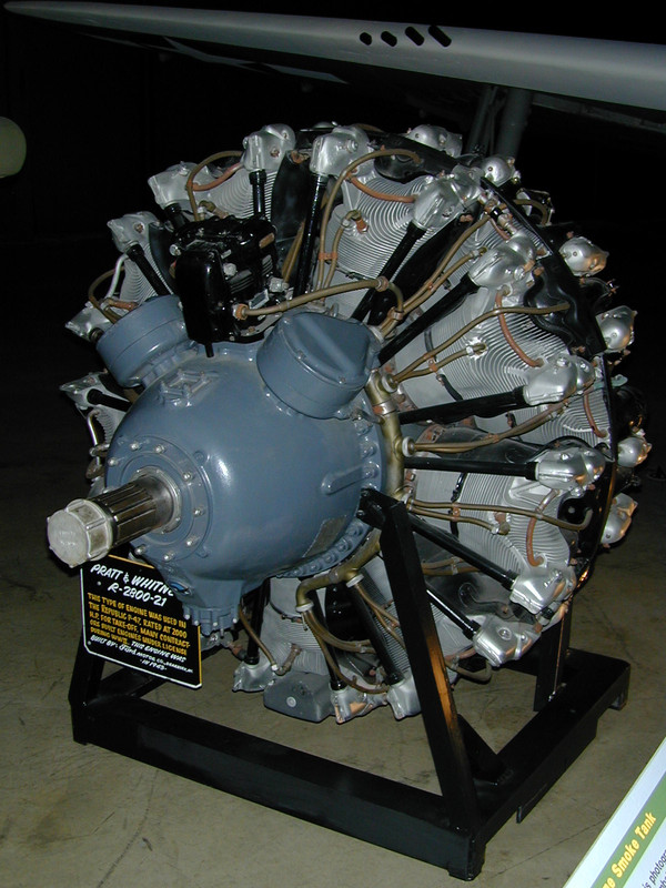
One of my pictures yesterday was not an image of the Fine Arts Models r-2800. Instead, it is an image from a company that produces super-realistic 3D computer images. That firm is TurboSquib, an Internet-based company that offers very fine 3D models to the trade by various artists world-wide.

Today I almost finished installing the ignition wiring. I erred in not drilling the spark plug holes in the forward face of the back set of cylinders, since I now had to do it with the engine assembled.

I used the Molotow Chrome pen to pick out some bolt heads and the upper and lower clamps on the push rod tubes.

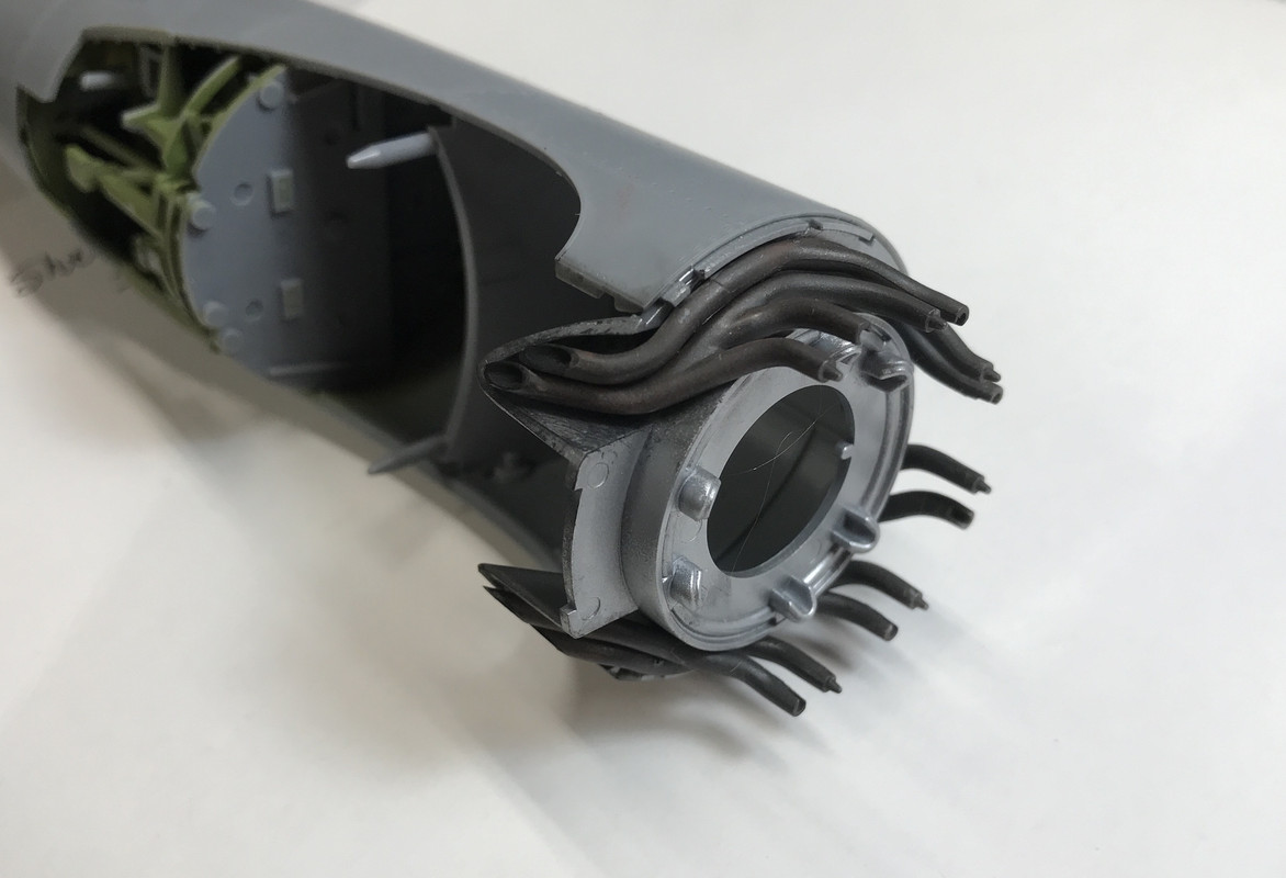
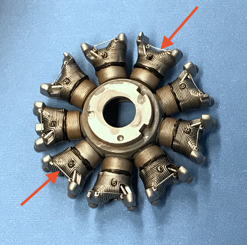
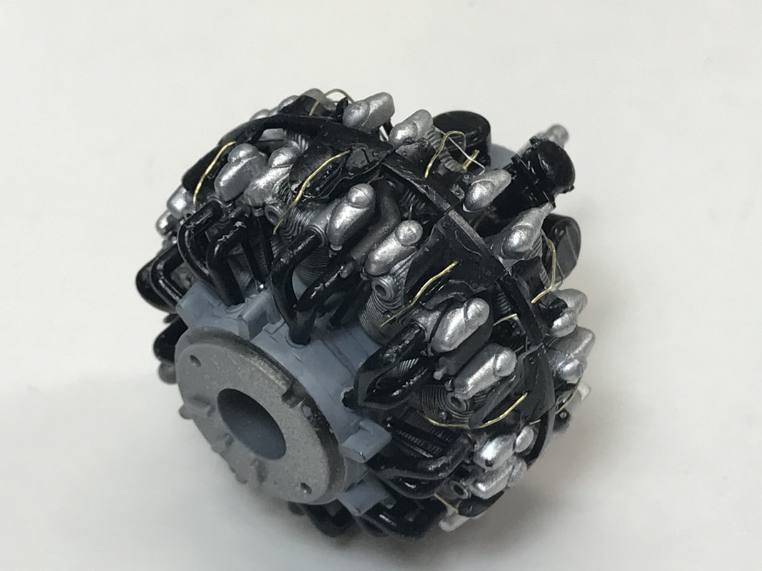
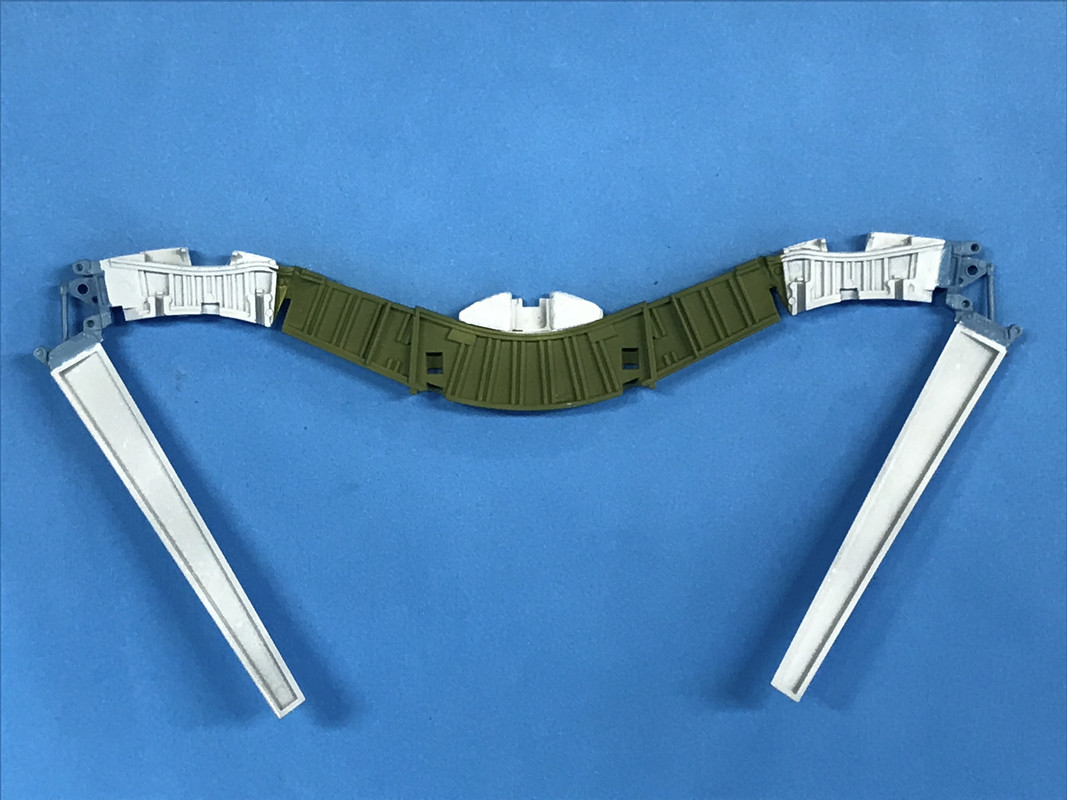
I assembled the engine starting with assembling the inter-connecting intake and exhaust pipes to the back of the forward bank. These are two-part affairs that are glued together and then you need to touch up the semi-gloss black of the intake tubes if you do what I did and airbrush the exhaust parts when they were on the sprue. Part of that piece is a section of the intake tube.

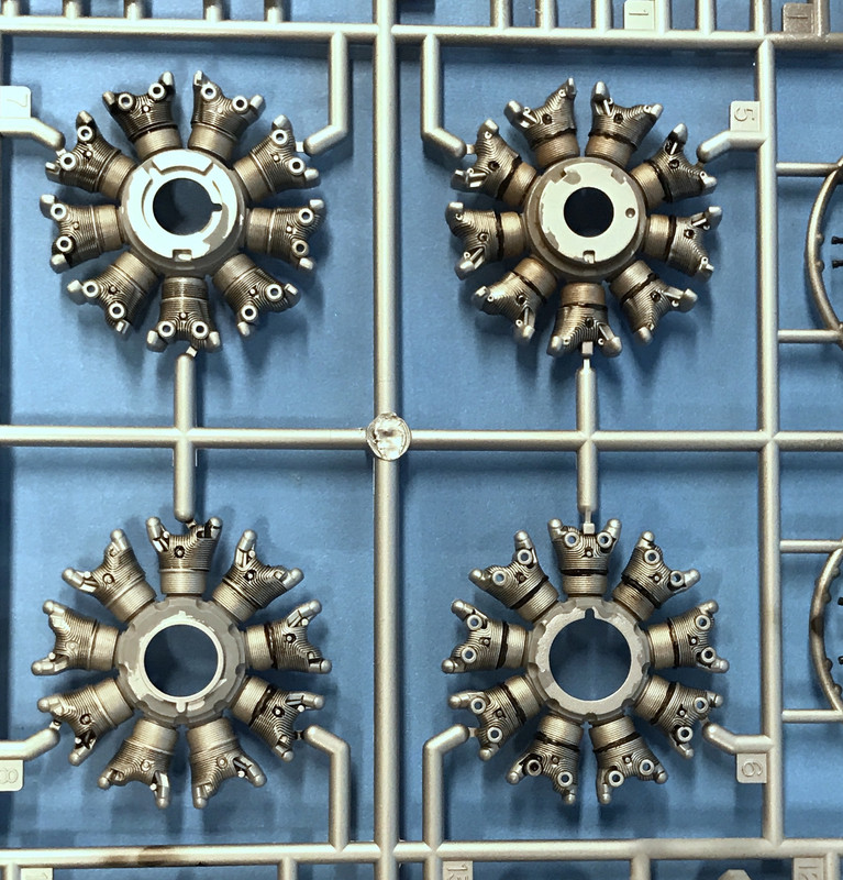
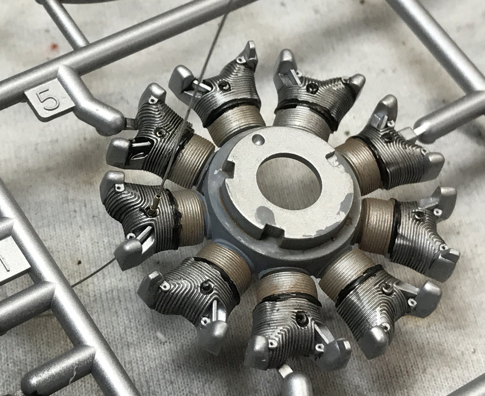
The rear cylinder bank went together very easily. Tamiya has been doing something that Trumpeter ought to learn. They connect the sprue gate to the rear of the part, not the side. There is no nub on the side that, when removed, can damage the part. Instead, the nub is on the rear gluing surface and is very easy to remove. To this rear bank I first installed the rear pushrod tubes, and then the rear engine case that has the intake tubes that exit from the supercharger housing. The rear engages with the front bank with a keyed inner ring and engages with the intake tubes that are coming from the front bank. When they do, the whole deal just pops together.

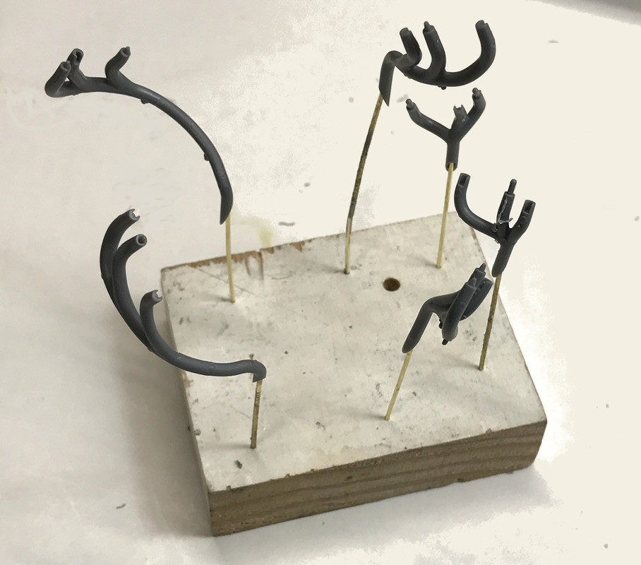
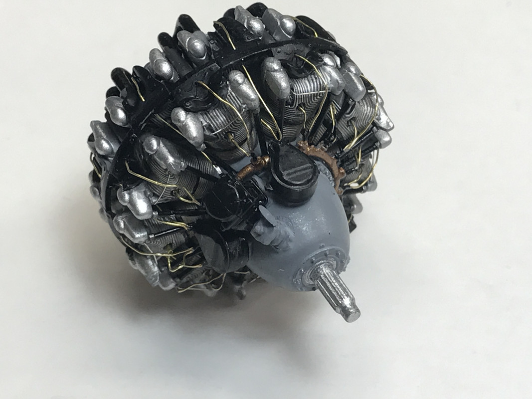
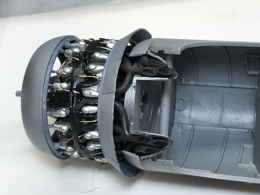
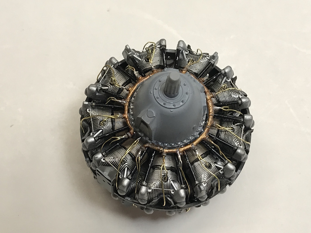
With the engine assembled I needed to prepare the ignition harness ring. This part is smaller and more frail than I would have liked. In fact, before I got it fully removed from the sprue it broke in half. I repaired this break by carefully drilling 0.021" to both ends of the break and CA’d it back together with a piece of same-sized phosphor bronze wire. I then had to drill the very small connection points (16) with the same sized drilled. Two wires eminate from each connection point. It was very dicey since the top of the connection point was wider than the little tube that connected it to the ring. Some of the holes went down the center, but a couple broke out of the side. I was almost going to plan B, by using and actual piece of copper wire to make this part, but I persisted with it.

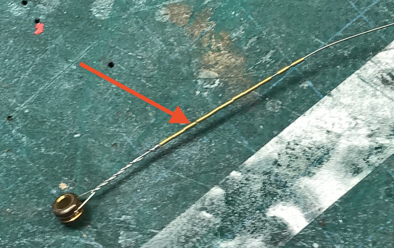
For the wires, I chose 0.010" brass netting that was on the top of some Italian Montepulciano D’Abruzzi Tuscan wire. It was a twisted net with all the wires intertwined with each other. The two wires twisted together were 0.021" which is the same size as the holes I drilled and I actually wanted to use the twisted part too.

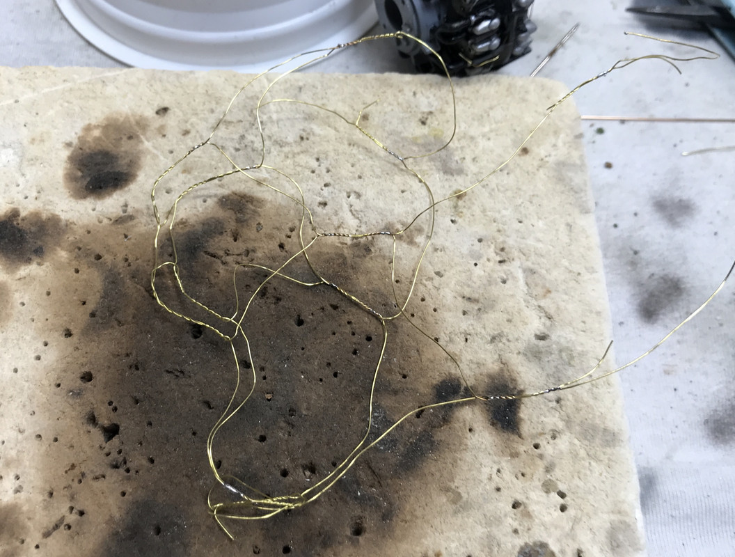
To keep the twisted part from unraveling I soldered the twist just before it separates into the individual wiring. I was able to use the twisted part to anchor the wires into the holes in the ring and then captivate them using thin and medium CA plus a bit of accelerator.

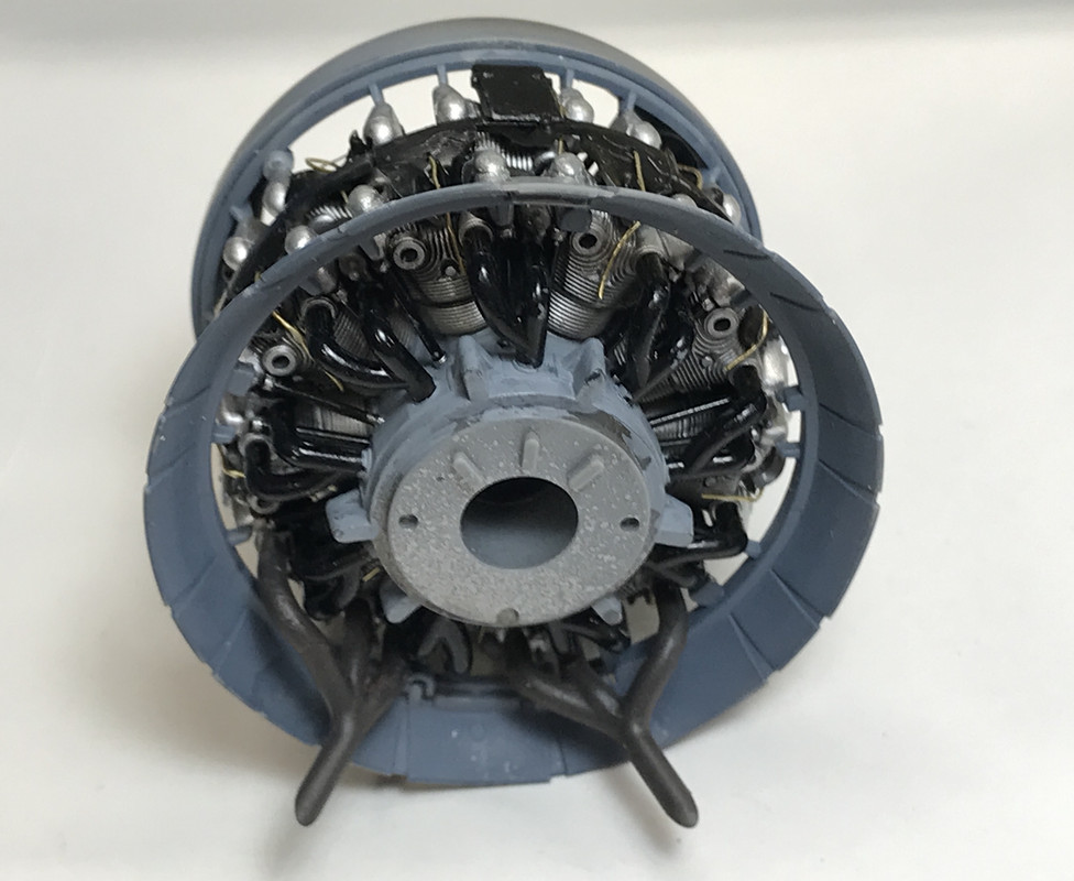
I planned ahead with the cylinder head baffles by drilling the ignition wire pass-through holes before painting and separating them from their sprues. I then airbrushed them semi-gloss black and, when dry, glued them in place.

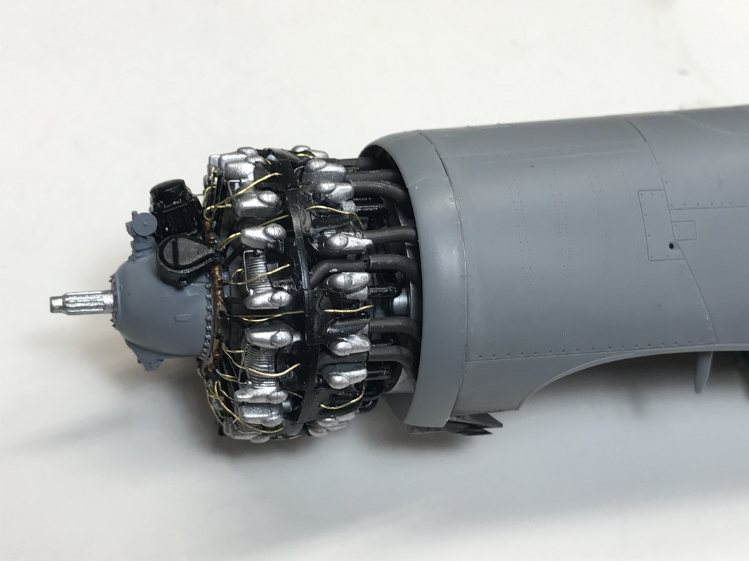
The rear wire for the front bank goes through the hole and then bends down out of sight. The front wire for the rear bank goes straight back to the plug since it’s right in the middle of the cylinder facing you… although it’s tricky to get the wire into the hole. The rear wire for the rear bank goes through its hole and drops down behind the cylinder. It could be belayed into the spark plug area in those cylinders if your inclined to insanity since it will be completely hidden by the cowl. Even if you use the transparent cowls included in the the US version of this kit you probably won’t be able to resolve where these wires are ending up. Although if I have a cowl in an open position you might see this termination, so I may terminate those that would be seen.

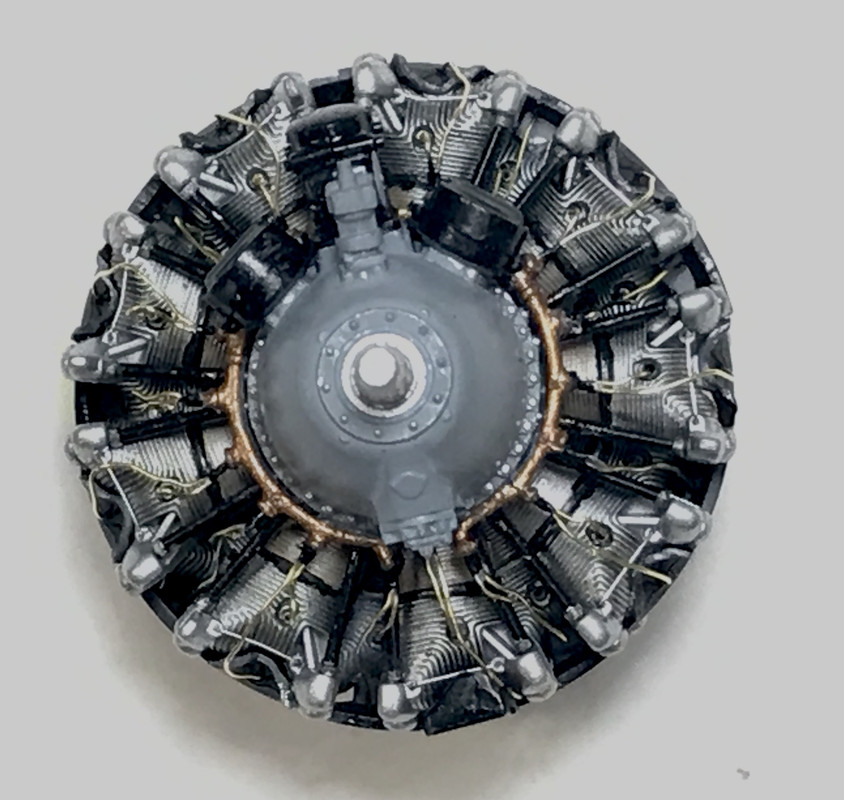
Here are the first four wires in place.

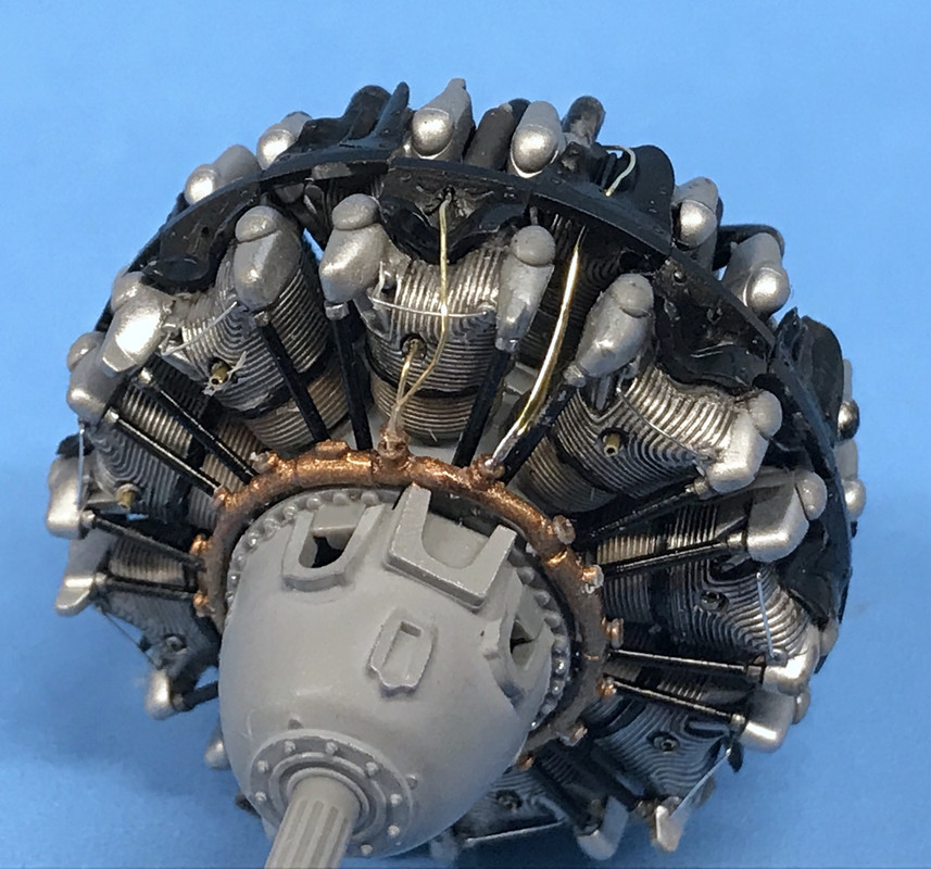
I got all but two wires in place before my session ended today.

What still needs to be done is touching up the ring, the junction of the wires and the ring, the baffles (where the sprue connection was) and anything else that got worn. I’m also going to specifically paint the rocker covers a shinier metallic finish to differentiate them from the rest of the cylinders.

1 Like

As I would expect, but am continually impressed by, your work is exceptional.

And, since it’s a corsair F4U, I’ll be following along looking at your amazing building prowess and enjoying every moment.

Wow! That engine is superb and you have shown me a new way of doing the ignition harness which I had not considered before.

I just wish you could also include metric measurements as well !! :slight_smile:

I have Zoukei-Muras Shinden in 1/32 ready to start and their new 1/32 Ki-45 booked to collect at the IPMS Telford Show on Saturday.

After seeing your wire work I am going to have to up my game and the Shinden will be an excellent learning opportunity.

Thanks for showing the technique

James

That engine is looking good, especially around the cylinders. Are you planning on detail painting the reduction box?

Well… thank you! 1:32 compels you to do more. I did the same level of nonesense in my 1:48 B-17 which had Eduard upgrades on all four radials. That was nuts! In 1:32 you at least have a fighting chance, but you’re still drilling really small holes in really thin pieces of styrene. It’s not for the faint hearted.

Got in the shop late today but got that last ignition lead installed, touch up painted the whole deal and added the last parts. The engine is complete and ready to go into the air frame. On the Trumpeter Avenger, not only was the engine detailed, but they included all the behing-the-firewall gear case stuff and engine mounts. These were then buried behind the skin. In order to show it all off I had to cut open the skin complicating the build considerably.

For some reason, the distributors didn’t fit over the ignition ring properly and I had to doctor them a bit some they nestled in. I also added the magneto, the prop governor and the little part at the bottom which has something to with the oil sump.

These parts were supposed to be light gray, but I left the distributors semi-gloss black as I’ve seen in my pictures. Theoretically, there is some wiring that goes to an from the magneto, but enough it enough. This engine is done.

I painted the valve bodies Tamiya chrome silver, and touched up the rest. Interesting about Tamiya paint… unlike normal acrylics, which when dry can really be reconstituted, Tamiya when dry can be sort of brought back to life with isopropyl alcohol. It’s not perfect, but it let me re-use a little bit of the light gray I mixed that had totally dried in the little epoxy cup I used as my mixing bowl. I was able to use it to touch up the gear case and paint the few added pieces.

And lastly, I stuck the engine onto the airframe to see how it looks. There are some cowl pieces that need to go on before gluing it in place, and these parts have to be painted dark gray in their interiors (although I have no idea why since they won’t be seen). I am contemplating either using a clear cowl piece to show off the hardware, or put one of the pieces in an open/upward position to do the same thing. There are some of the front bank exhaust pipes that are not aligning perfectly with the pipe extension leading to the outlet.

Hard to believe that a power package that little put out 2,000 hp or more. By the end of the era for the 2,800, they were getting 2,800 hp out of it. That’s 1 hp per cubic inch. Now to put that in perspective, top fuel dragsters are now getting almost 10,000 hp out of a basically 400 cu. in. engine, but they last for about 1 minute of running time. The 2,800 was running thousands of hours putting out that energy. If you don’t want something to last more than a few minutes, you can get a heck of lot of HP out it.

Once the cowl pieces are fit, I’ll be moving on to the flight control surfaces.

I would use the clear cowl but paint the right hand side, leaving the left side clear. This way you can have a full paint job on the right side and still see the engine on the left.

it does take some careful masking and painting but with that engine, well worth the effort.

James

The cowls are split top and bottom, so I’ll leave the top clear and the bottom painted. The clear parts have a slightly frosted texture which tamiya has included on all the skin parts to give it a better paint adhesion. They recommended and I did dip the clear parts in Pledge and will check them out on Monday after they completely cure.

After studying more images of the R-2800 I noticed two other prominent pipes that could easily be inculded since they’re right in the front bottom of the engine and could be seen through the wide open cowl. These are oil scavenge lines that lead from the oil scavenge pump that sits at the bottom of the gear case and goes to the oil receiver at the bottom onf the front cylinder bank and the other goes back through the engine and ends up probably at the imaginary oil tank. The smaller lines is copper colored phosphor bronze and the larger a piece of 0.032" brass, both of which were made chrome by the Molotow Chrome pen. Now the engine’s done! Whoops I just noticed that I didn’t put on the PE builder’s plate. I can do that through the open cowl.

With the engine complete it was time to install the forward cowl leading edge and the open cowl flap ring. You can have it will the cowl flaps open or closed. I chose open since it shows off more of the exhaust spaghetti. As usual the engineering was excellent in locating the cowls to the engine, but becuase I had painted the lugs that tie the valve covers on selected cylinders to the rings. So the glue was having trouble getting a good grip. I ended up helping it along with CA.

The remaining two exhaust collectors were put in place and then the entire engine was joined to the fuselage by using tube cement just on the center ring which has the heft to provide a good joint. The cowls varied depending on whether you’re doing version A, B or C. The “Big Dog’s” Corsair was the earlier B version. This plane had opening cowl flaps at the 11 to 1 o’clock posirtions. These were eventually closed off permanently when the airplane had the habit of fouling the windsceen with leakage from the engine. The B model also had the original shorter tailwheel. It was raised in subsequent models to give the pilot of better view forward over the huge nose for carrier use. The long nose was the reuslt of having the fuel tank in front of the cockpit. A couple of tiny PE pieces help hold in the opened top flaps.

I liked how the new exhaust pipes nested into the others that were already in place.

This was set aside to dry. While the cowls were setting up, I started on the horizontal stabilizer. Both stabs are the same. It was clear that Vought chose to do this to simplify construction. One side has a series of circular access panels. So one the right side they’re on top, and the left they’re on the bottom. The trim tabs separate parts as is the linkage that operates them. You can have the elevators in neutral or dropped position using a different hinge part. I chose to have them dropped. Another B option is filling the holes in the tail. In the later models this was faired over with a rounded cover.

When I glued the horizontal stabs in place, again I marveled at the fit. No filler needed. I used tube cement here to give a little more coverage and dwell time. I just put it on the middle of the mounting stub and let the stab push it further towards the junction.

Next up was the tailstrut and wheel. It’s a lovely affair with lots of parts, great detail and good engineering. In retrospect, I probably shouldn’t have glued it in yet since it complicates masking the interior from the white bottom color, BUT… it is held in tightly held by a sandwhich with part M2 that’s also a body part. I could have put that part in without glue, painted the bottom, removed it and then glued in the tail gear. But that plane has left the runway and the tail gear is glued in.

I airbrushed flat white, painted the hydralic ram with the Chrome pen and then installed it, and glued in place M2. That ring just behind the wheel caster hole is the attachment point for the catapult. It’s a tail dragger so I guess they have to link up at the back. The diagonal link ending at the tail is the arresting hook operating lever.

I ended the day putting on the tail wheel doors. These too have two version depending on whether you’re using the short of long tail wheel. So much of this model is detailed in plastic that you’d have to do with after market or scratch build. I will, however upgrade the wing fold area since I found some good reference materials for some added piping.

Work begins again on Monday. Have a great weekend.

Nice attention to detail. That 2800 is beautiful…

Stunning engine! I would add the manufacturers plate now while you have complete access.

Zoukei-Muras’ latest release is at this moment in my grubby little paws with the official release being December/January.

They’ve done it again and you should get one!

Everyone is right, that engine is spectacular. [Y]

Thanks guys! This is my third aircraft with radials. The first was the Yankee Lady that started with a Revell/Monogram 1:48 B-17 (old, awful kit) but had Eduard engine kits that were tiny, but very fine.

Then came the Avenger… a Trumpeter 1:32 with an R-2600 radial that had added stuff like this one including the Eduard PE engine set. Came out okay.

But practice makes perfect so the third one, so far, is the best. I didn’t put that plate on today and I need to make a note to myself to do it. The cowl is very open and you see a lot of the engine so I can get to it.

Today was mostly a painting day. It started with the wing center section bottom which has white, Interior Green and Intermediate Blue painting. I painted the white first and then masked and painted the interior green, all by the detail airbrush. I find I’m using this gun more and more since the spray pattern is so nice that I can hold parts in my hand while painting without covering myself.

A neat little assembly which will add a lot of hidden interest to the model is the oil cooler/intercooler intake trunk. It was a prominent feature of the early Corsairs. Later models had some of these intakes in the cowl lip.

Each side consists of 8 parts: 5 injection molded and 3 PE. One of the PE pieces will not be seen when the wing is assembled. This is the inlet facing side that will be seen in the wing opening.

This is the outlet side facing into the fuselage and shows that soon-to-be-hidden PE grill.

Lastly, I put together the main wing spar in the wing-folded position. Again it has multiple colors including the wing hinge area in the intermediate blue color.

It took me almost a 1/2 hour to try and match that intermediate blue color. Tamiya calls out A-20, an aerosol pre-mixed color. I don’t want to use rattle can paint in the house for areas as big as the plane so I bought some Tamiya bottle paint to try and get a match. The medium blue I bought which I thought would work as a starting point didn’t work. I then tried to lighten the Royal Blue, but that didn’t work either. I then mixed up some Flat Blue and lots of white (white was used in all the other mixes too), and was getting closer. I was matching this all to the color sheet included in the model. I found that I needed to add a small amount of red since the color was tending to a blue green. Here’s the output from all those tests and the one that I thought was the closest as designated by the arrow. I can probably get it a bit closer and then I’ll need to scale it up to make a batch for the airbrush. Or… I might buy some Vallejo that’s already matched to this scheme. I’m not a big Vallejo fan since it’s more temperamental, doesn’t thin with IPA and dries much slower.

Tomorrow I have some errands to run and won’t get so much done, but I will be continuing with building the wing center section.