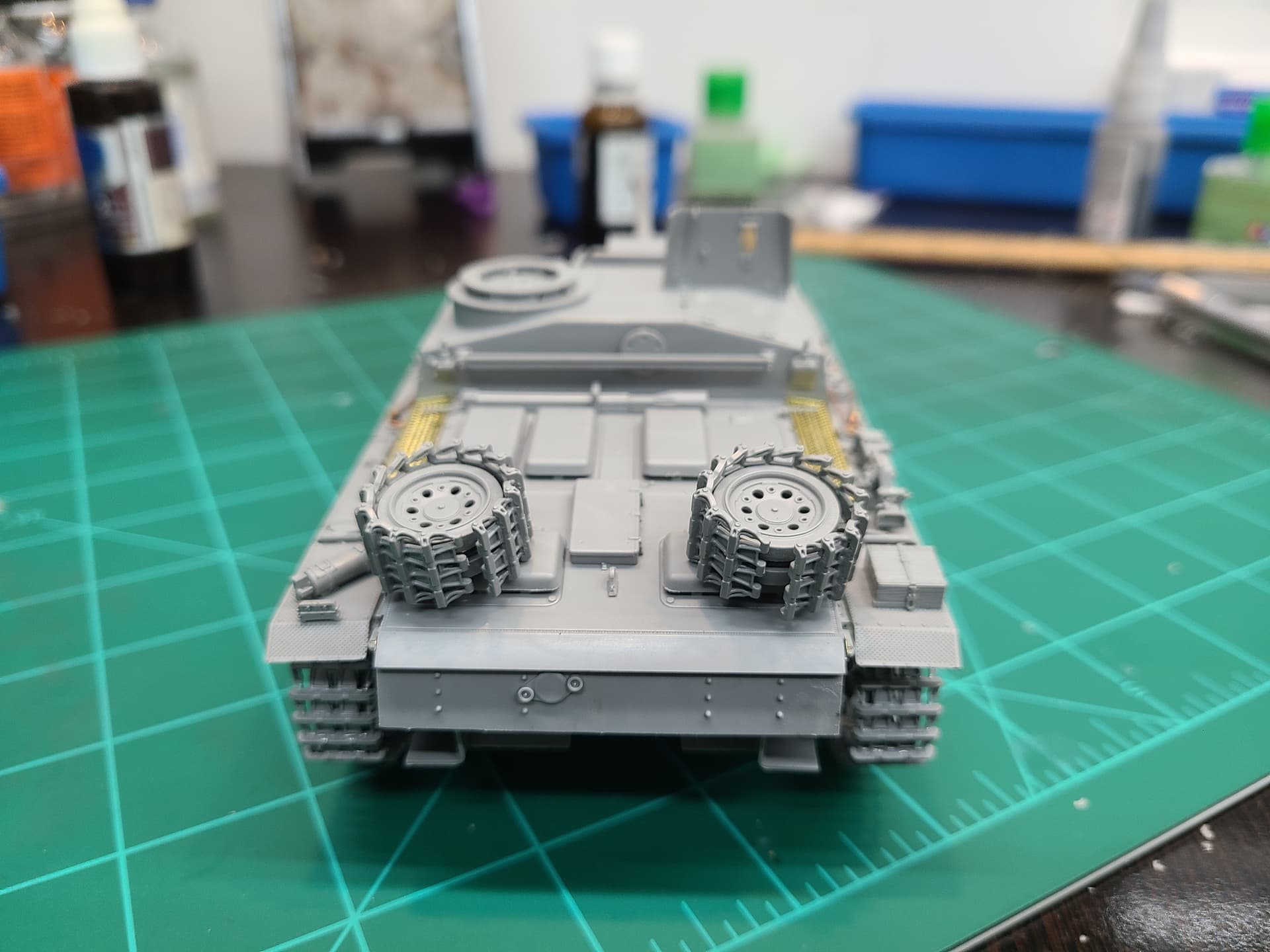
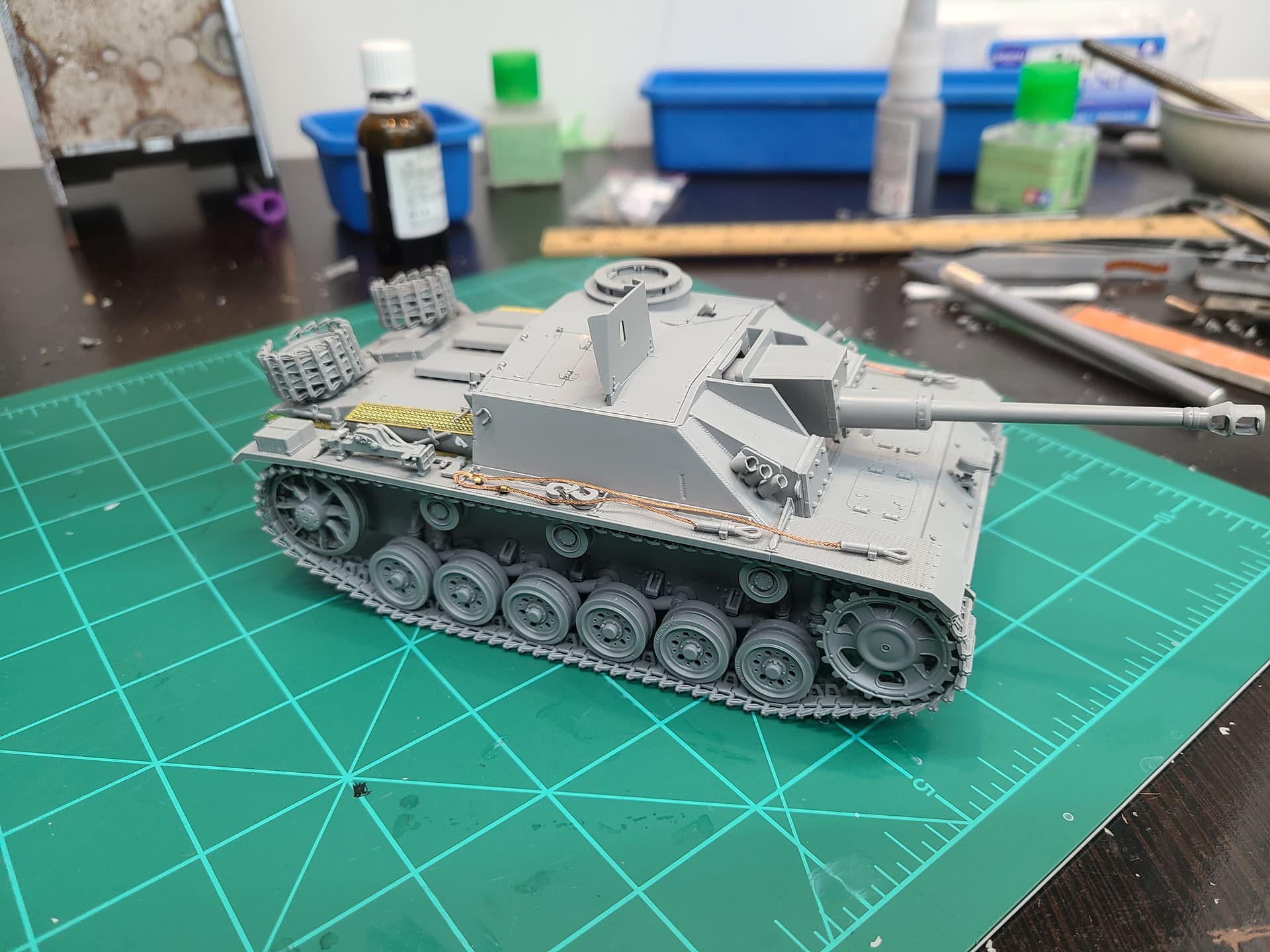
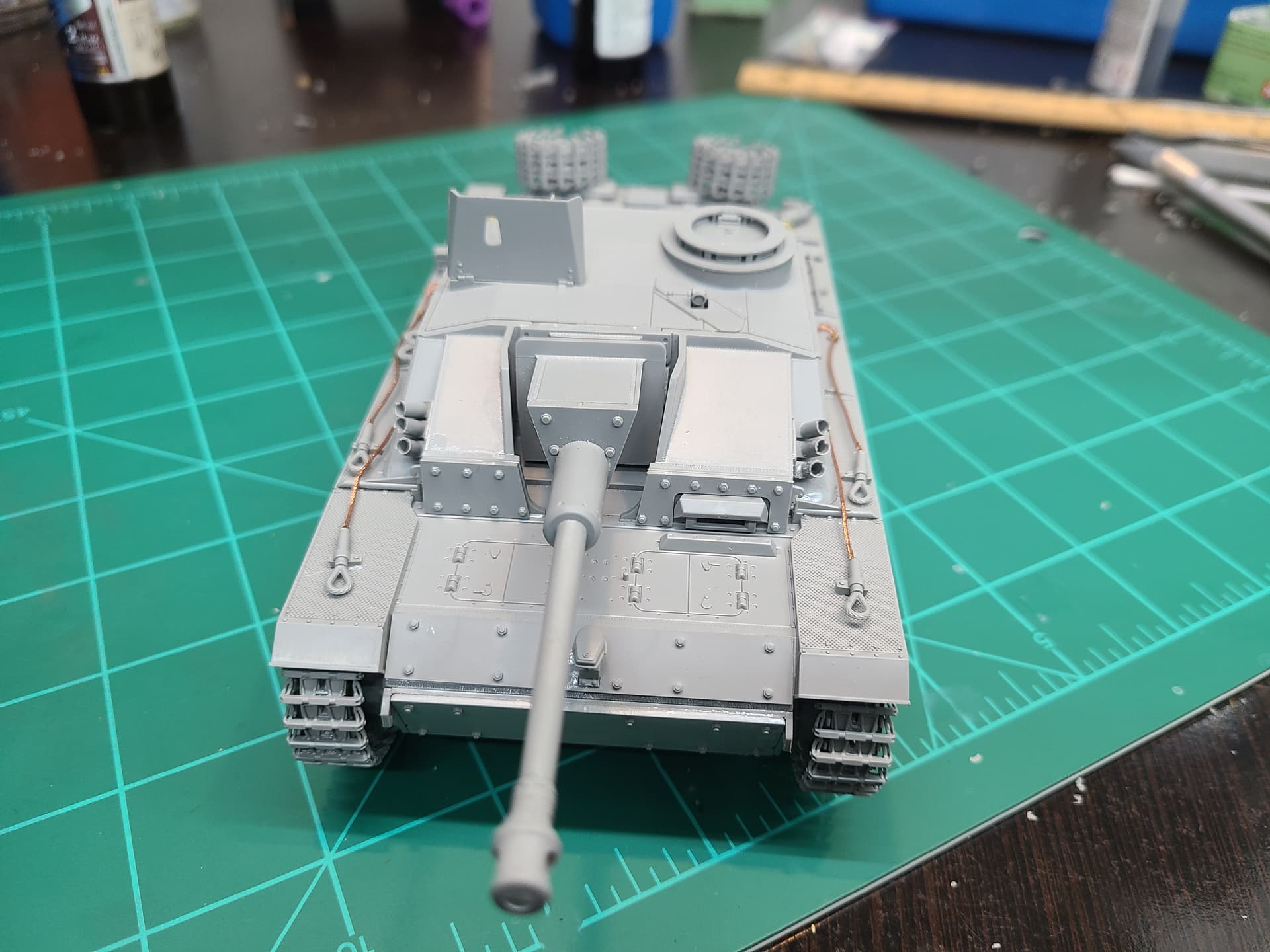
Whew boy. I said I was going to update once I hit a snag or finished step 5, but truth be told I had so many problems I just decided to finish the kit and write the whole thing at once, so here it goes. Photos of the unpainted kit at the end
The complaints im going to make seem bad, and there were a few very rough areas, but all be told ive definitely had worse on other kits. I still compleated the build in 3 evenings, and got a pretty decent Stug out of it. I’ll give this kit an 8/10, there are definitely some problems I’ll address, but its not terrible contrary to how I may make it seem.
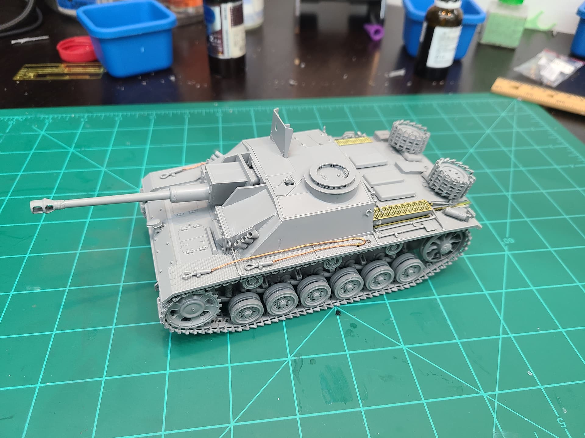
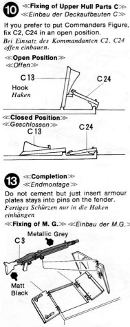
I had previously made comments about mold lines, and oh boy was that an understatement. Every part had some kind of mold line, ejector mark or mold slip where the mold was misaligned. To be fair, ive had worse in kits, but it was disappointing coming from a kit I had expected so much from. Step one has you installing all of the swing arms and suspension componets on the left side of the hull. Some major mold lines were present on the swing arms, and were a pain to clean up especially on the round part that is the joint between the arm itself and the axle. However all but the most forward one will be covered by road wheels, so just clean that one up and the rest just worry about the axle itself. The biggest problem here was the arm stop (part A44) which had a misaligned mold and one whicked mold line. Clean up sucked but it only took a minute a peice. I worred way to much about the gab between the hull and part C17 (C6), but its totally covered by the final drive housing and sprocket, only worry anout filling it if your going to have the sprocket taken off. Step 2 is the same of step 1, just on the right side and gave the same problems. Step 3 is assembling the road wheels, return rollers, idlers and sprockets, plus tow hooks on the back hull. The wheels had a big seam line down the middle, which looked awful but cleaned up in about half a minute each with a sharp hobby knife. The big problem was that the fictional supports that Takom has added around the inside of the wheels for extra, unnecessary support are way too tall. I tried sanding them down, but this was tricky and time consuming, so I just removed them with a cutter and had zero problems with alignment or strength, this was unnecessary and ultimately a waste on Takom’s part. The sprocket had a rare feature in its molding, the sprue attachment points was not on the teeth but the wheel itself, so no short teeth when cutting! Step 4 was the rear hull, exhausts and there housings which all fit well, just a shame I couldn’t leave off the exhausts to paint and weather separately. Step 5 had you add the rear hull plate and its 4 supports, plus a photoetch grill. Unfortunately, the instructions were a bit misleading and you install the grill below and beforethe rest of the part, unlike the on top and after as it suggests. I had to rip the parts off to fix this, and I could have avoided it by studying the instructions more carefully (or if they were more detailed). Step 6 is the track runs, which went together great as expected, however the tracks had bad and noticeable flash and seam lines. Im not going to spend the extra coin or 12 hours on replacement tracks or cleaning these, that would bring me to insanity, so it is what it is. Step 7 is installing the upper hull and the additional armor to the lower hull. I however did this before I did step 6, so installing the tracks was a pain, but that was my fault. I left the running gear and tracks unglued for separate painting, which I’d recommend you do aswell. Step 8 adds the fender supports, tow cables and some tools to the hull. It calls for photoetch clamps to be installed for the tow cables, but is unclear on how to bend them, and the hull has essentially no grip to attach them too on the fenders due to the texture. Due to this, one broke off shorty after and was swallowed by the carpet monster, never to be seen again. Unfortunately (or fortunately) this wasn’t a problem because the metal cable for the tow cables provided was too short (by probably an inch?) And I was unable to make the second cable reach the spot where the photoetch clamp had gone missing. I guess two wrongs do make a right(ish) in this case. Step 9 adds the tools to the left rear hull, the air intake and some rear covers. There is essentially no place to secure photoetch part 6 onto, so I had to fiddle with it and a lot of superglue, not fun. Additionally, PE part 8, which is the cover for the air intake on the left has very little area to be glued to in some parts, and if you dont have the casmate attached to allign it properly, it will most likely be glued on too far one way do to the lack of mounting points. I didnt have this problem because I skipped forward and installed the casmate early, but I’d definitely be careful here. Step 10 is more rear hull parts, the most notable being a PE bracket for the the bolt cutters that not only lacks a a clear place to mount it, but it lacks the necessary engraving to be bend as instructed. I’d bet money this is because they only printed one side of the etch, a problem the pops up again. Step 11 is essentially the same of 9, but on the right with a few differences. The problem with the PE mesh on the intake is again present, but the big one is that TP7 is completely incorrect. They gave you the same part as TP6, but because the part is supposed to have a texture on it, it must face a certain way. Unfortunately it also has an angle on one end, so you either place it with the texture the right way with the angle on the wrong end, of the angle correct with the texture missing. I cut of the angle on the incorrect end, and cut a new one on correct end. This ended up shortening the part a bit, but the jack hides this a mostly, and its hard to notice. Its a simple oversight, they duplicated the part rather than mirroring it, but its crazy that they somehow didnt notice this durring test building. Step 12 is building the jack, which is fiddley but come out nice, and the spare road wheel holders on the engine deck. I wouldn’t glue the wheels in place, so you cane paint them separately. I added some of the extra track links around the wheels, which looks real nice, and realistic. Steps 13 and 14 add the smoke lanuchers and front plates to the casmate, along with some small sheilds and handles. Step 15 makes the gun craddle assembly, but unfortunately none of the round parts in the gun assembly fit. Parts N27 and N28 have a hole that is too small to fit the gun assembly, I enlarged them by running a hobby knife around the inside edges, if your careful its an easy fix. Also, part N34 here didnt want to stay in place, and it ended up a little lopsidded, but its hard to notice. Making the gun sheild was terrible, part N2 didnt fit into N21, and I had to widden N21 similarly to N27-28. It didnt glue in exactly right and left a small gap on the bottom, but its to small to notice after paint (hopefully). Step 16 is adding parts to the rear of the casmate, which fit well but are shown in the completely wrong order. Seriously face-palmed here, this was embarrassing on Takom’s part. You also assmeble the muzzle brake and barrel at attach them to the sheild. The brake is decent, but the parts seem to have some sizing problems, so youll probably need to sand or remove some plastic around the front baffel. By this point I had already completed the build out of order, so here is where I did my final assembly, but ill follow the proper instructions. Step 17 mates the gun and its sheild to the craddle and mount, but this was completely wrong. Its simple, but none of the locating pins on on the craddel fit into there respective holes on the sheild(it was honestly embarrassing, there is no excuse here) I just cut them off and was careful with gluing them in place, a shame but easy enough to fix. However it did end up drying a little sideways, its hard to detect but from the top its ever so slightly crooked. Step 18 had you assemble the roof, and I chose to keep the hatches closed. Its important to decide here if you eant the comanders hatch open or closed, because its almost impossible to glue it closed after the next step. Id also choose here whether or not you want to have the periscope hatch for the comander open or closed, its much easier to glue it with the hatch separate. The periscope itself is pretty nifty, but the mold lines were a pain to clean off and I ended up not using it. (In hindsight I regret that) The instructions were unclear on how exactly to install the periscopes, but with some looking and thinking I got it figured out alright. Step 19 has you add the top ring for the comanders cupola, the mg 34 and its sheild, and install the roof on the casemate, completing the build. The provided MG is decent at least for a kit of this quality, but its definitely lacking. No ammo box or drum is provided and I couldn’t stand how it looked without one, so I left it off of my build. Normally I would have grabbed something aftermarket from the stash, but I decided to keep the kit completely out of the box, and it look just fine the way it is.
Ultimately the kit is pretty decent despite the problems I pointed out. It seems that all of the parts that are universal with all of Takom’s Panzer 3s were great aside from mold seams (probably due to a worn out mold) but the parts that were specific to this variant was quite poor, with most of the gun componets just not fitting at all. Still, with a little bit of work you can fix this and it turns out just fine. I would absolutely recommend this kit for beginners, if it wasn’t for the photoetch. Im not terribly experienced myself, and I struggled, its has some problems that may turn off a first timer. But besides that its a decent kit for a moderately experienced builder, and probably a kit I’ll build again, even if its just to teach my little brother. Next up is painting, still not sure what scheme I’ll go for, but I’ll post here when im done. Till then, good building and happy landings,
Bo
(P.S. dont mind the missfitting of the tracks and such, they are loose for removal and later painting, not a kit problem )