Takom 1:35 AH-64D Apache State-to-Finish Build

Worked today… well… sort of… spent half the time searching for a part. More about that later.

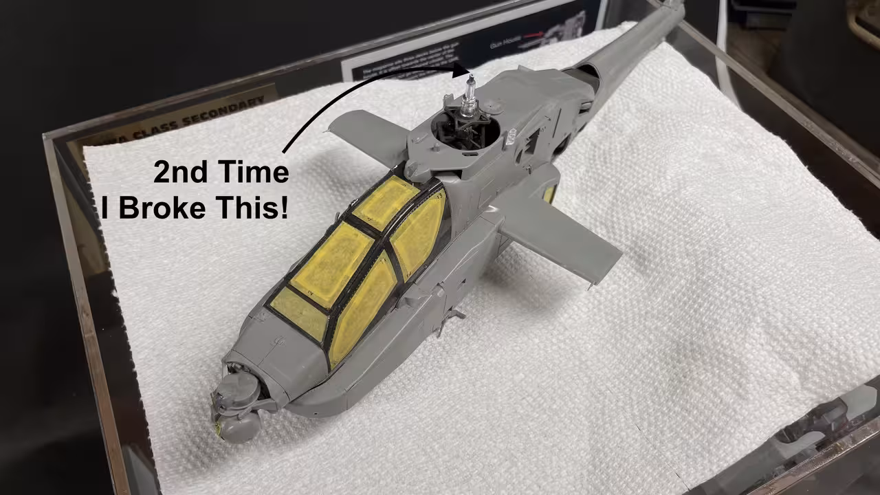
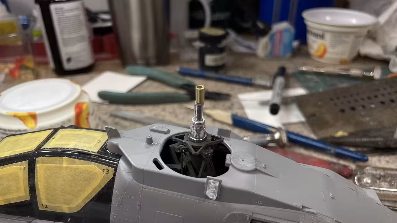
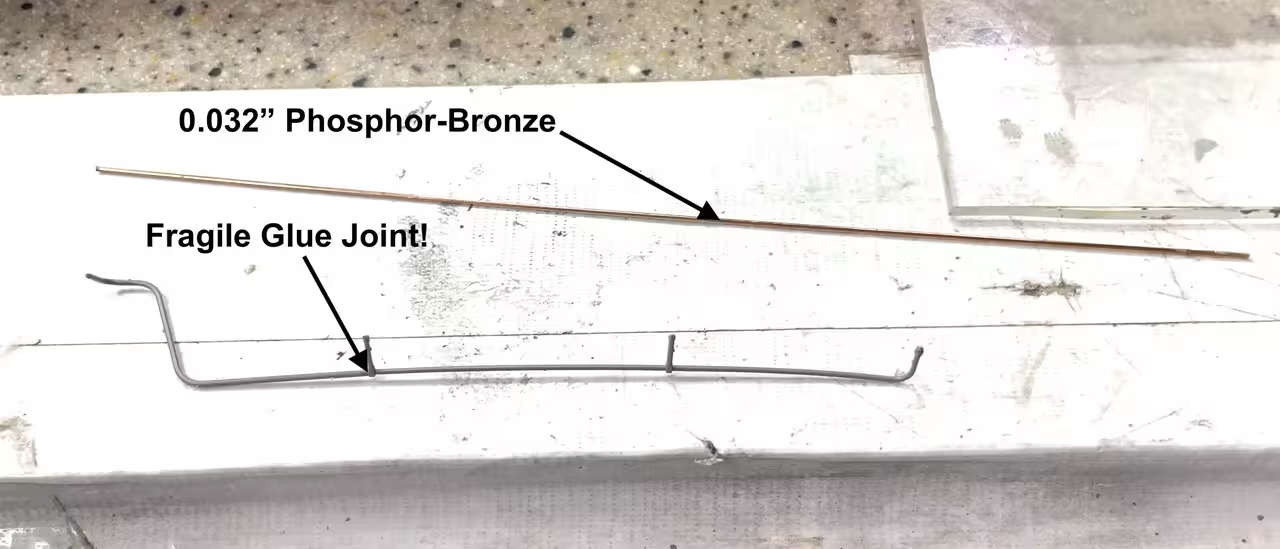
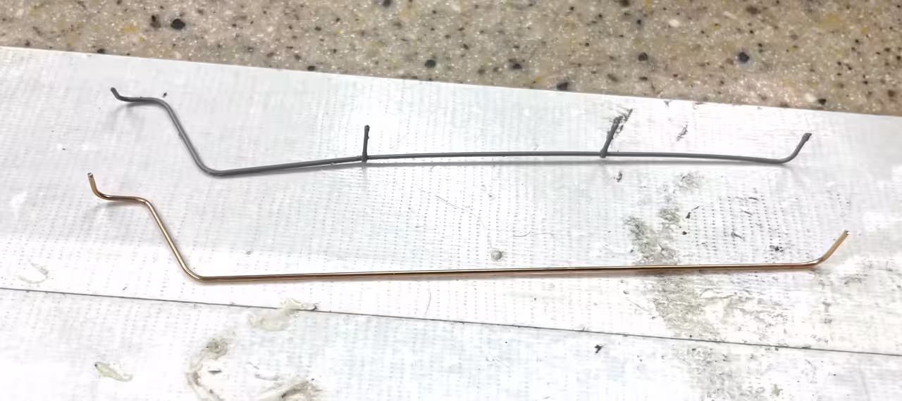
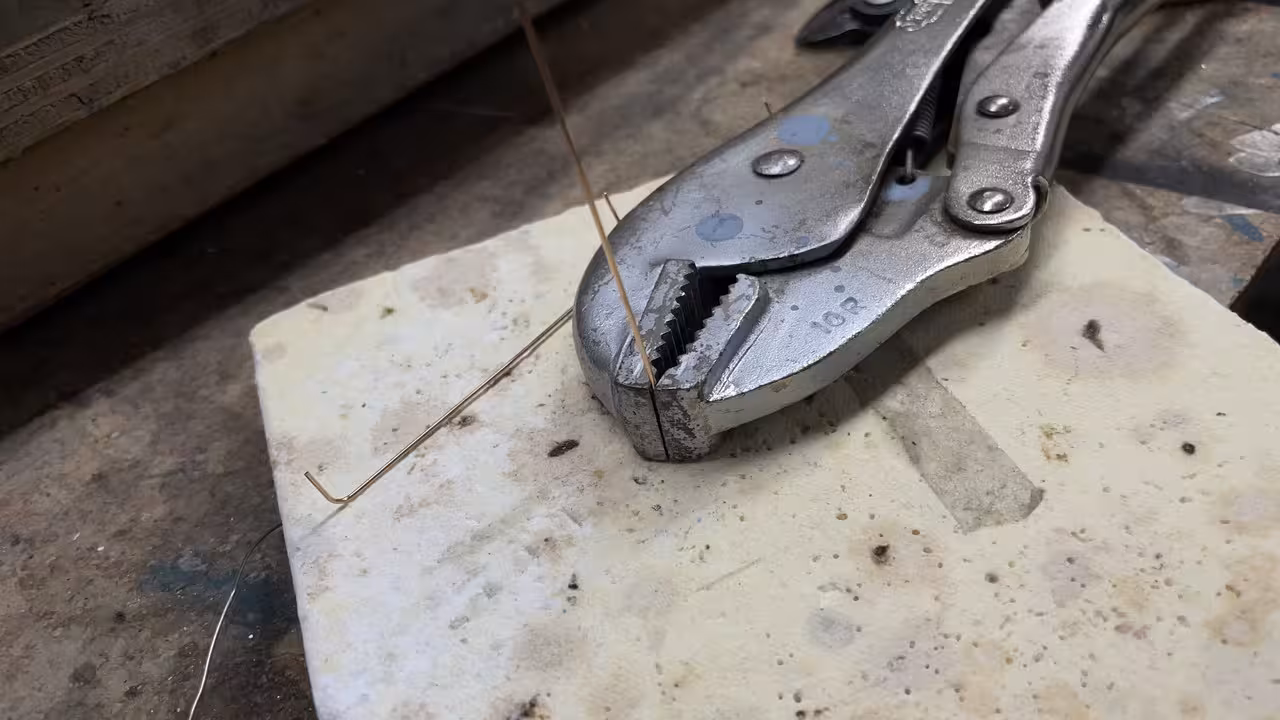
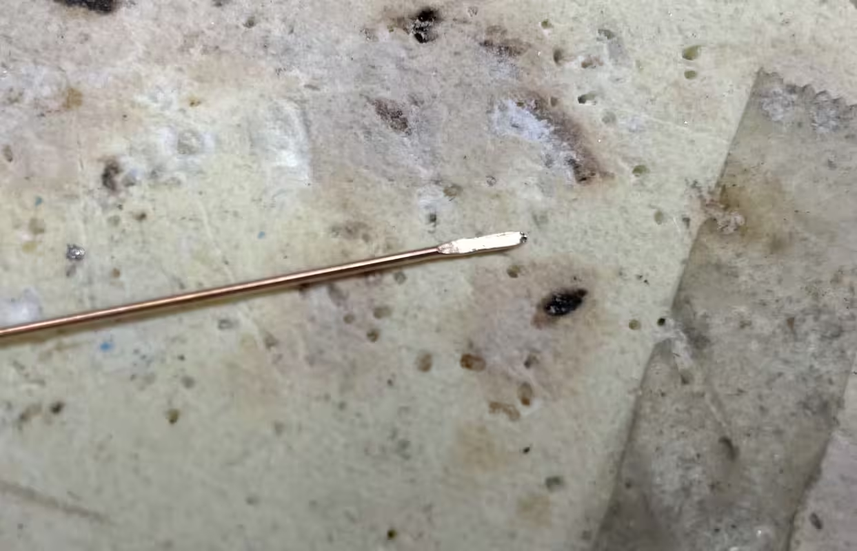
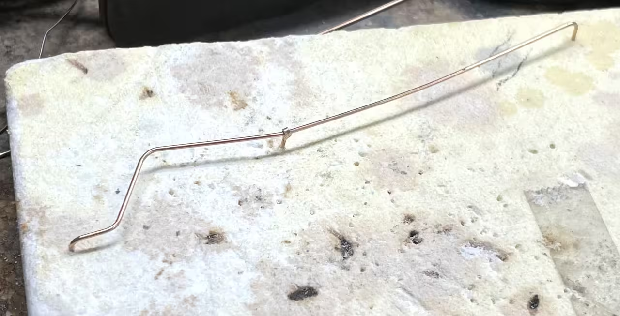
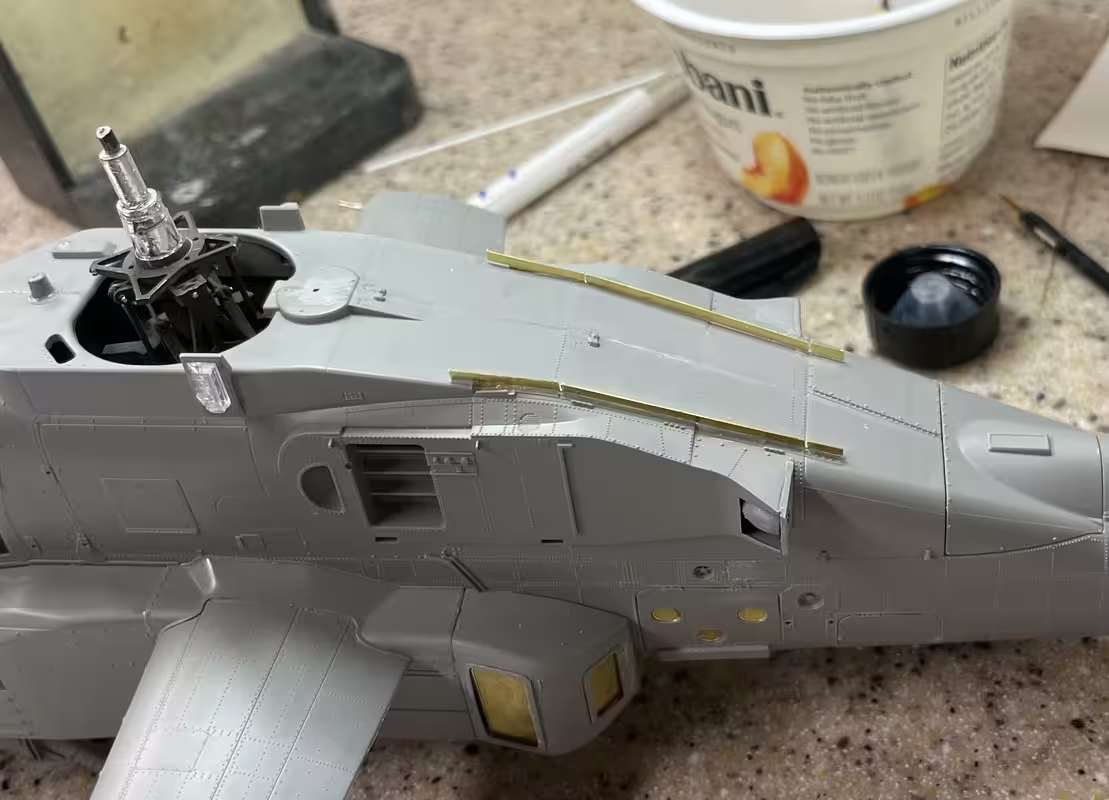
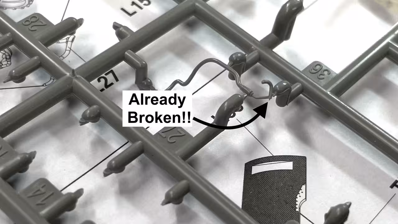
Got some smalll details put on the roof and proceeded to damage the small vertical antenna. So I cut it off and will replace it with music wire later on. The other detail also got whacked, but survived.

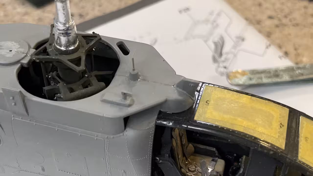
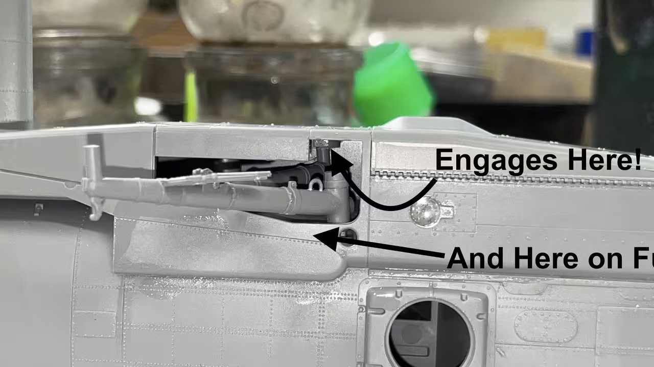
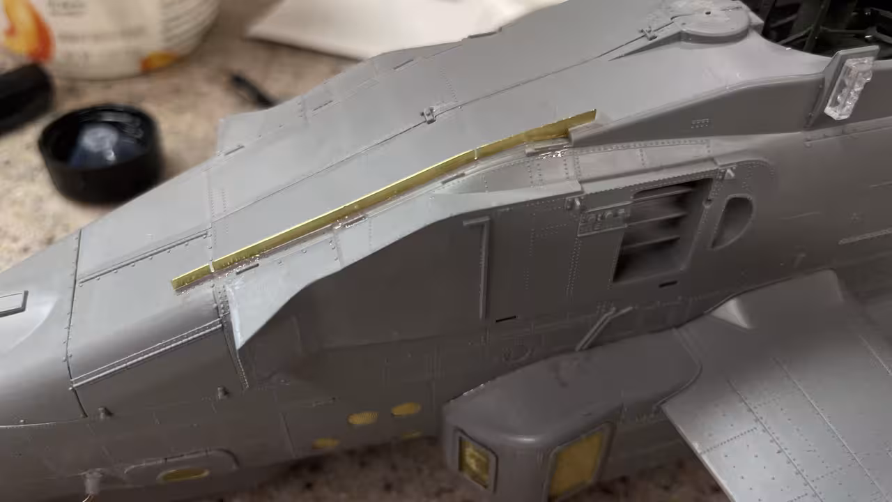
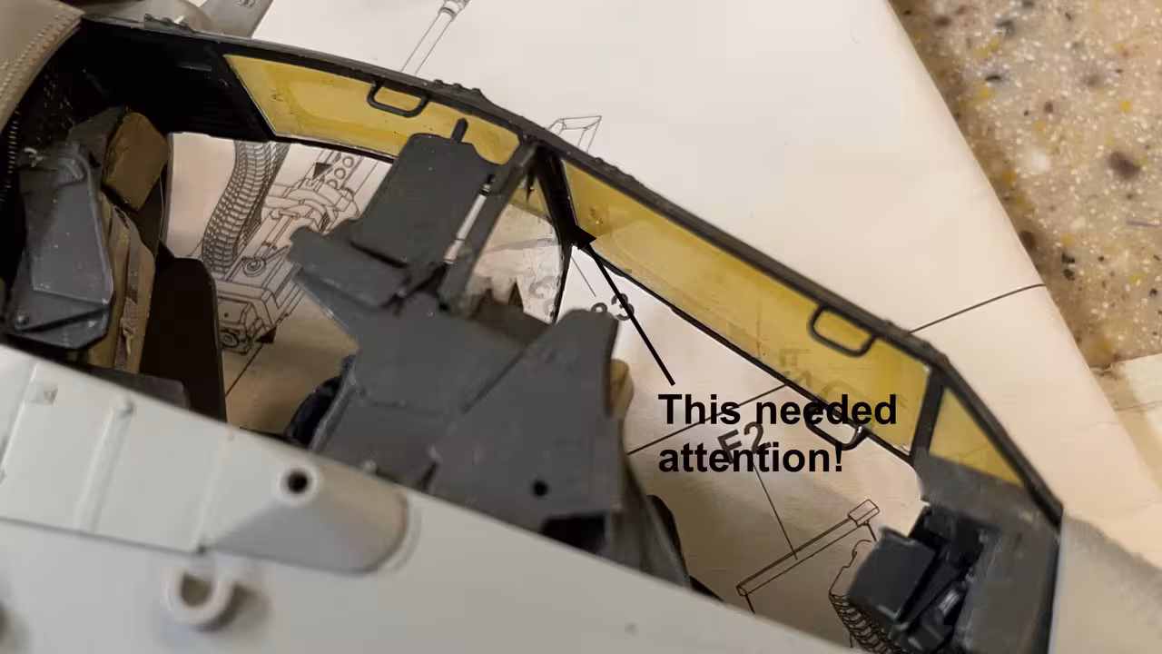
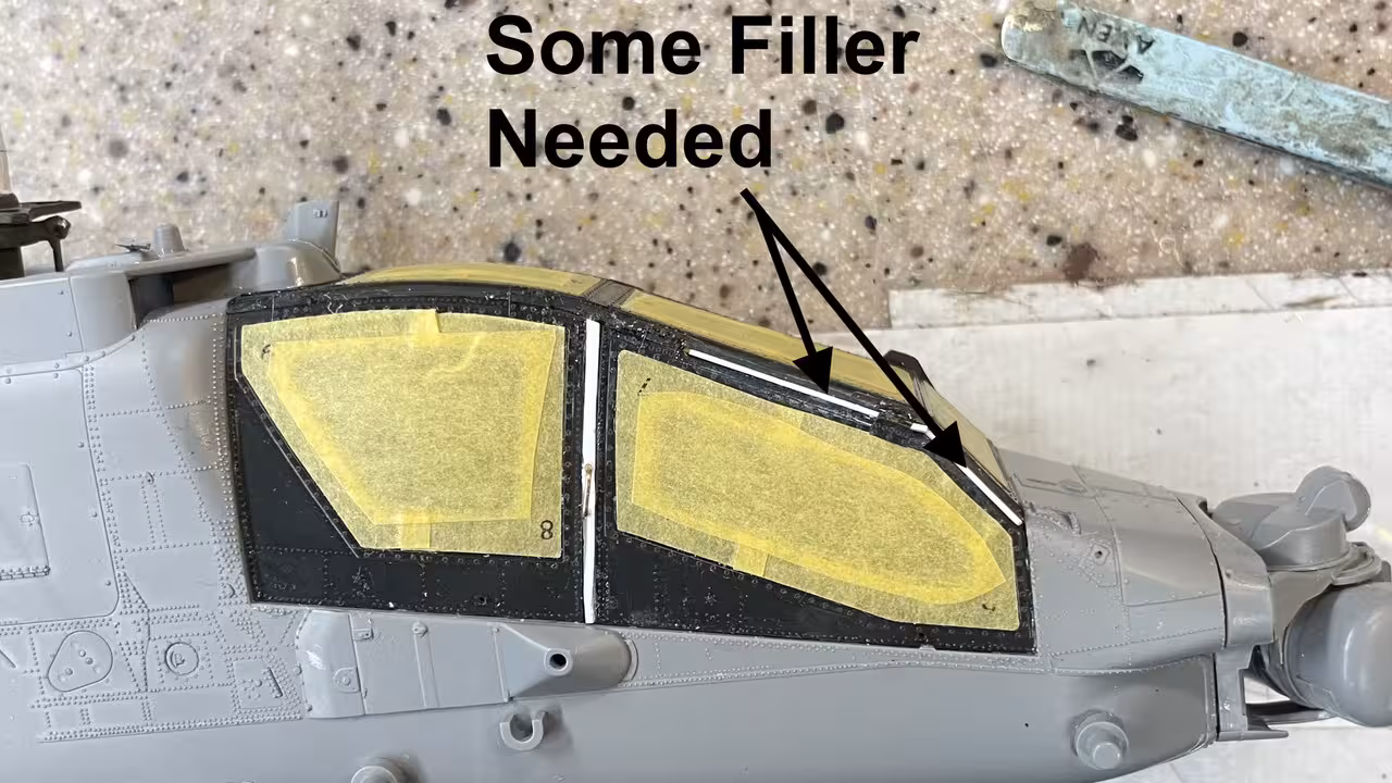
With the top roof’s handles secure, I glued it in with Tamiya liquid. Front and back went in nicely. There part over the mid-tub armor panel was gapped and needed some special attention.

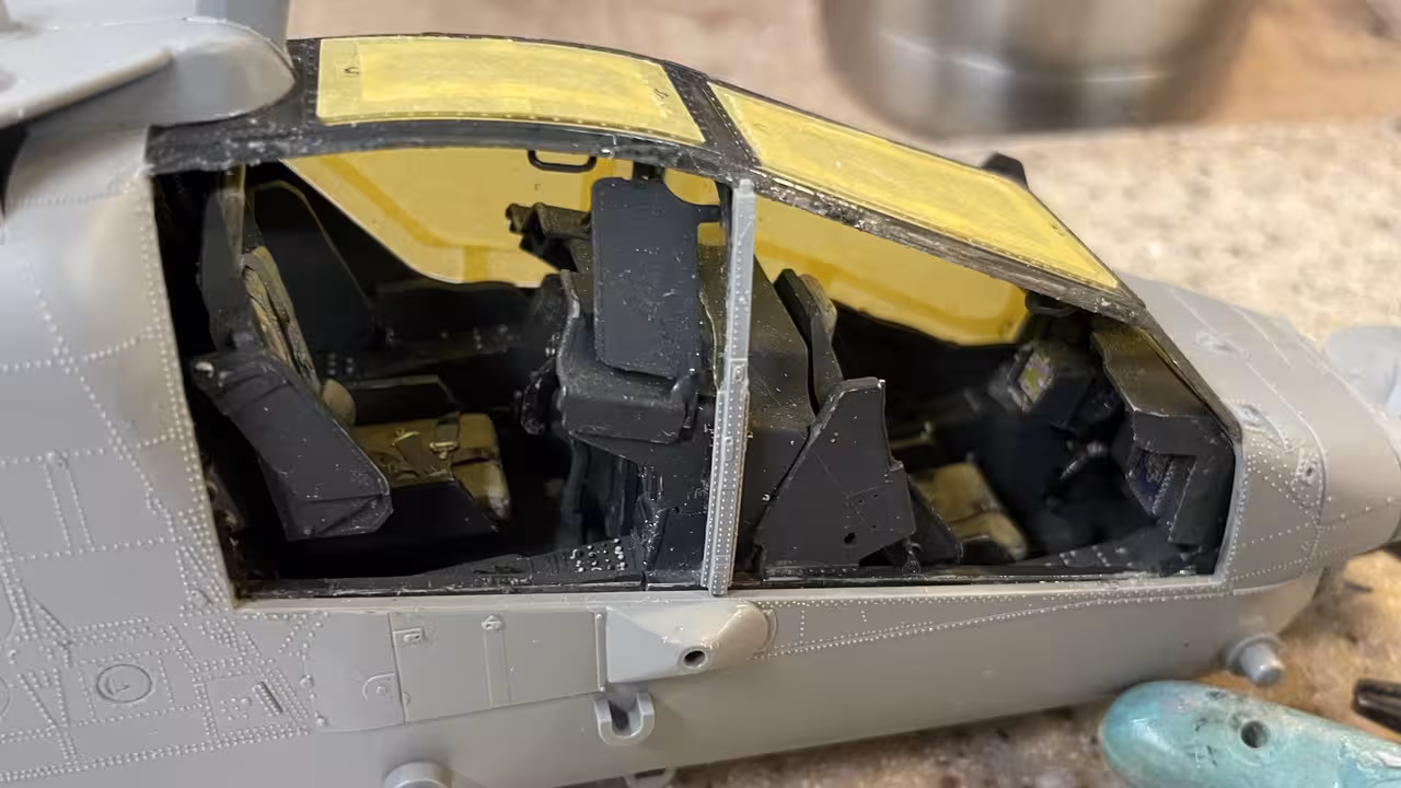
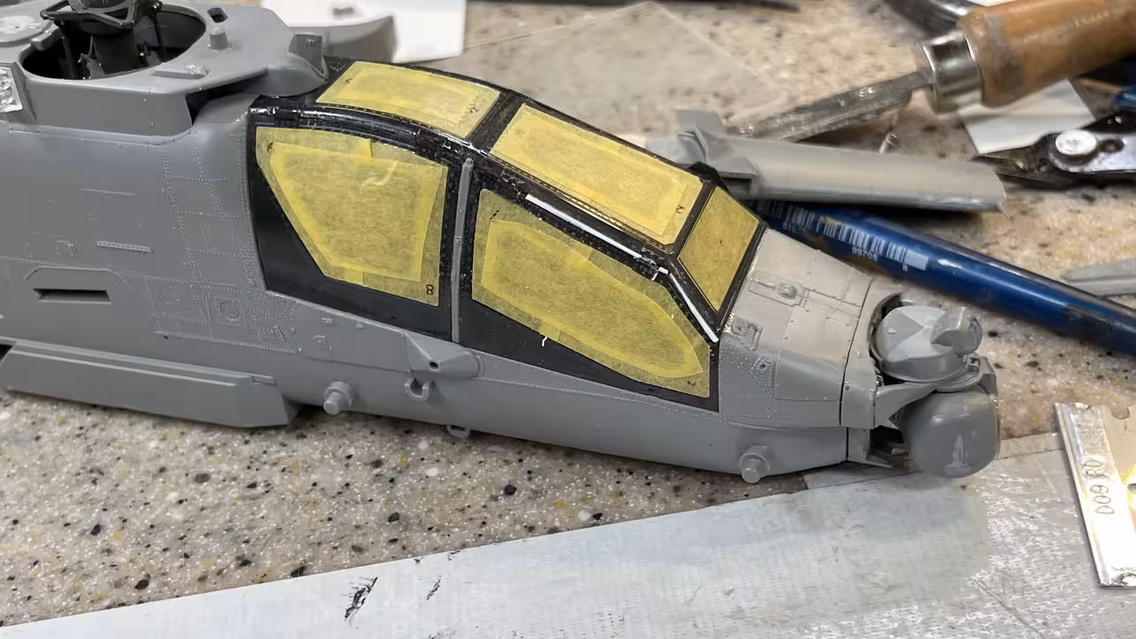
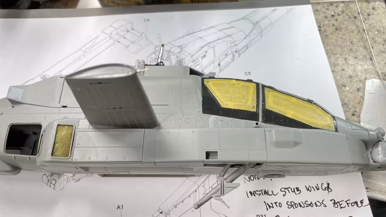
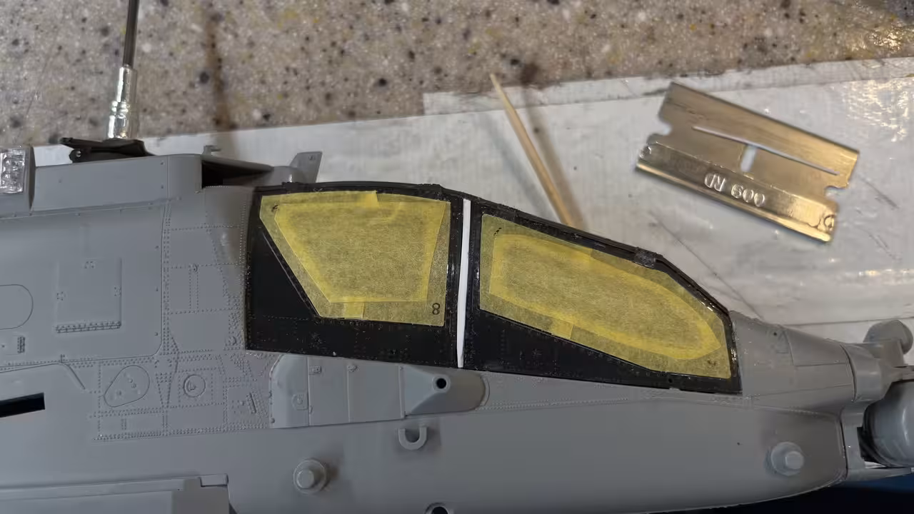
I glued in the pilot side glazing using Testor’s Canopy Cement. I like that stuff since it does hold reasonably well, can clean up easily, doesn’t craze and, G_d forbid, you have to remove the part, you can. Today I did. A couple of pieces of tape held it in place until it cured.

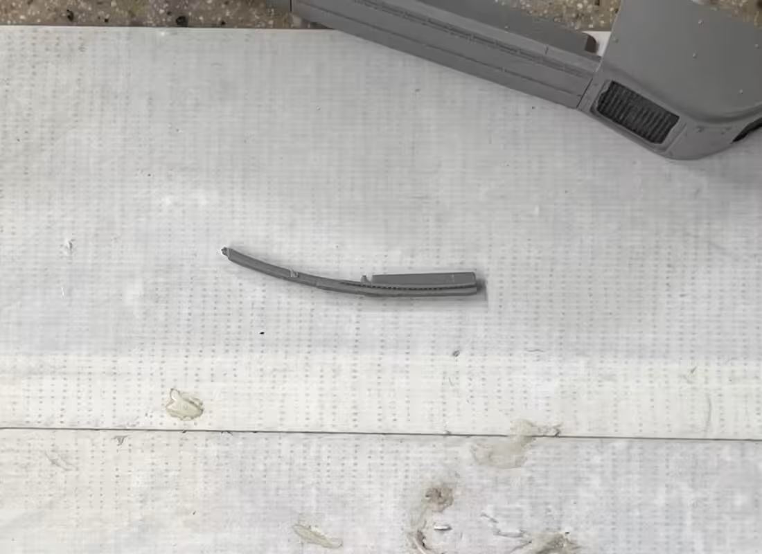
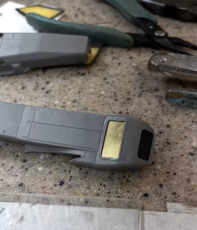
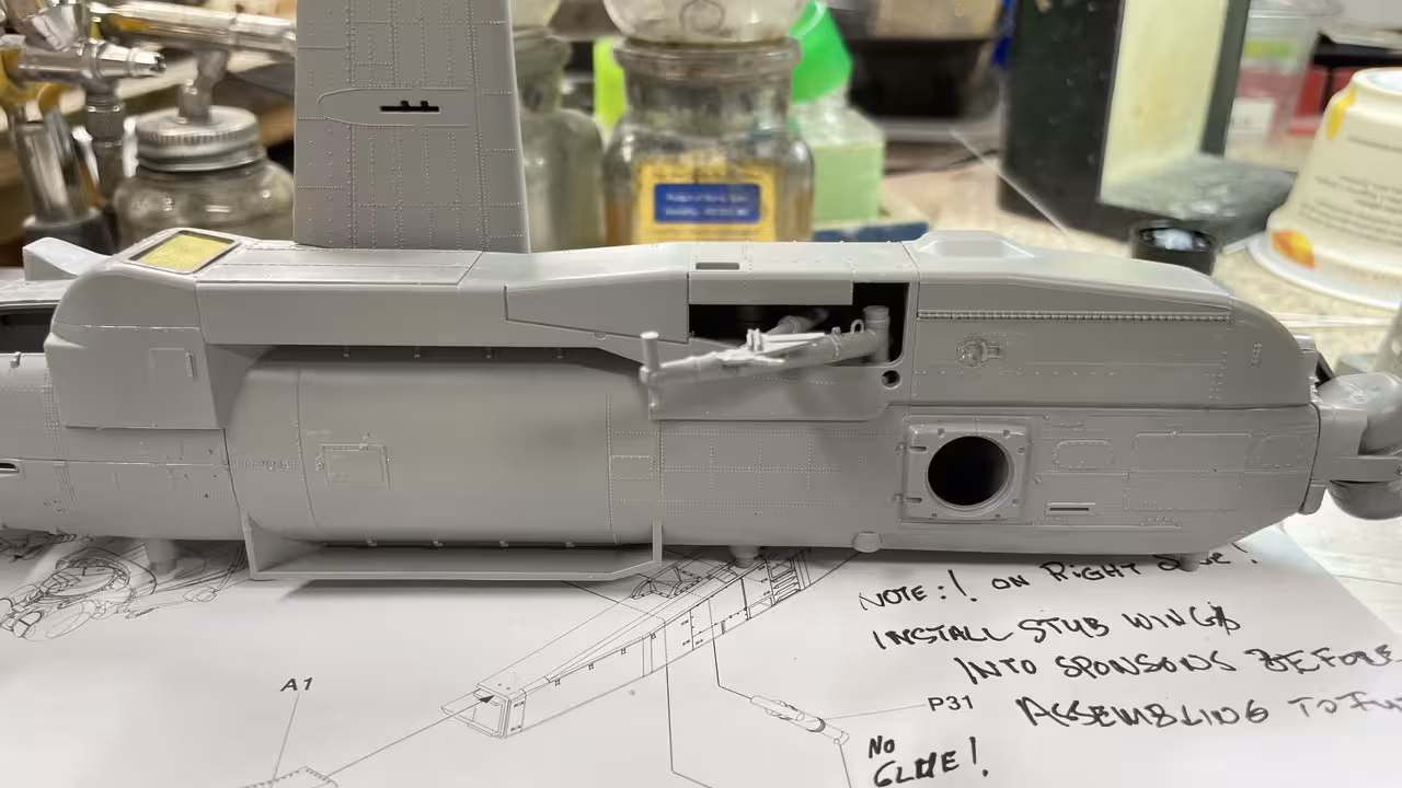
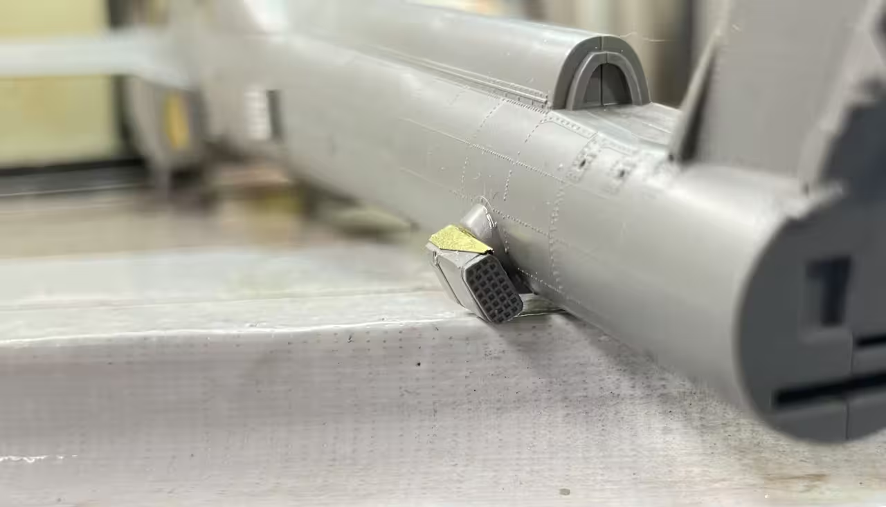
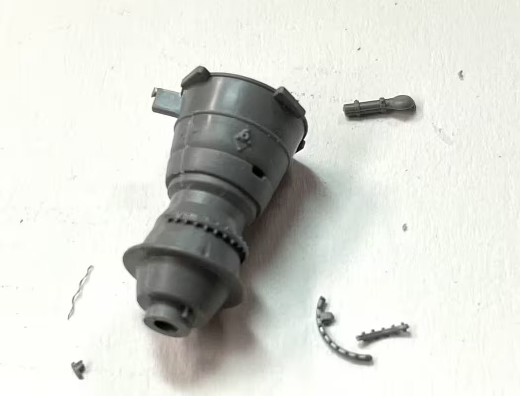
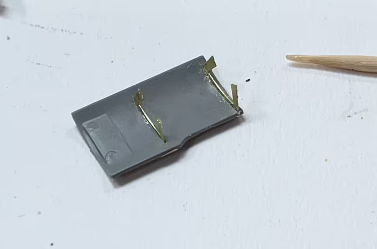
The Strb’d side needed Part P53. It’s specifically shaped filler piece that goes in between the moveable frames and has provision for a hand grab. I cut off one end, and when the other end cut… whoosh! Gone! It took off to the left in an elevated trajectory. I didn’t expect this part to be a flyer. I didn’t hear it land anywhere. I usually try and listen if a part hits anything.

I cleaned and emptied EVERYTHING. I checked my clothing, shoes, etc. I emptied a chaotic box of scrap wood and junk under the workbench (it needed it anyway… badly), swept everywhere, checked every nook and cranny of my other main workbench. This puppy was in the multi-verse.

So I fabbed a filler piece and glued it in. It lacked the surface details of the real thing, but did the job. It wasn’t as easily as it looked since the slot was not uniform width all the way down.

There was also some gapping at the top of the front glazing and I filled this with styrene to be trimmed later.

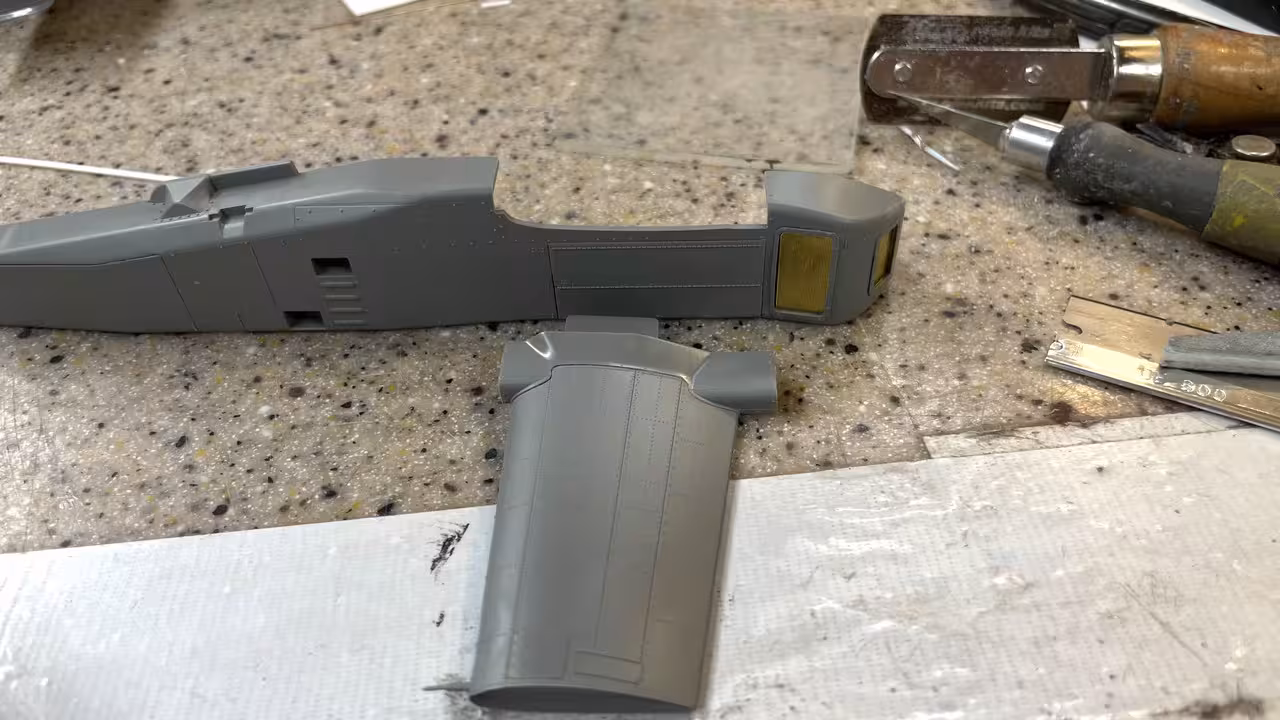
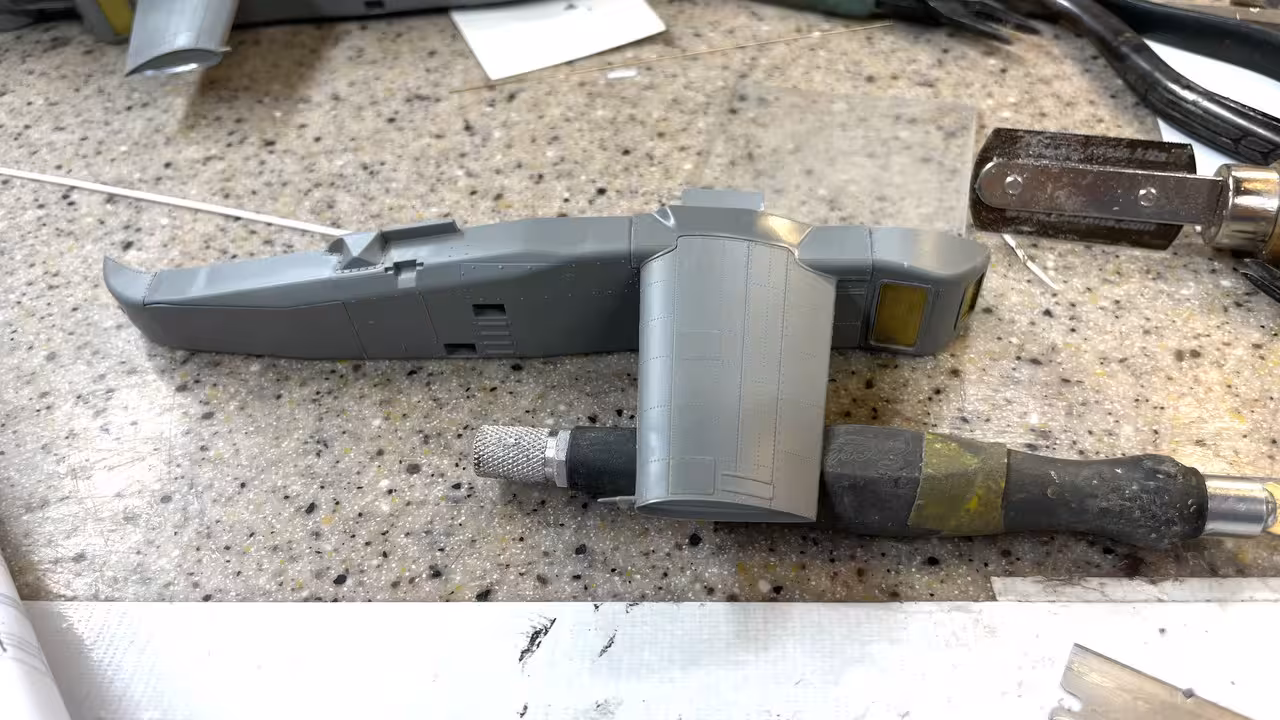
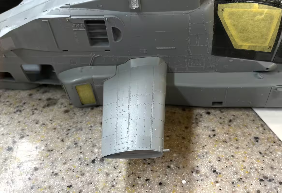
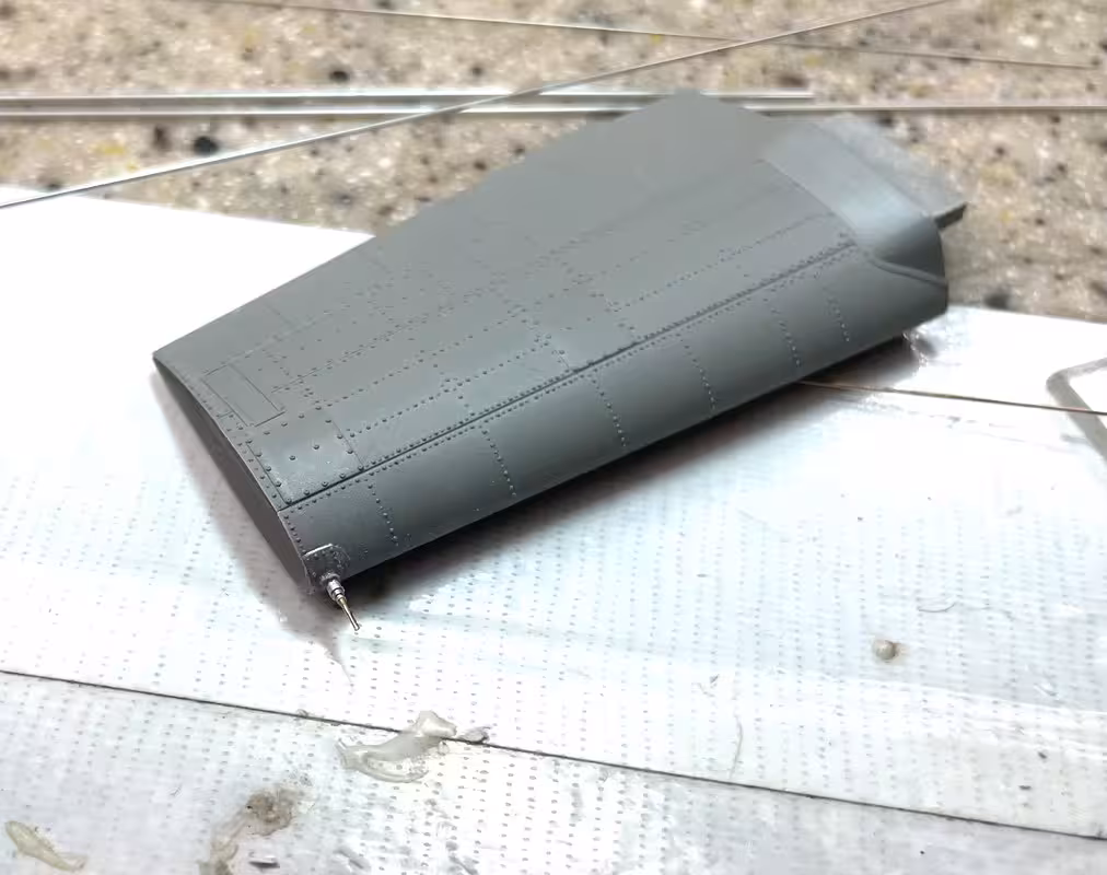
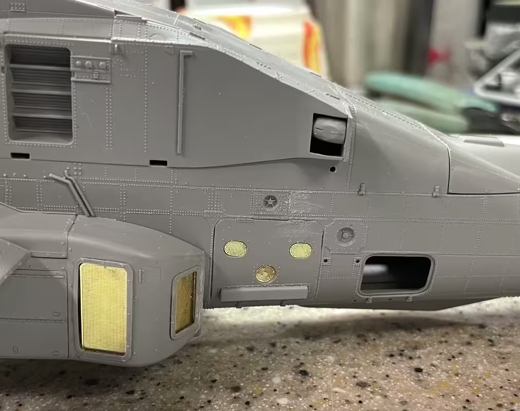
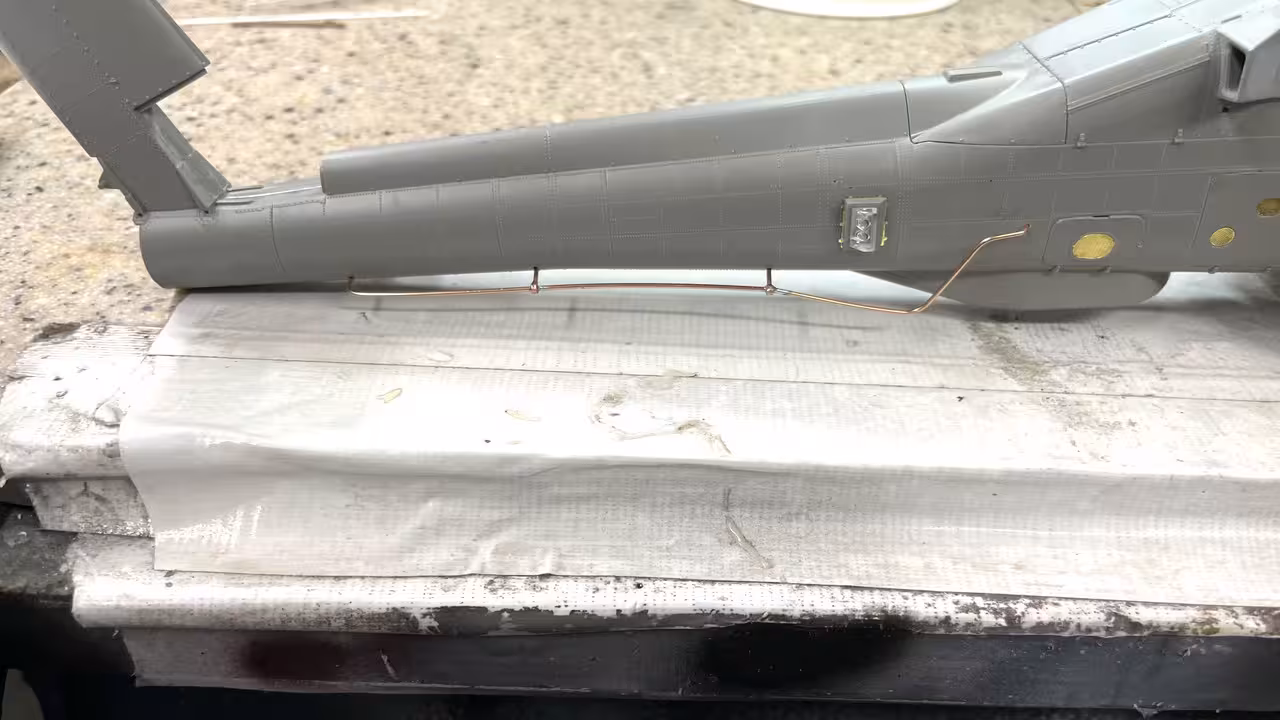
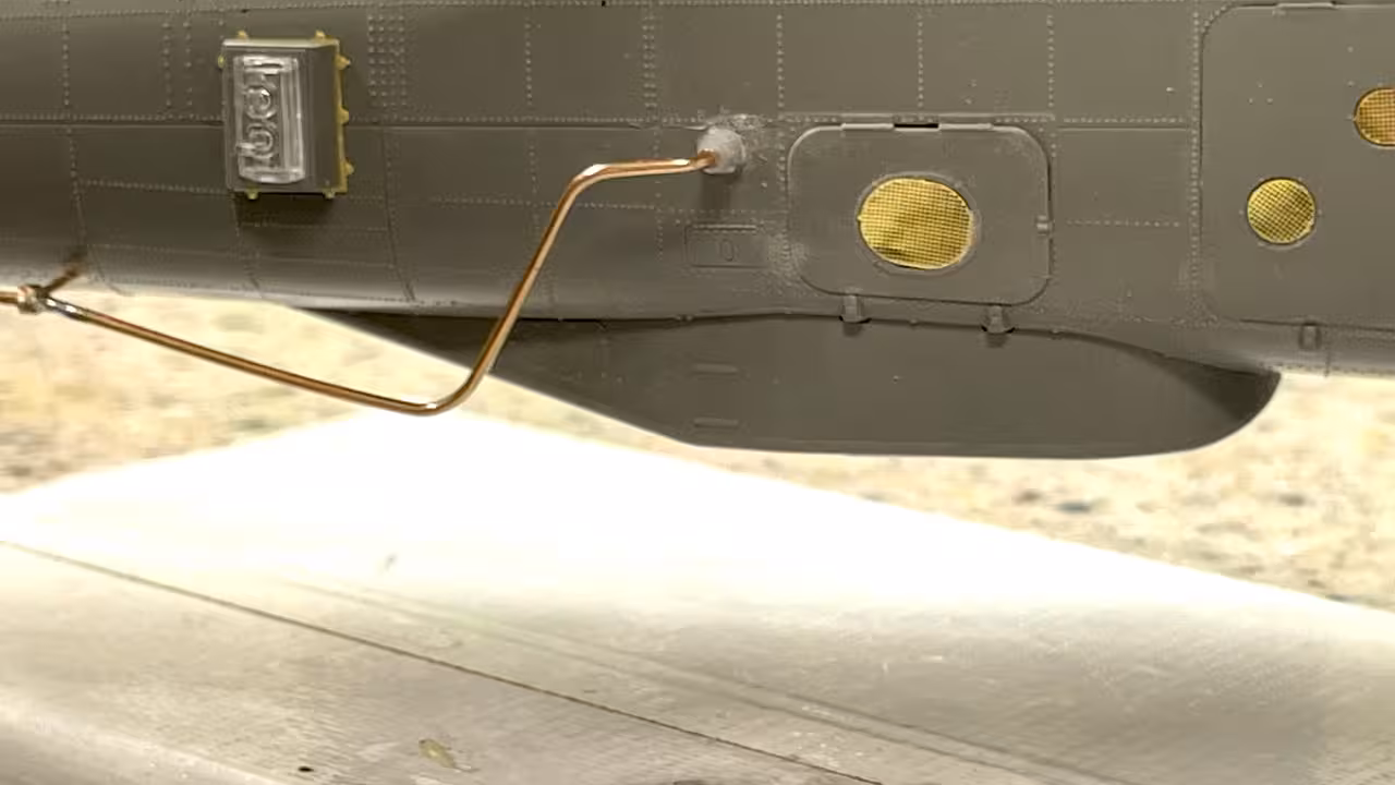
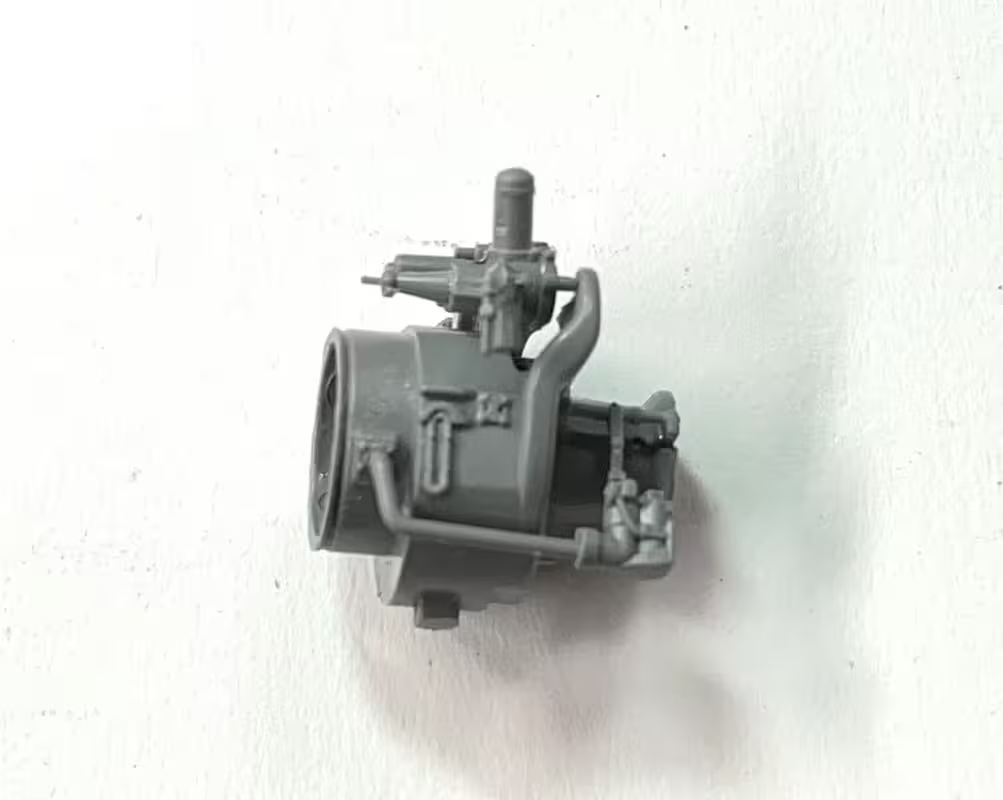
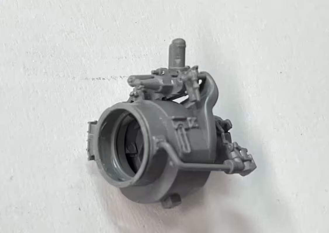
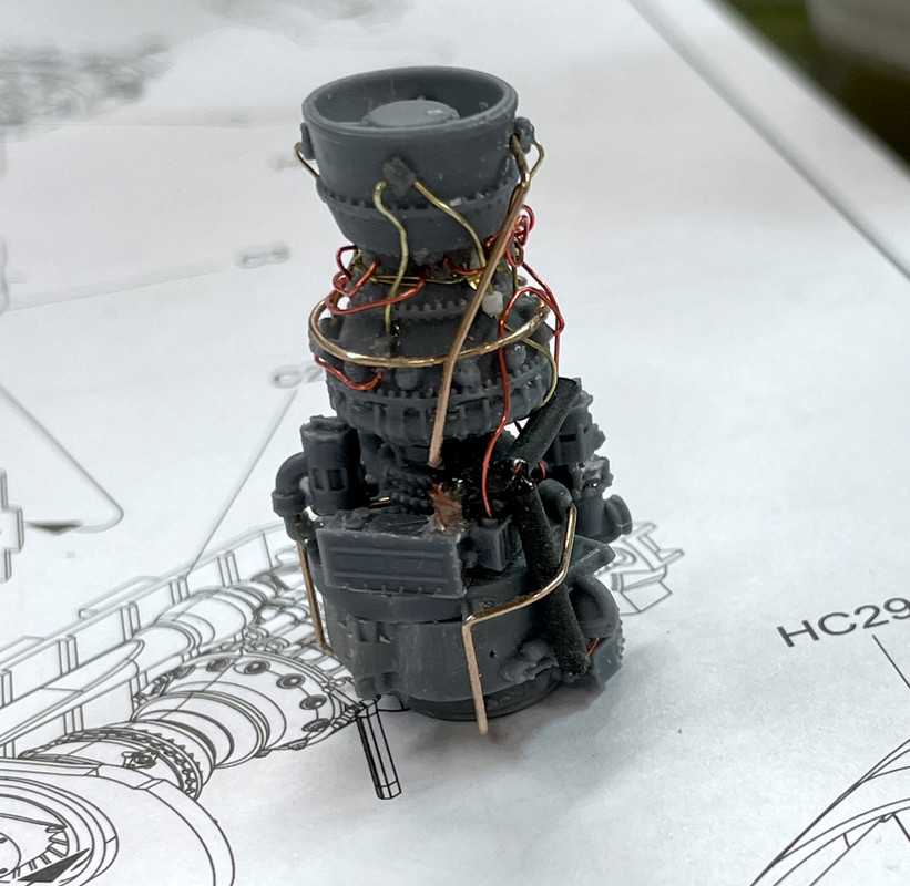
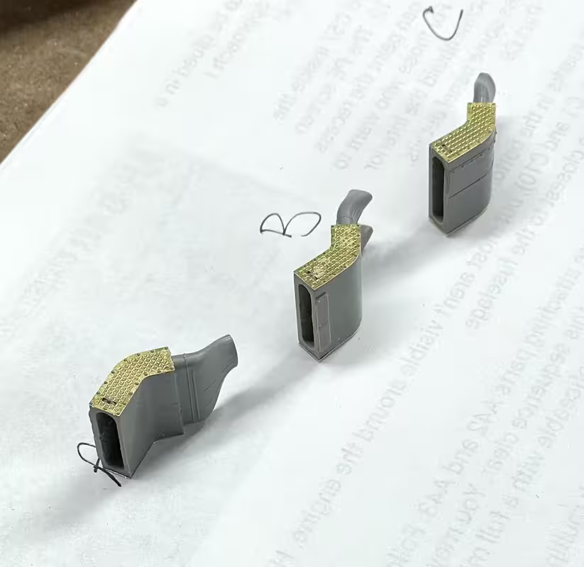
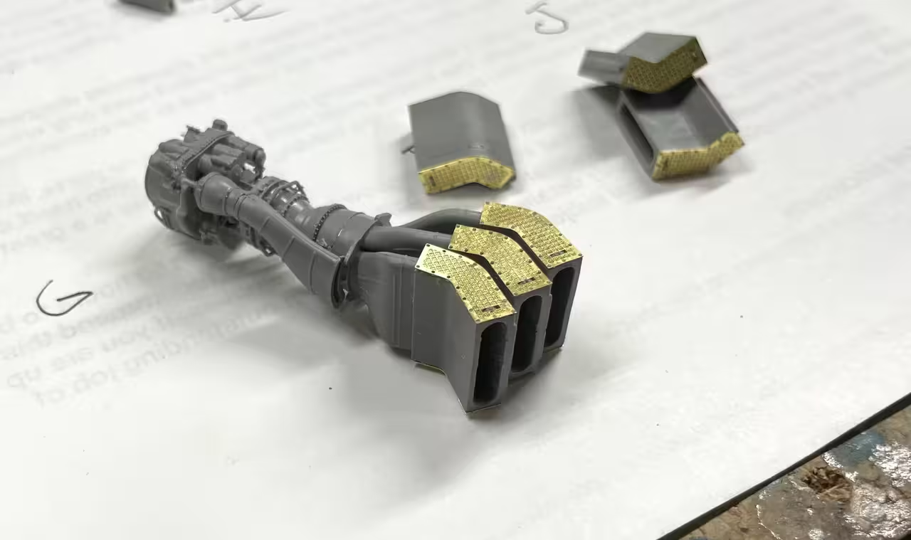
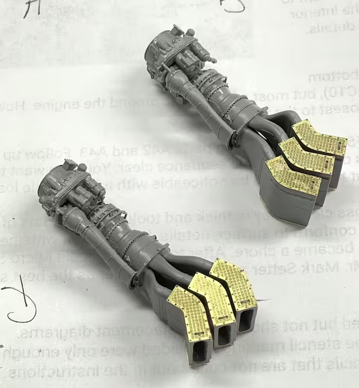
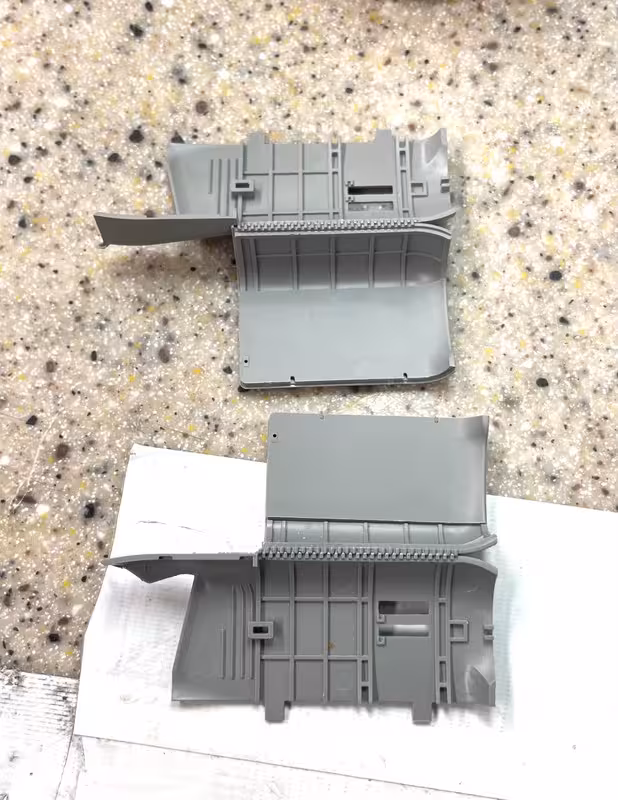
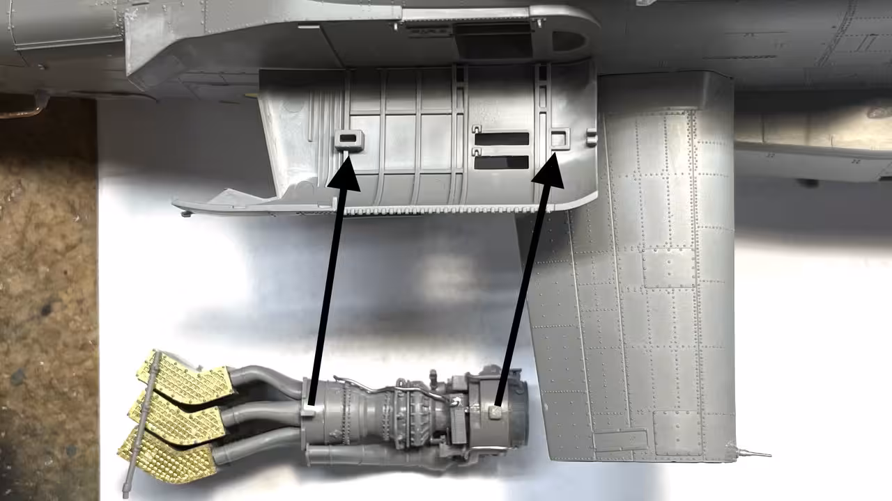
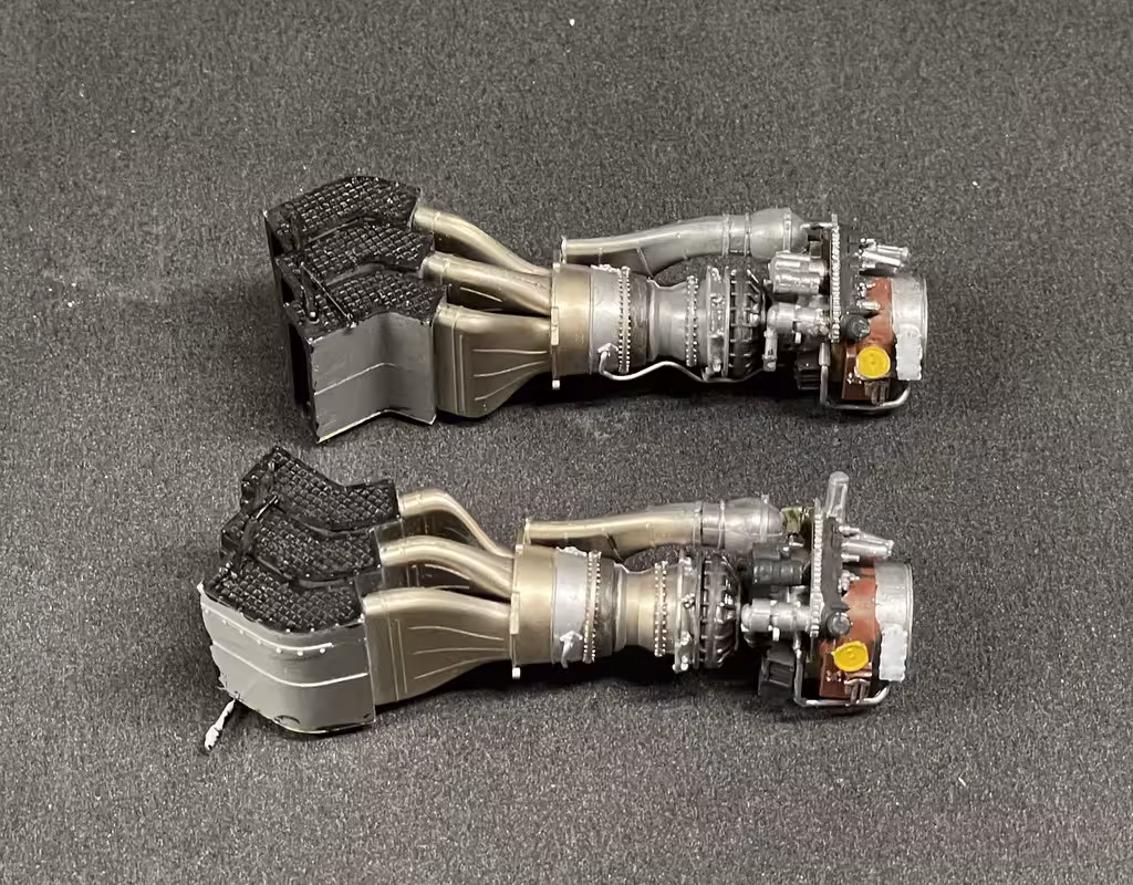
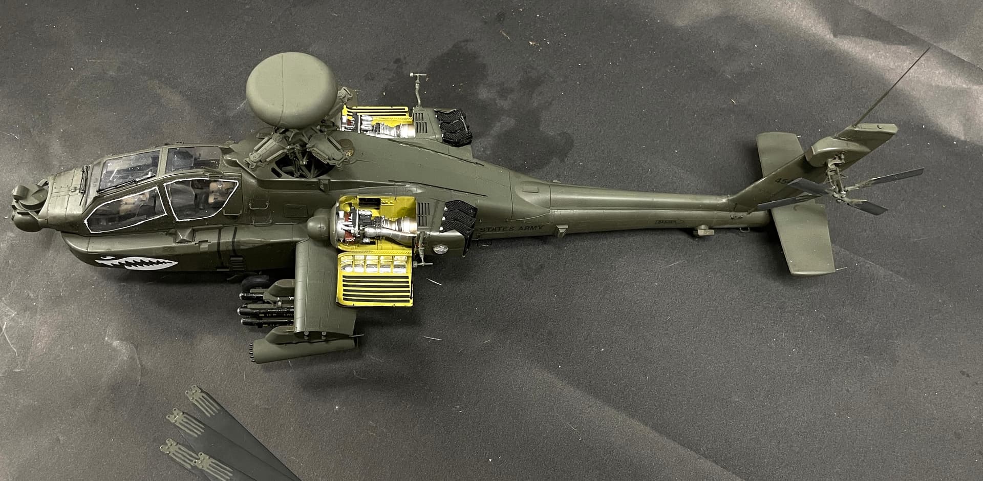
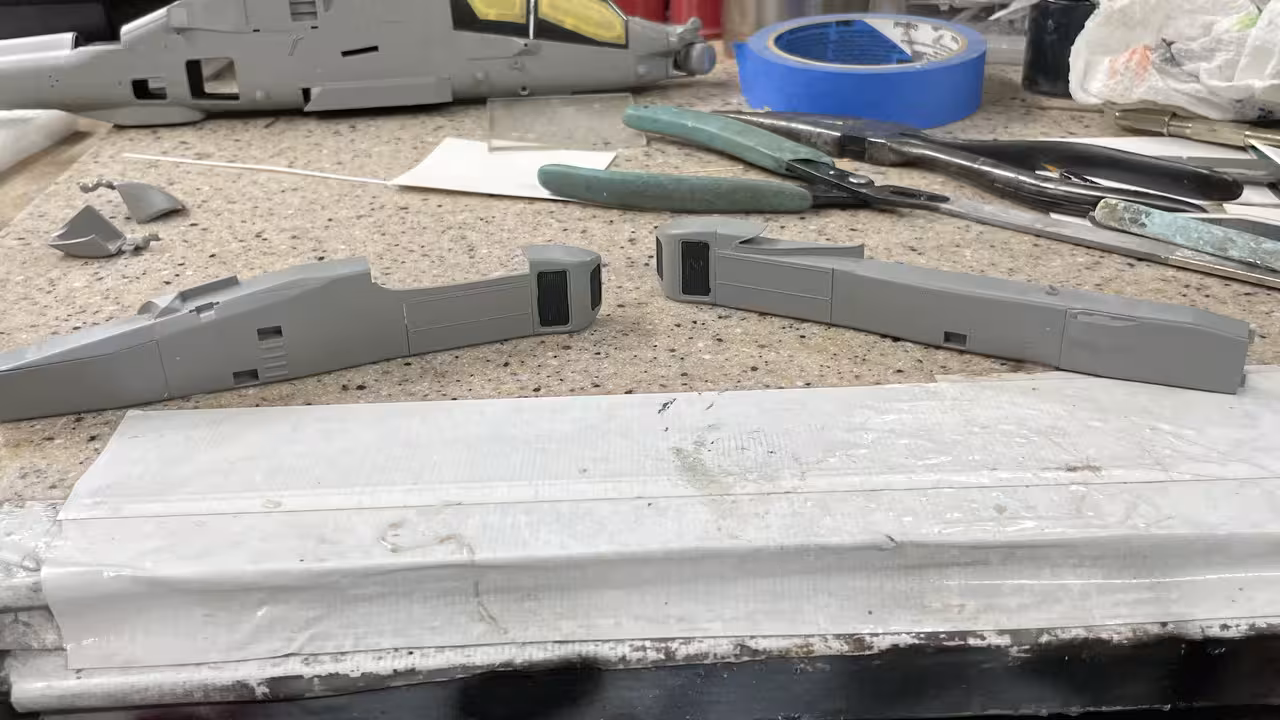
I started working on the two sponsons. I’m not opening the equipment bays. My friend is not a critical model observer and I don’t want to spend the many hours to detail these areas if they’re not appreciated. Furthermore, I have some big stuff in the queue and want this model done by the end of July when I deliver the turret model to the New Jersey.

It was quitting time (5:00) and when changing out of my shop shirt, I reached in the pocket and guess what I found? P53! I swear I checked that pocket early on in the search. Absolutely drove me nuts!

Brings up being able to rip out work when glued with canopy cement. I removed both glazing pieces and will install the correct part tomorrow.

I’m bringing this model to Philly with me when I deliver the turret model. I’m building it for a friend. If you choose to build it with blades folded you have to leave off the Long Bow radar. The folded config is only used when airlifting or shipping the Apache. And the Long Bow would create head room problems. It’s an entirely manual affair, unlike a Seahawk where blades are routinely and hydraulically folded for shipboard stowage. It would be easier to build with blades extended since the folded blade support system is finicky, complicated and looks a bit frail. I know that the Seahawk’s support frame was a fragile mess that kept breaking right up the show last September when i got a 2nd place award for Helicopters. That said, I don’t believe my friend has the display space for a 1:35 Apache with it’s full rotor width.

Today, I glued the errant part P53 in place.

I cleaned off the dried canopy cement from yesterday’s attempt and then reglued the glazing with the P53 properly seated below the glazing. It’s why the glazing had to come off. The glazing sits on a lip on the P53 which had to go in first. There’s a lot to do before O.D. goes in on those windows. I trimmed those styrene strips in prep for painting.

Got back to work on the sponsons. There’s two PE grills that go in on each side which are retained by a narrow plastic frame. Went in without too much fussing.

I read and made notes on all the review builds of this kit. One of the things that caught my eye was installing the stub fins now instead of much later in the assembly. If you wait, they will not go on! The fit is nested within the sponsons so you need to do them sort of simultaneously. I assembled the two wings and did some trial fits to the fuze. It’s a very tight fit. They also say that it’s wise to slightly thin the wing’s broad tab so it’s a nice sliding fit. Right out of the box it’s almost a press fit and all that pushing and shoving can lead to bad things.

Here’s the port side wing alone. That upper fairing is a separate part.

The upper fairing completely fills the opening on the sponson and would be very difficult to install if the sponson was fully glued in place.

And here’s the sponsor during a trial fit. The Takom kit has very nice Tamiya-like without needing little or no filler. This is the strb’d side. Can’t glue this in yet. You have to capture the main landing gear inside before buttoning up. That, of course, complicates things. I purposefully clipped off the pitot tube since it was bent sideways. I will replace all these tiny tubes with piano wire later in the build…

Got the sponsons installed. It’s a very challenging aspect of the build and lots of folks have written about it… including this author. It’s theoretically a snap fit, but to accomplish that you much manipulate many things at once. Before that I replaced one of the pitot tubes with an assembly of Albion Metals telescoping micro-tubing. It’s all held together with thin CA. I have this tubing in Aluminum and brass, and it’s very useful in making miniature pipe fittings for super-detailing jet engines.

The main gear is a challenge. The oleo strut should glue into the bracket on the main strut, but immediately I pinned it. It has to be flexed a bit getting it into place and having this joint movable is necessary (just like the 1:1). You also have to reduce the size of the half-moon pin. It has to engage in a similarly shaped hole in the fuse. It’s a blind fit and if you have to push it in (or worse… if it doesn’t go in) you will break something.

The gear is installed in two locations in the sponson. They are not particularly secure and even with gluing, tend to come apart when doing the final asssembly. There are some tiny parts that attach to the gear that you leave off at this time. They will not withstand the handling that follows. You can add them later if you’re so inclined.

The pushing and pulling I did during my attempt at installing the sponson, broke that lug. It, however, wasn’t critical and the gear is secure anyway.

You have to coordinate three things: getting the gear into their respective mating spaces in the fuze, getting the stub wing settled in, and pushing the sponson onto three large openings that correspond to the big pins in the sponson. The Stub Wing’s very tight fit into the sponson greatly limits fore and aft degrees of freedom. You have to get all the pins into all the holes, even though some are completely out of sight. And you must do this without applying undo pressure.

This whole deal took a lot of time. I was getting frustrated and was thinking of building it without landing gear, but the Apache doesn’t have retracting gear so that possibility was moot. I perserved! Eventually it snapped in place. I ran a stream of glue (Tamiya) around the entire perimter. The fit is amazing.

Peering into the innerds, you can see the sponson-side mounting lug. You cannot see the fuze side which makes this whole affair so confounding. It’s also why that pin must be reduced in cross-section so it drops into its hole. You can’t force it!

Now… with all that said, the second sponson dropped into position almost instantly and snapped solidly in place. Don’t ask me why this happened or what I was doing wrong with the first side. I have no idea! As Mark Knopfler says, “You can get lucky some time.”

So here were are as now. Notice I broke off the Long Bow mast… AGAIN! I had already glued it with metal reinforcement. It broke right at the end of the metal rod. This time I’m going to replace it all with metal if I can. I hate long plastic shafts like that. I always break them during assembly when I’m doing something else on the model and holding it wrong. I’m waiting to whack the tail rotor shaft. Don’t know when it’s going to happen, but I am sure it will. I should replace it with metall before it happens.

Lots of diffierent things going on today. Before I get into that, my wife had radical breast surgery in January after a cancer had returned after 16 years. She had chemo afterwards to reduce the possibility that any renegade cells got away. Then last week she had a followup bone and CAT scan just to make sure nothing was going on. The CAT scan found a 1cm “Enhanced Nodule” in her liver. Panic ensured. She had an MRI to confirm what it was (or wasn’t) at 8 p.m. on Saturday night. Today we got the good news. The 8mm nodule is benign, basically harmless and will never turn malignant. We needed that good news!

First thing I did today was make a brass sleeve that will positively connect the broken mast section to the existing stub. I will modify the part that joins here so it accepts the sleeve.

I then started working down the port side putting in the various and copious details contained in this model. The first was a grilled access cover. The instructions call out some internal pieces… you will never see them so I didn’t include them. The grills are on PE Fret A. There were three of them.

I installed them onto the part before gluing the door to the fuze. I used Tamiya Gel CA. Gel CA gives you a lot of working time, doesn’t wick where you don’t want it and cures quickly with a tiny bit of accelerator when you’re ready for it to set. The round one got a little banged up in this operation.

Next up were mounting blocks for some countermeasure sensors. Takom couldn’t just injection mold the part with the bolt patten behind it. Nooooo… they had to have a PE flange that sandwiches between the two-part styrene and the fuze. This precluded using Tamiya thin cement to do the gluing, which was now done with gel CA.

And then there was another styrene/PE composite part with this odd, rear-facing vent… Anyone know what it is? Tail rotor Oill Cooler??? And again, had to put it togther with gel CA. I used the Small Shop Little Bender for this small PE job.

That finished the port side for these things. The starboard side has similar components. In this case, just for fun, I added the internal, unseen details on the access door.

Lots of stuff and a waste of time unless you like gluing stuff for fun.

This side had it’s own passel of PE grills.

This step also called out of a very frail, 2-part, styrene antenna structure. I didn’t give it a second thought. I was going to replace this part with metal. It wouldn’t last five minutes with the way I build models. It measured 0.031" in thickness, which is very closse to 0.032" wire I have. I have an American Beauty Resistance Soldering Unit that makes putting together precision soldered assemblies enjoyable.

Holding the stock against the master I marked where the bends would go and use a jeweler looping pliers to give smooth and accurately placed bends.

For the support brackets (also measuring the same size), I first flatten an end to form the attachment loop. I use a very old, very strong, very reliable Vise Grip, that must be from the 1960s (my dad’s) and with the jaws at fully-closed locked position, keep squeezing the stock and turning it over and using the side entry and front entry to the jaws to get it as flat as possible.

Here’s how the flat looks.

After forming the loop, trimming any excess preventing full closure, I trapped the rod in the joint, and then, using a MicroMark ceramic soldering pad, setup the job to be soldered. With the RSU, the joint is made in seconds. I use very fine gauge rosin core solder (.5mm).

I’m pleased with the final result, and although it might miss some small details, it will survive handling and the 700 mile trip.

I have some 3D printed fitting that I’m going to use for the right end. There’s a plastic kit part that was supposed to glue there, but I’m going to change that.

So it was a pretty good work day…

I had 3D printed some 1:24 pipe fittings for last years NASCAR car build and I was able to put one to use as the fuze terminator for the new metal antenna.

I then installed two ridiculous PE ribs that adorn the top of the fuze. I hate gluing this on a 0.005" edge. I used a combo of J-B Structural Cement and CA in that order. The J-B will hold a bit longer and more secure to the metal/styrene bond, and the CA helped hold it all in place until the J-B sets (which is sloooooowwww). The first one was a bit of a fuss.

The second one was much easier…. learning curve. If I had to do a third it would even be better.

I put the fuze asside so all this would cure solid and got to work on the GE engines. This kit suffers from part over-indulgence. There are parts with glue surfaces that are much less than 1mm sq. They are so fragile and untrusty worthy that I’m considering closing both engine bays and not worrying about it. For the Seahawk I used the ResKit engine and now I know why. Doing all the doodads in styrene is folly.

The first horror was this pipe array that HANGs on the side. One end glued into the engine proper, the valve body glues to a tiny appendage hanging from a pipe array that glues into two spots on the engine.

That hanging joint came apart three times.

Making matters worse is another pipe that’s supposed to tie into the top of the valve body and glue to another pipe that’s just hanging out there. Then came the accessory drive. Instead of molding all the various bits to the one side of the two-piece body, they made them all separate pieces. I lost one. And there’s an oil-filter looking thing that’s even attached in a more precarious way (if that’s even possible). This piece fell off three times. I used Tamiya Cement. Then Bondic and then CA. None of it worked. Bondic, doesn’t always adhere too well to styrene, and didn’t in this case.

I’ve thought about replacing all the piping with metal and/or reinforcing these tiny joints with wire. Trouble is that the joint are so tiny that even drilling with a 0.010" drill weakens them further causing more breakage. The kit is over-engineered to drive up parts count. While it impresses, it doesn’t make for a satisfying build.

I persisted with the engines and have had marginal success and will have at least one bay open. I also changed the assembly routine to more closely follow the instructions. It was easier to glue all the apparatus to the accessory drive when it was off the model than attached. This is also true for the grit separator. I tried to glue the separator drum onto the dirve without the manifold. With the second engine I glued the manifold to the separator and then will install this as an assembly. This provides two points of glue contact at each end and supports it while drying.

The compressor section has simulated bolt circles that are glued in in half-circle segments. One broke in cutting from sprue.

It complicated the gluing task, but I got it on. I also figured out the cutting sequence so it didn’t happen again.

Cut the center lug first, then cut the ends. The removes the stress point and lets the ends flex under the flush cutter.

I lost another tiny piece for the accessory drive for engine #2. No one will notice, but it bugs me, that even with my parts catching drape attached to the work bench and clothes-pinned to my shirt, the darn things still get lost. Also, here’s that part that has almost 0 glue surface. I don’t know what Takom is thinking. It’s not even possible to wire this piece on. Just not enough part to drill. I’m leaving it off. Also the little pipe extension on the part is already breaking off and I have done anything to it yet.

Speaking of breaking off… One of the styrene pipes already had an end broken in the sprue leading me to use .5mm solder without giving it a second thought.

Here’s the first engine mostly complete. I have to decide when to pipe it some more.

Here’s the second engine ready for final assembly.

There’s a lot of piping that can be added. These images also show the major color variations on the various sections of the powerplant.

I did add all this to the Seahawk engine and almost went blind in the process.

On another front… my next major naval project is an attempt to make a 1:48 model of the Battleship New Jersey’s #3 Engine Room. Ryan Syzmanski is excited by the thougt of having this on the ship, as am I. The main problem was the lack of detailed drawings for all the machinery and the room’s layout.

I did some research and found it. There are original drawings of exactly what I’m looking for at the National Archives. The only problem is they are not digitized. I will have to view them in person. They are at the National Archive repository in College Park, MD. I need a National Archive Researcher Card, which I’ve applied for.

I will be able to copy and photograph the drawings. There are 160 of them in the set in which I’m interested, so it will take some time to find what I need. I’m excited by this as it seems the chase will be as much fun as the capture. I know I can draw and produce what i need to create the model. The challenge was finding information about it. That seems to have an answer. I will be posting this all in a separate thread when the time comes.

Work continued this afternoon.

Finished up engine #2 and prepared the heat shield PE brackets. There were fine slots to accept these little parts which aided in getting them situated. I initially used the J-B cement again, and stabilized the joint with some thin CA. It will dry by Monday when I’m back in the shop again. That said, the zero (or near zero) area at the other end that supposed to hold these panels over the engine is worrysome. I don’t like these kinds of joints. They make for very fragile assemblies and this model’s going to have to take a trip. I may add some styrene bits on the engine to give more gluing surface to make it more secure.

Here’s how that part goes onto the model. I think you’ll agree that it’s dubious at best. Just because you can make something close to scale thickness with PE, doesn’t mean you should. You won’t see these brackets and they could be styrene and much thicker. The diagram doesn’t really show exactly how this part is supposed to fit. It does look like the case bolts engage in the four holes in the rear bracket.

While this was drying got started on the exterior exhaust system. Unlike the Seahawk which has a straight out tailpipe, the Apache has an elaborate “exhaust cooling” arrangement that mixes cold ambient air with the hot exhaust stream to mitigate the threat of heat-seeking missiles. The exhaust splits into three chambers, each with top and bottom inlet screens to bring in the outside air where it blends with the hot exhaust stream.

There are six units and they are different. The instructions label the manifolds rom A to F, and the mixing boxes from G to J. I made a chart to keep them in order.

There’s a PE part simulating the inlet grills that I glued on with gel CA and then applied accelerator on the top of the screen to cure the stuff quickly.

I assembled the first set to the engine outlet. I sat and thought a while about the painting sequence, i.e., paint before exhaust or after. I settled on painting after. The decision was based on getting a very solid glue joint on this fragile assembly and that would be without paint.

Quitting time was approching (it was cocktails Friday night), but I wanted both sets assembled so they would be perfectly cured for next session.

The next steps include putting on the skin around the engine. Painting and further engine detailing (if I decide to do more) needs to be done before then. From photos, it looks like the manifolds are natural metal, probably stainless or titanium. The grills are black as is the exhaust outlet from the mixing boxes. It’s amazing that this power pack, weighing a bit over 500 pounds puts out over 2,000 hp. Gas Turbines are very efficient.

Sporadic work sesssions before the 4th. I did get to test fit the engines into their housings and continued building up the engine shrouds. I have to paint things before going further.

The instructions don’t tell you if it’s better to glue these two parts together before or after attaching them to the shroud base. Because of the critical nature of the fit, being a long edge with no tabs/pins, I chose to glue them now. Glad I did as it’s much easier to fit them on the shroud base when they’re together. The joint is basically invisible.

I also glued the opening portion of the shroud that serves as a work platform. It was a challenging joint with very little surface area. I let them dry for days and they’re nice and secure. The prototype photos shows aluminum-faced batting in the square spaces n the door that is probably heat insulation. I’m going to simulate that with Bare Metal Foil (after painting zinc-chromate green on all the rest of the insides.) There’s another frail “telescoping” support pole that connects these two parts. I may make it out of metal since it looks very prone to breakage.

I test fit the shrouds (before gluing the doors) to the fuze. They needed a little relieving on their rectangular pins to they weren’t a press fit. Press fits are bad when you’re gluing delicate assemblies.

The engines engage the slots at the bottom. Before they go in, besides paint, there are a couple of unseen details that go in under the engines. Shrounds are not glued in.

There are also two, frail plastic bars that tie the exhaust coolers together, one on top and one on the bottom. The gluing surface to the tiny bit of styrene that’s sticking up was way too small for a good joint. Before gluing I had to pull the three manifolds together and CA them so they were touching. Otherwise, the bars would not align to their pins. I then used Tamiya cement and followed up with med CA. The long one, engages in a hole in the fuze. The short one looks like its end glues to the upper shroud assembly.

You can see where this bar engages the fuze. Nothing glued… all test fit.

With both engines fit it looks very busy.

I have another “commission” project for my wife’s cousin. Found out recently that he was a flight chief on a P2V-5 Lockheed Neptune during the Cold War. I found a Hasegawa kit on eBay and will build it to his plane’s id.

Decals were very, very old and yellow so all need to be redrawn and reprinted. Not being able to print white, and using white-background decal paper, means that white lettering either has to be individually hand cut and placed, or I have to match the glossy sea blue background and have the lettering connected with the background color. I’ve done this before with decent success. it just takes a lot of fiddling with colors on CorelDraw to get a match with inkjet ink. I make color swatch sheets to do it. Last time it took 14 test colors to get it close. If I use Vallejo Gloss Sea Blue, I already have a match for that color. I don’t like Vallejo since it takes so long to dry. I’m thinking about using Mission Models colors. Not sure I’m going to post this model.

Here are two pictures of his actual plane. His plane was the one that tested the nuclear depth charge in the early 60s. Historic!

It DID NOT have the top gun turret.

The Neptune was one of the first Piston/jet craft made along with the B-36. The piston engines were the amazing Wright R-3350-30W. These were the final evolution of radial engines with turbo-compounding. Instead of using exhaust to drive a supercharger (turbocharging, the three turbines were geared directly to the crankshaft through a fluid coupling. They created an additional 500 horsepower. There’s a cutaway version of this engine at the Franklin Institute in Philadelphia that really impressed me as a kid. I had no idea how special that arrangement was. The three exhaust stacks spaced around the nacelle equally (180º) is one of the ways to identify this engine. The engine produced 3,700 hp with the same fuel consumption as the ubiquitous R2800.

This engine was also found in the Lockheed Constellation, the DC 7, and the Globemaster 1 cargo plane. The B-29s had the 3350s (along with the A1 Skyraider) but they weren’t the turbo-compound model. 3350s were also one of the first engines to have direct injection into the combustion chambers to rectify the fuel imbalance problems. There’s a nice docuementary on this engine. It was a monster to perfect an there were 8,000 engineering changes before it finally proved itself. And it did! They make over 8,000 of them.

Being a flight engineer on these piston/jet planes must have been wild. They used the jets for take off, and had shutters that closed them off during cruise so they wouldn’t windmill.

Okay… enough digression. Every one who celebrates have a safe and happy 4th of July Holiday.

After the P2V fell when I was preparing to make a tail prop, it destroyed the main gear. I now had to figure a way to close the gear doors. There actually was no provision for this eventuality. And then I had to desgin, draw and 3D print a stand. I prepared the model with a brass shaft that penetrated the fuselage up to the top. I expoxied this into position with a J-B Epoxy formulated for plastic. I drilled the brass to accept a piece of 5/32" drill rod. I made brass sleeves that I inserted into the stand supports to accept this pin. I delivered the model to Larry two weeks ago during a trip to philly. It was also in this trip that I deleivered the 5" secondary battery model to the New Jersey. Larry loved the model since it replicated his specific plane and squadron.

I made a simple two-part stand and am providing him with 2 choices showing the plane in different attitudes. I painted the stand today and will ship it out tomorrow.

For a simple model, and a short build time, it was certainly challenging right to the bitter end.

Here’s a rendering of the stand directly out of SketchUp.

And here’s the painted stand ready to ship.

And that folks is the end of that.

With the P2V Neptune and the 5" Secondary Battery delivered, it’s back to the Apache. I painted the engines today. I also have a new Elegoo Saturn 4 Ultra. This printer is light years beyond my first generation Elegoo Mars, just five years ago. It even has an AI camera that records the print. I no longer have to run down to the workshop to check on progress. It can even do a times lapse photo series. It’s 60% larger than my Mars 3 and 40% faster. It’s 6 times faster than my Mars Classic.

I chose not to fully pipe the engines, but did enough to make it a little more complex.

I will be increasing my work on this model over the next few weeks. In October, I’ll be going to the National Archives to review the Battelship New Jersey engineering drawings to gather detailed information about the engine room project.

Wow! FSM Forum has come out of the shadows and now is running on a “real” forum engine where image import is direct! I had stopped contributing due to the inconvenience and then it stopped working altogether. Clearly, they were transitioning to this platform. That was a good decision. Lots of stuff is going on in my shop and I like to write about it. Needless to say, it was a battle finishing up the Apache. Takom didn’t make it easy. Parts are too small for styrene and I ended up replacing almost every styrene anntenna and foot rung with phos-bronze wire. Should had done it that way from the start.

Since this model was a gift for a friend and I had to get it too Bucks County, PA from Louisville, KY in one piece, I built it with the main rotors detached with the goal to assemble on site. I even went so far as to make U-shaped attachment pins to join the rotors during final assembly.

The transport went perfectly with a special cardboard-engineered carrier, but taking the pins out and inserting the blades turned out to be much more difficult than planned. The Arm to Hub joint on one blade failed during handling, and the thin mounting extensions on the arms were fracturing when i was trying to re-insert the pins. I ended up having to glue the blades on. Just getting plastic cement in Philly was, in itself, a challenge. There are no more hobby shops in Philly. Joe’s Train Store in Warminster, PA, has started filling the gap and has a line of Tamiya paints and plastic cements.

All’s well that ends well and the model is on display and its new owner is very happy about it.

And on the shelf with the saggy blades.

2 Likes