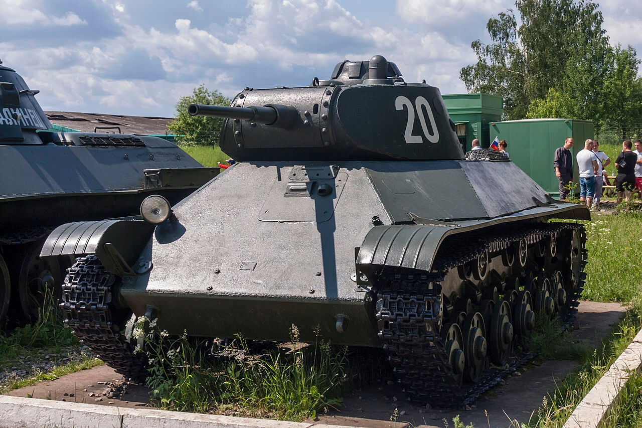
This is the T-50 light tank. There is lots on the web about it so I will not waffle too much about it. Here is the one at Kubinka.
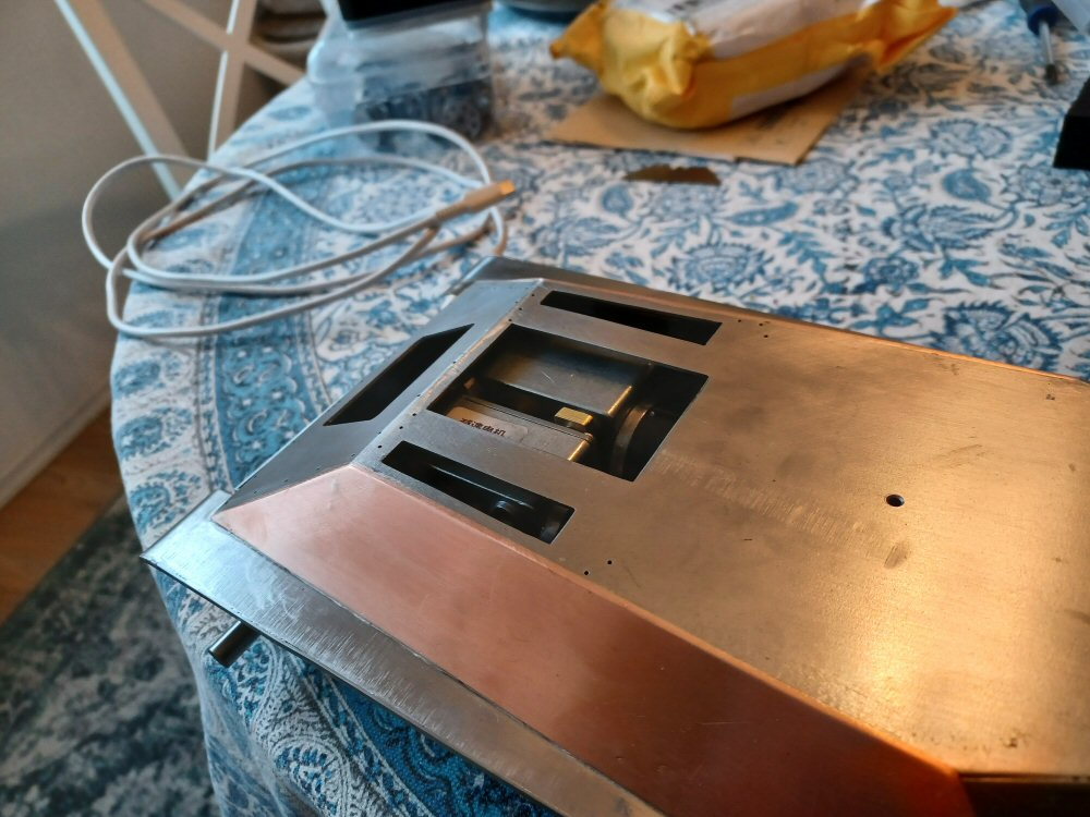
I will try and build this in 1:16 scale from scratch, the building materials will be steel primarily.
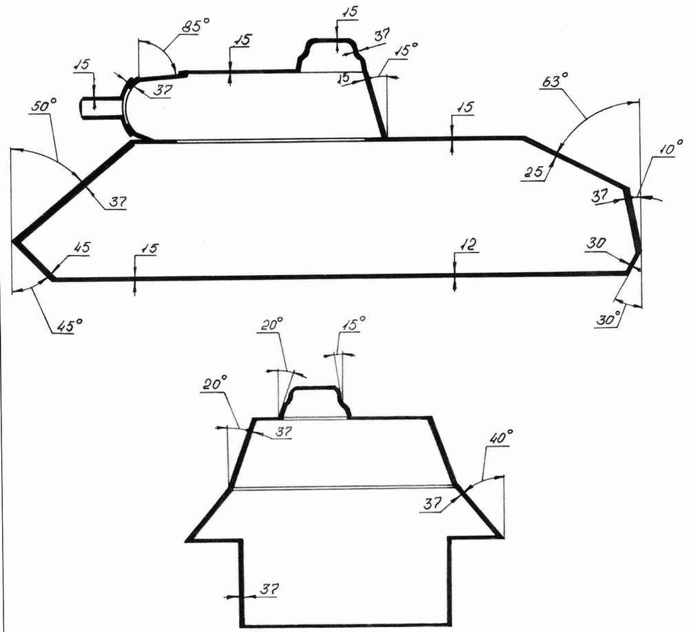
I built a Maresal some time ago and the angles drove me daft so I want to try and do another angled tank but try some new methods of getting the angles correct.
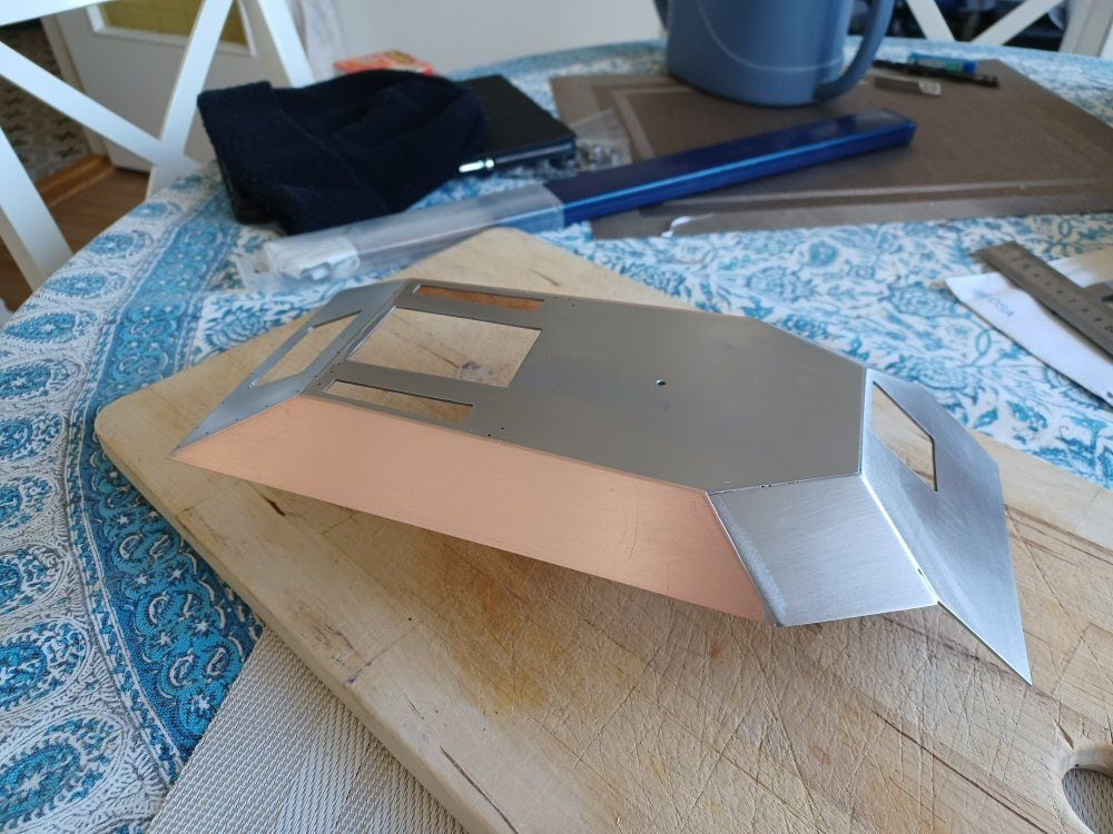
The relevant angles are in this picture:
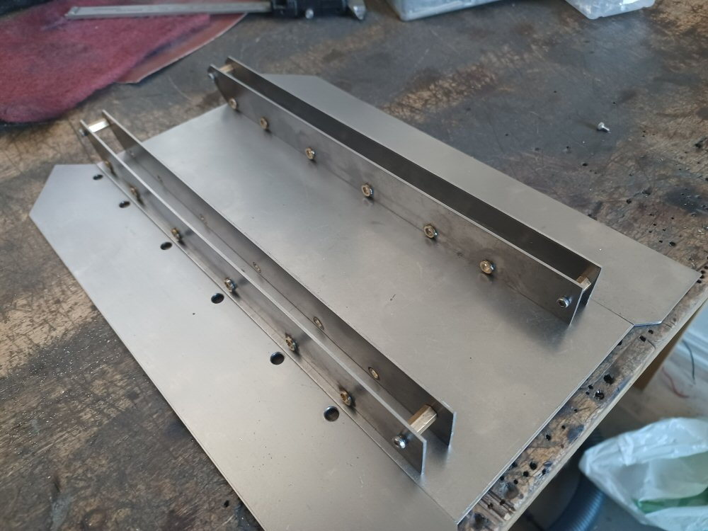
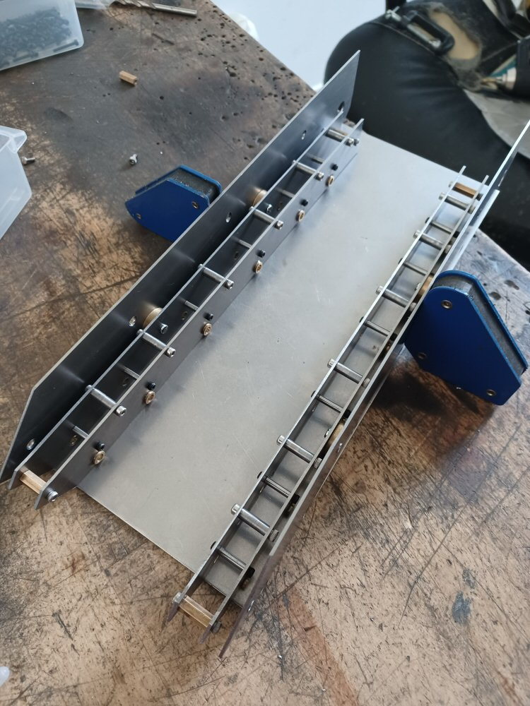
I bough these cheap from China to facilitate the angle placements - they are thick enough to work as supports and I have two sets which makes things easier.
I will use them like this to hold the plates for soldering:
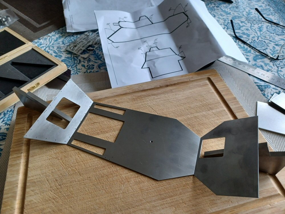
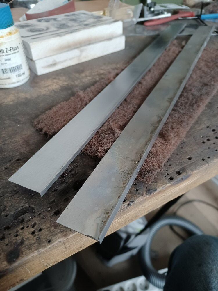
All structural bits are made from 1.2mm mild steel plate that I cut with a hacksaw and filed to shape.
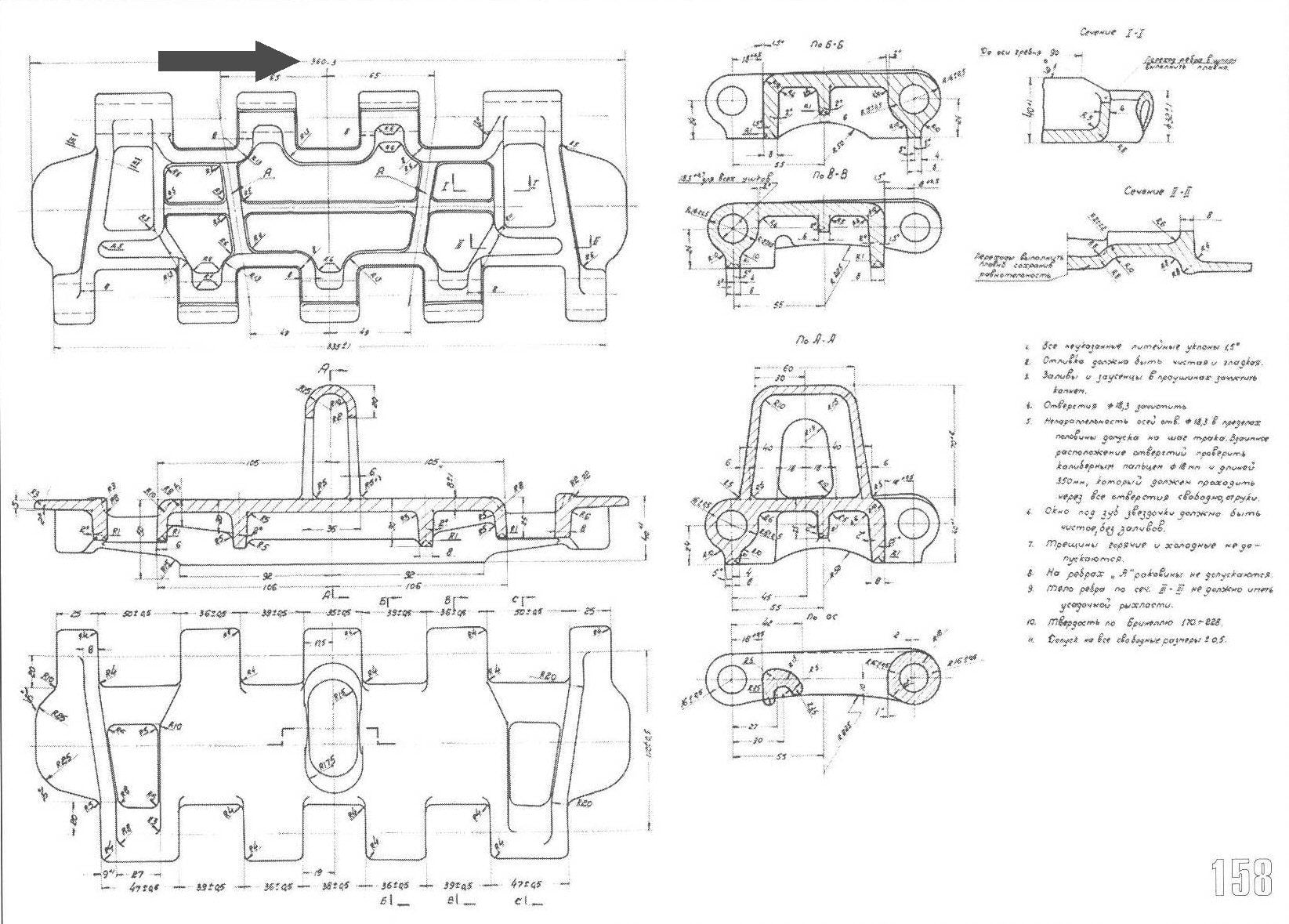
For tracks I am using Stug tracks as according to this:
the widths are about the same and it has the central tooth format which the T-50 had.
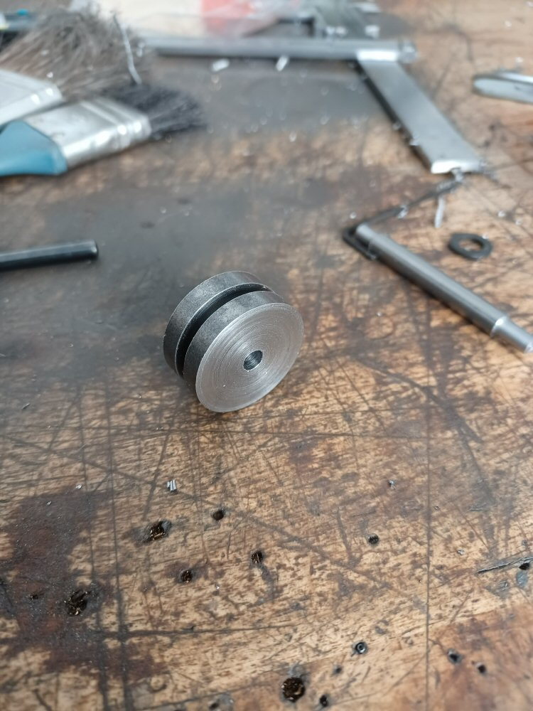
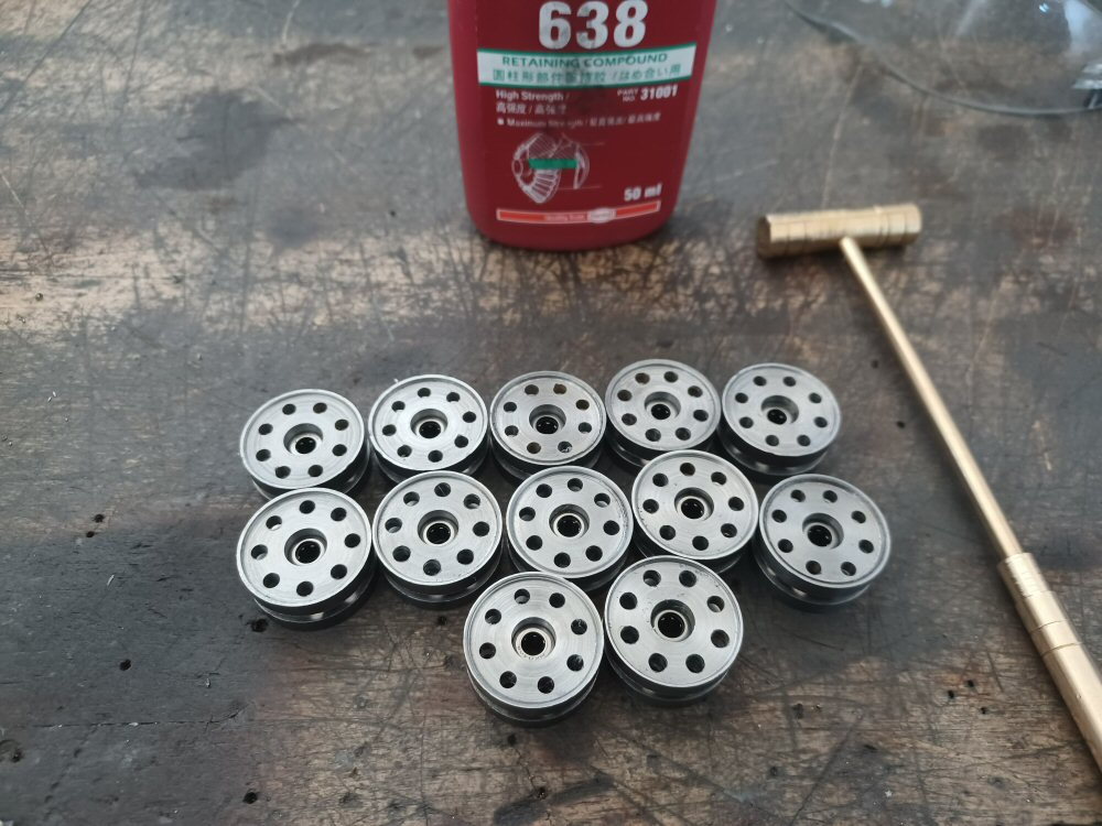
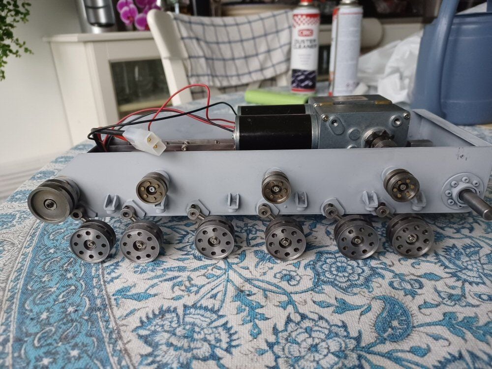
I started with the road wheels. Here are the blanks from stock steel bar.
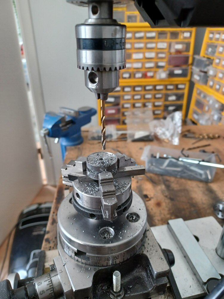
Then I abused my tiny proxxon drill for an hour to get all the holes made.
and ultimately ended up with these:
A major problem is this turret:
which is not symmetrical about any axis but I will get back to that later.
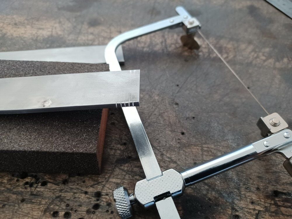
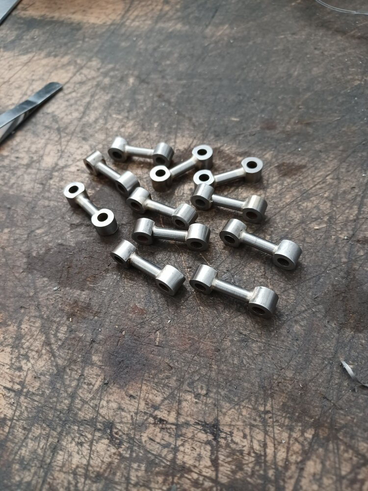
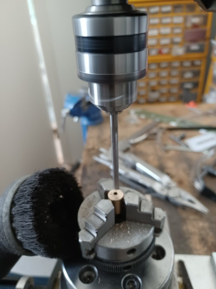
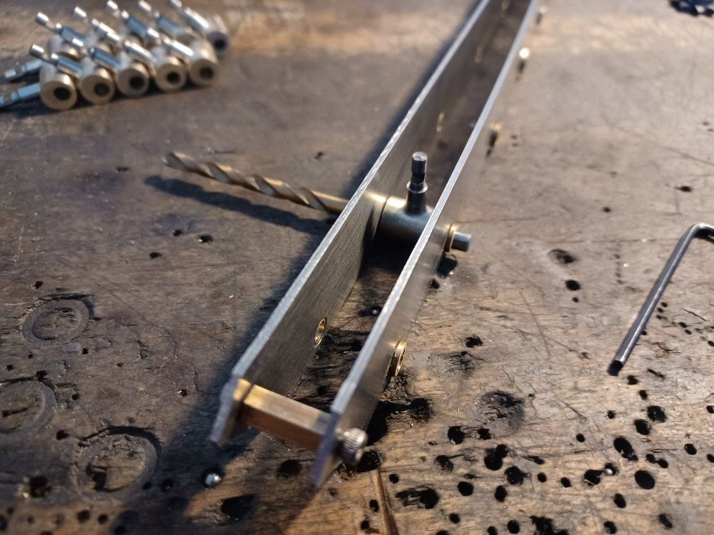
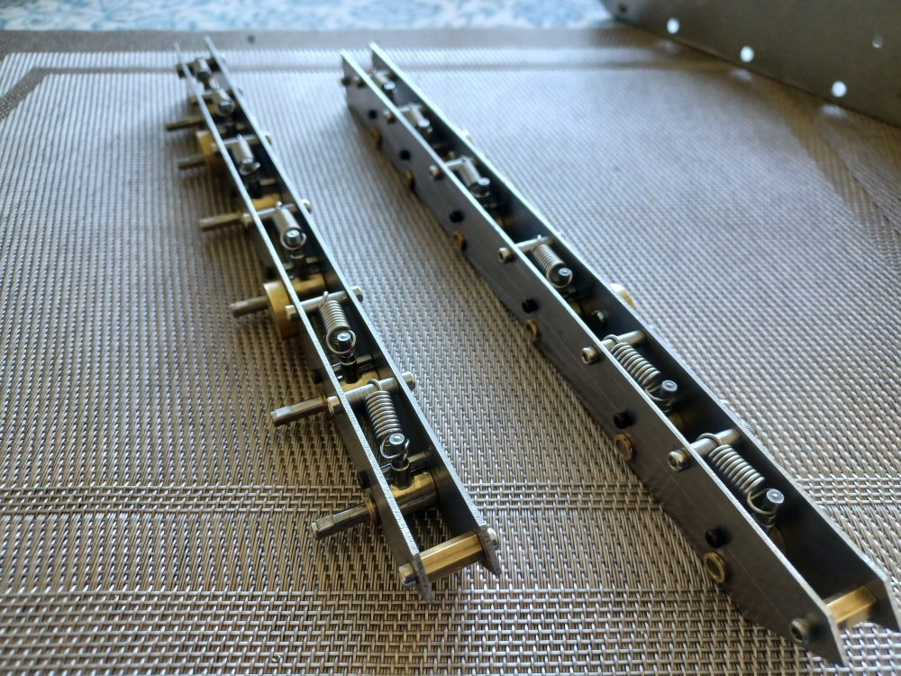
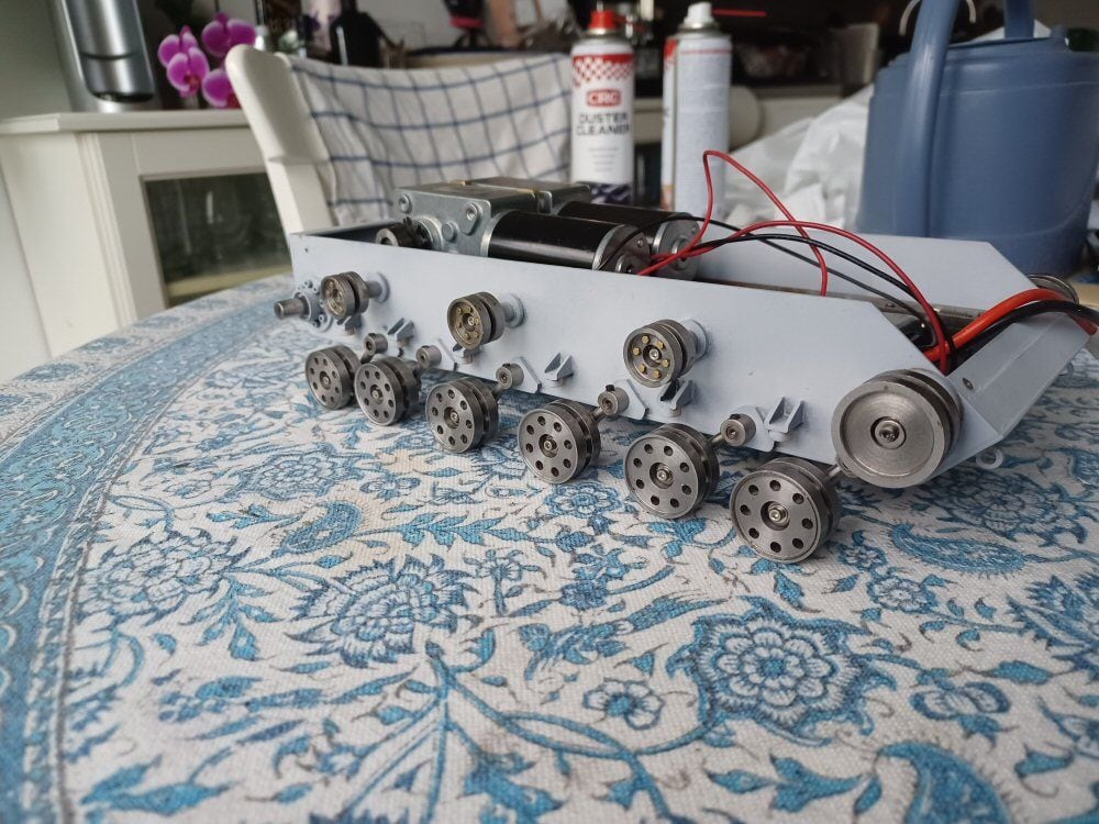
The swing arms are simple…some slices of a centre drilled 8mm steel rod with flats filed on them and then silver soldered to some 4mm silver steel rod.
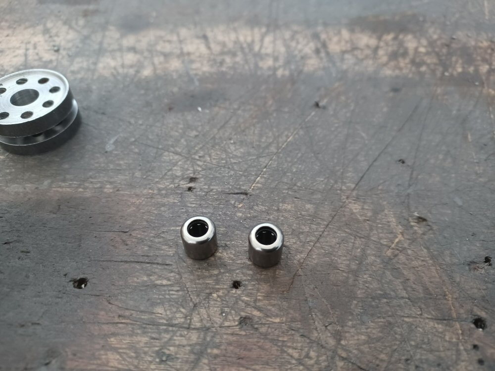
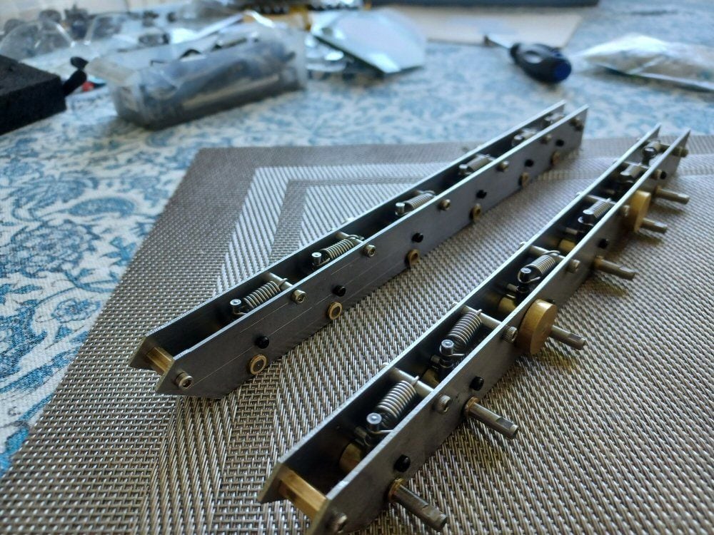
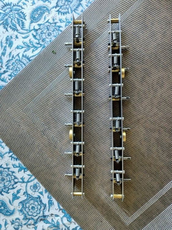
The wheels need bearings…I am using needle bearings as they are more forgiving if you cannot drill extremely precise holes. I used a 7.9 mm drill bit, drilled out the wheels and pressed in the bearings.
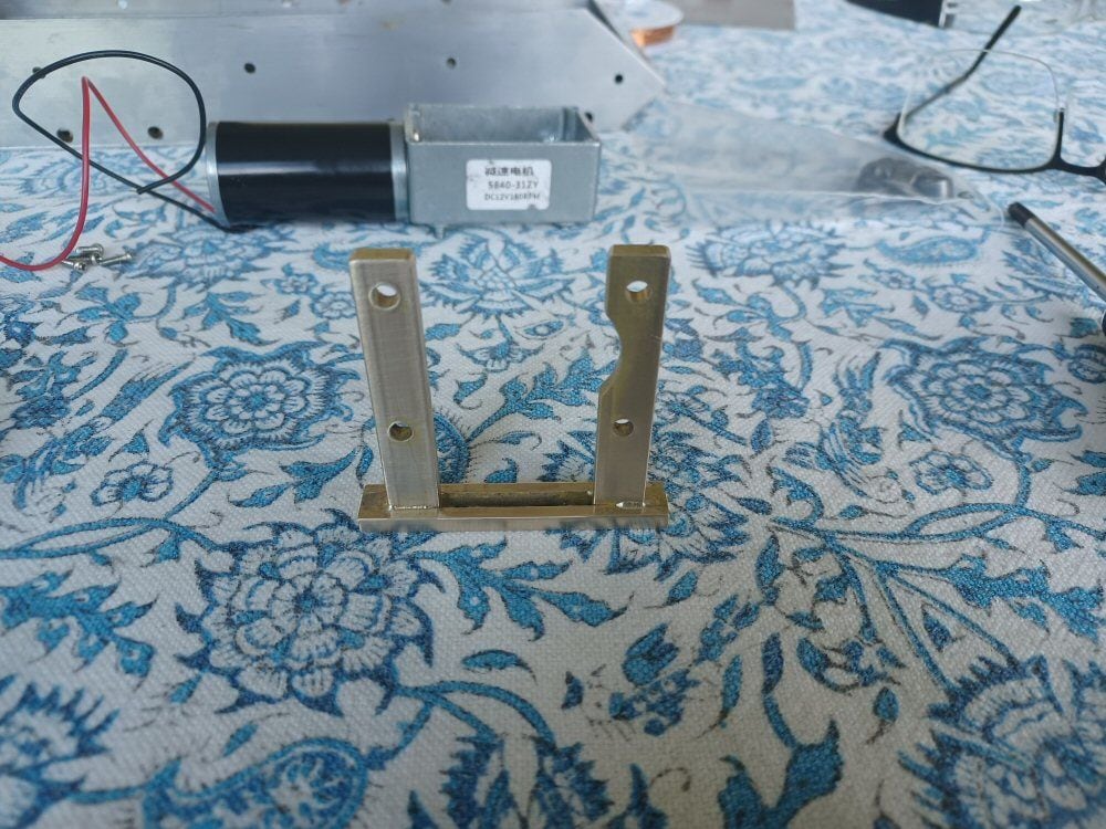
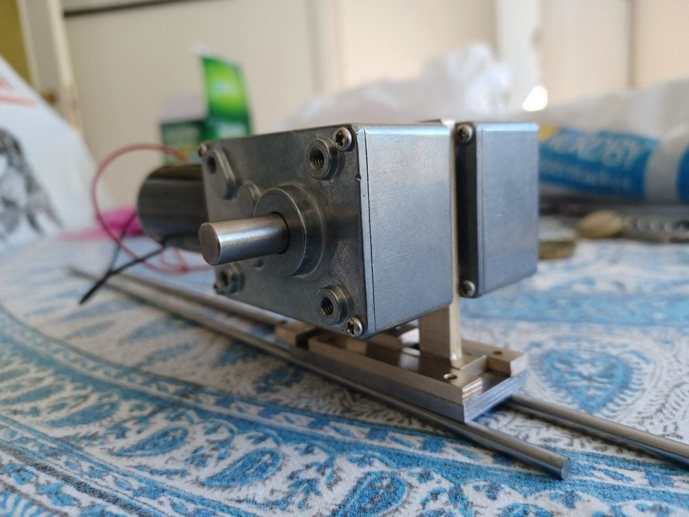
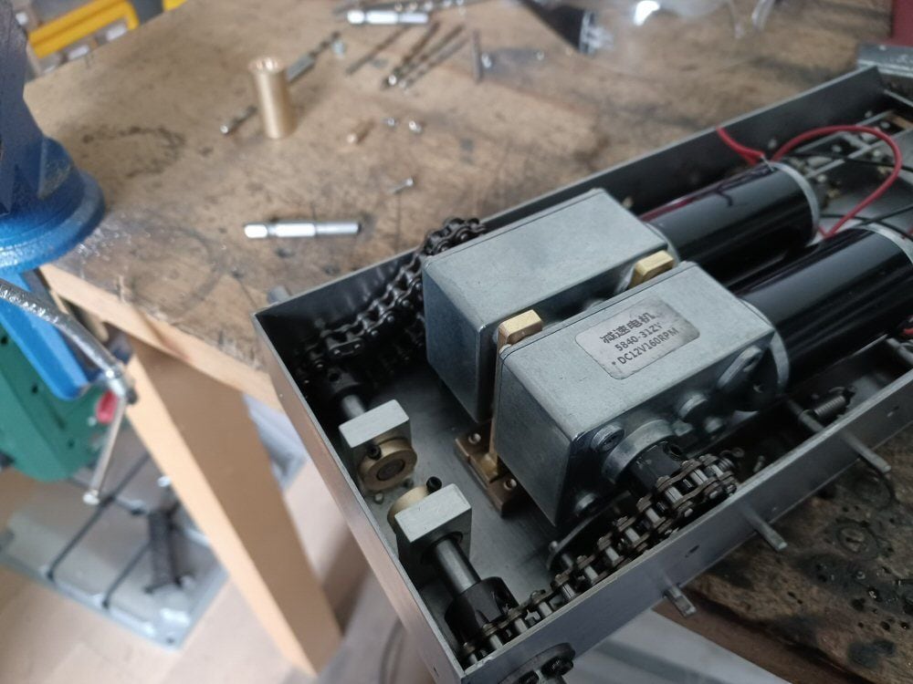
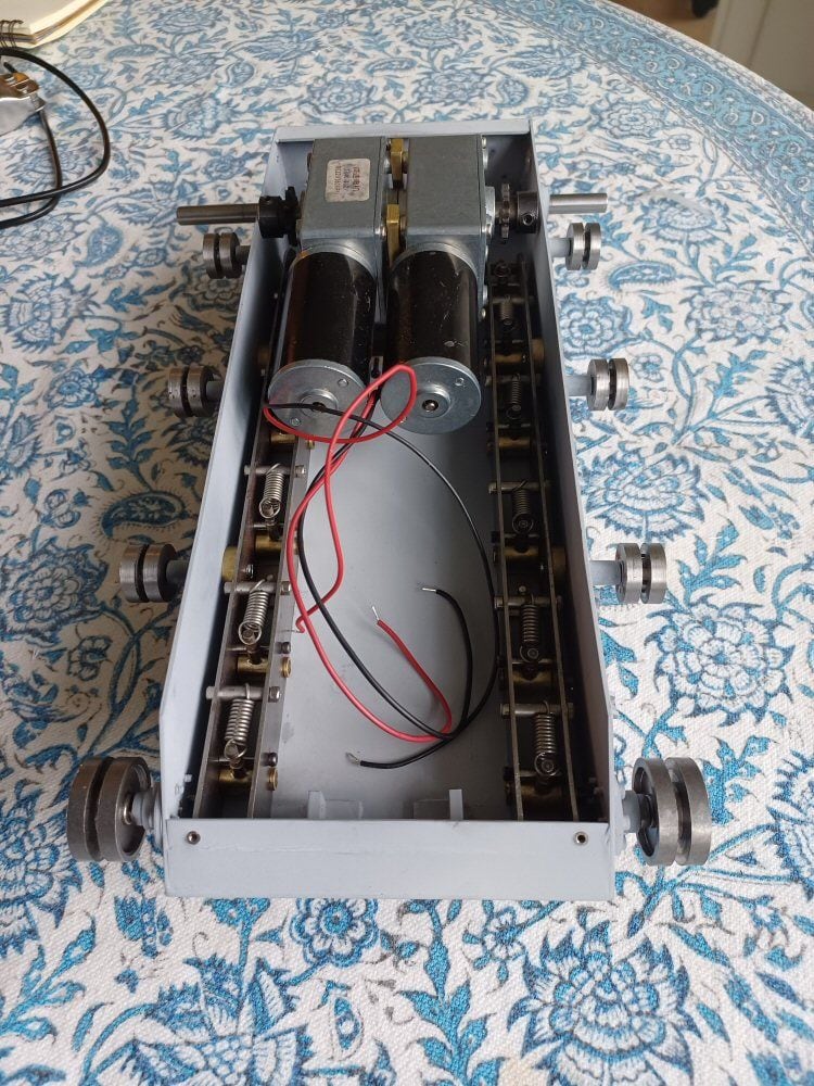
I like to retain the option of a moving tank so onto the motors. I am using big chuncky 200 rpm right angle motors from Ebay. One on each side.
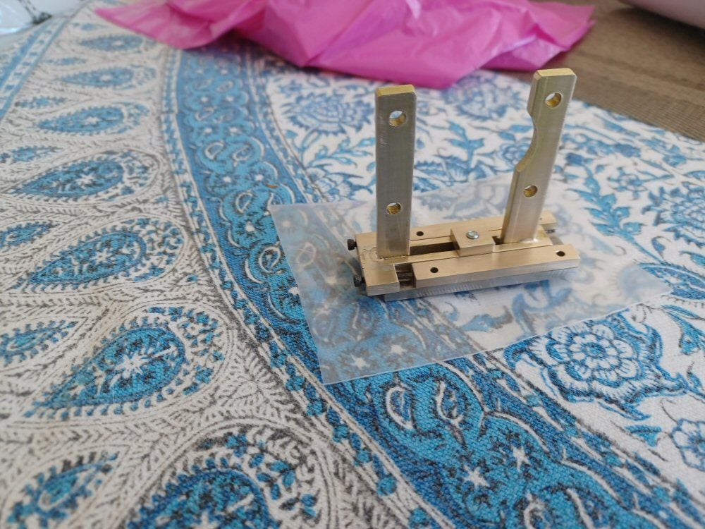
I need a bracket to hold two of them back to back so I fashioned on from brass bar stock.
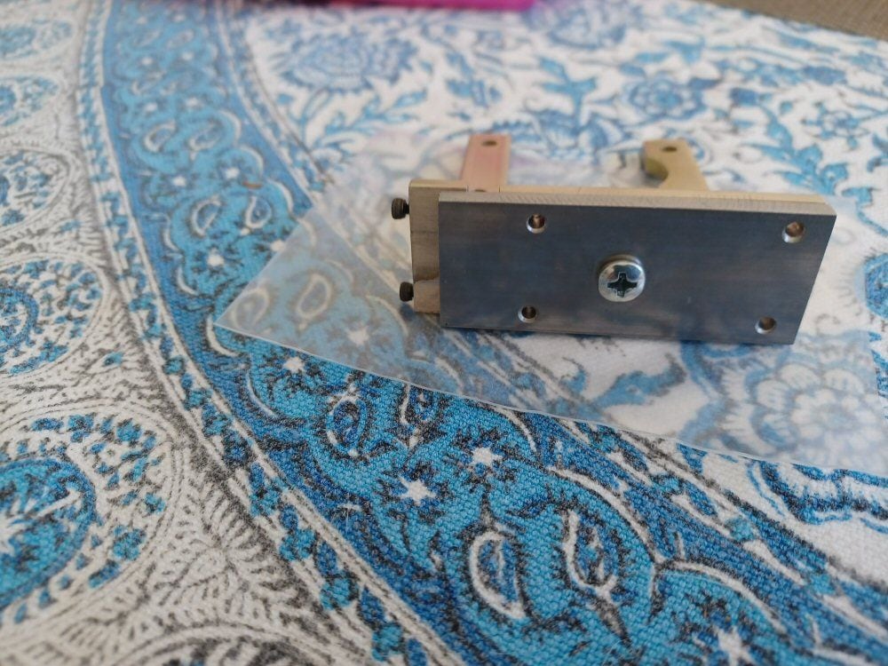
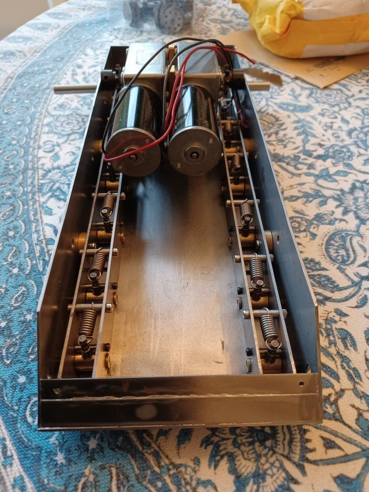
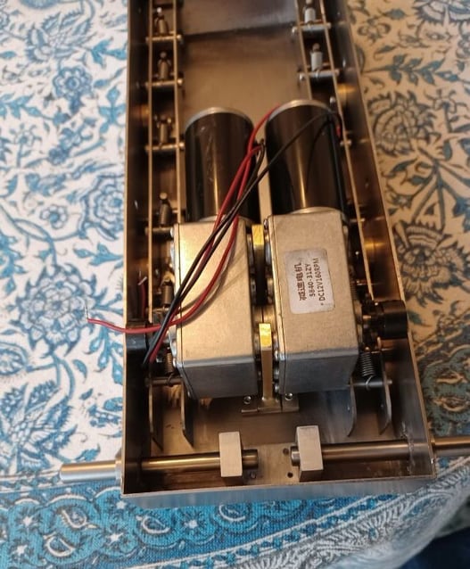
The motors will be connected by chains to the drives shafts so I needed a means of tensioning and slacking the chains. I mounted the bracket by a t-nut, accessible from the hull underside, and used two long M2 bolts as a means of adjusting the position of the motor bracket on the slide of teh base plate. Which can then be fixed using teh t-nut.
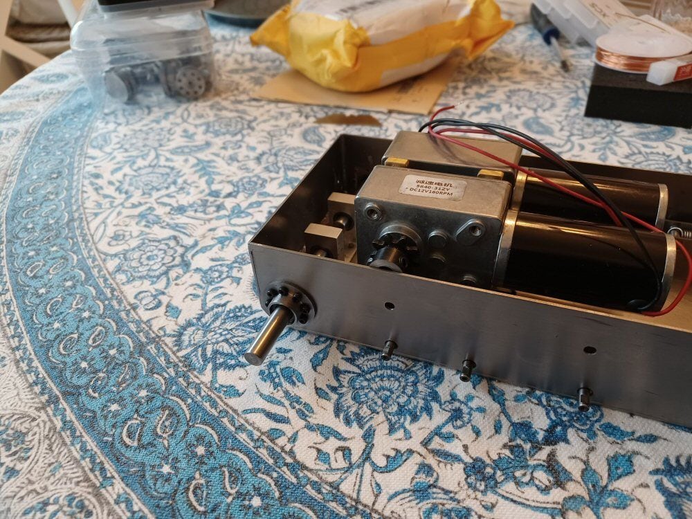
Here it is in position:
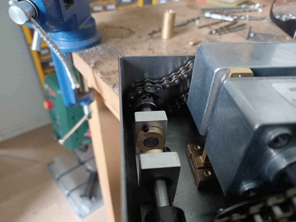
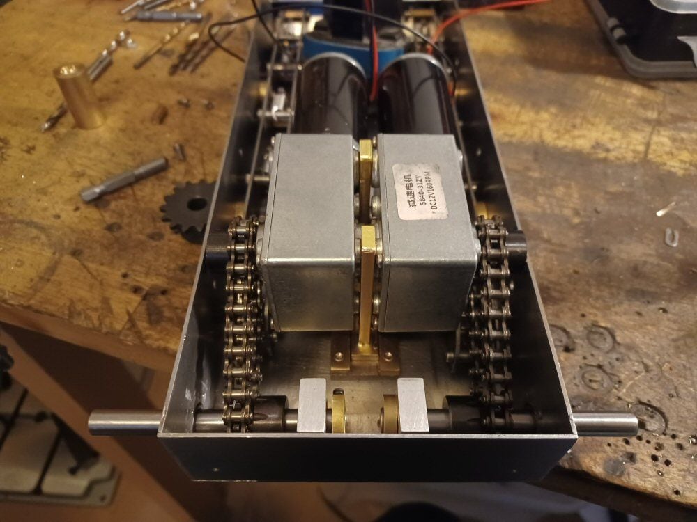
The drive shafts are held in place by a central moount with needle bearings and two hubs (one on each side) both holding needle bearings. The shaft is 8mm silver steel rod.
Here with the chains in place but slack:
And now tight. I had to move the sprocket position to the interior as the chains were fouling on the side walls of the hull.
And here is a little video of the runout on the axles after all that faffing about.
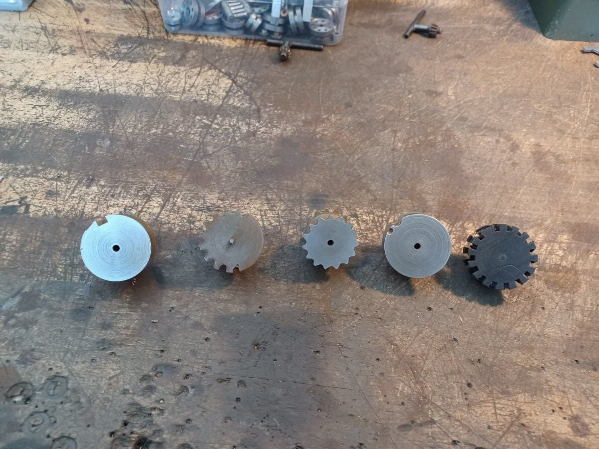
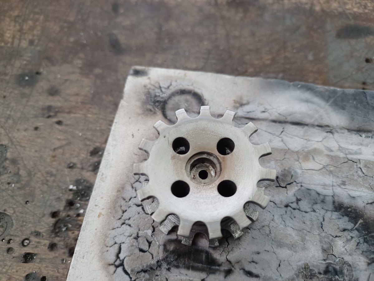
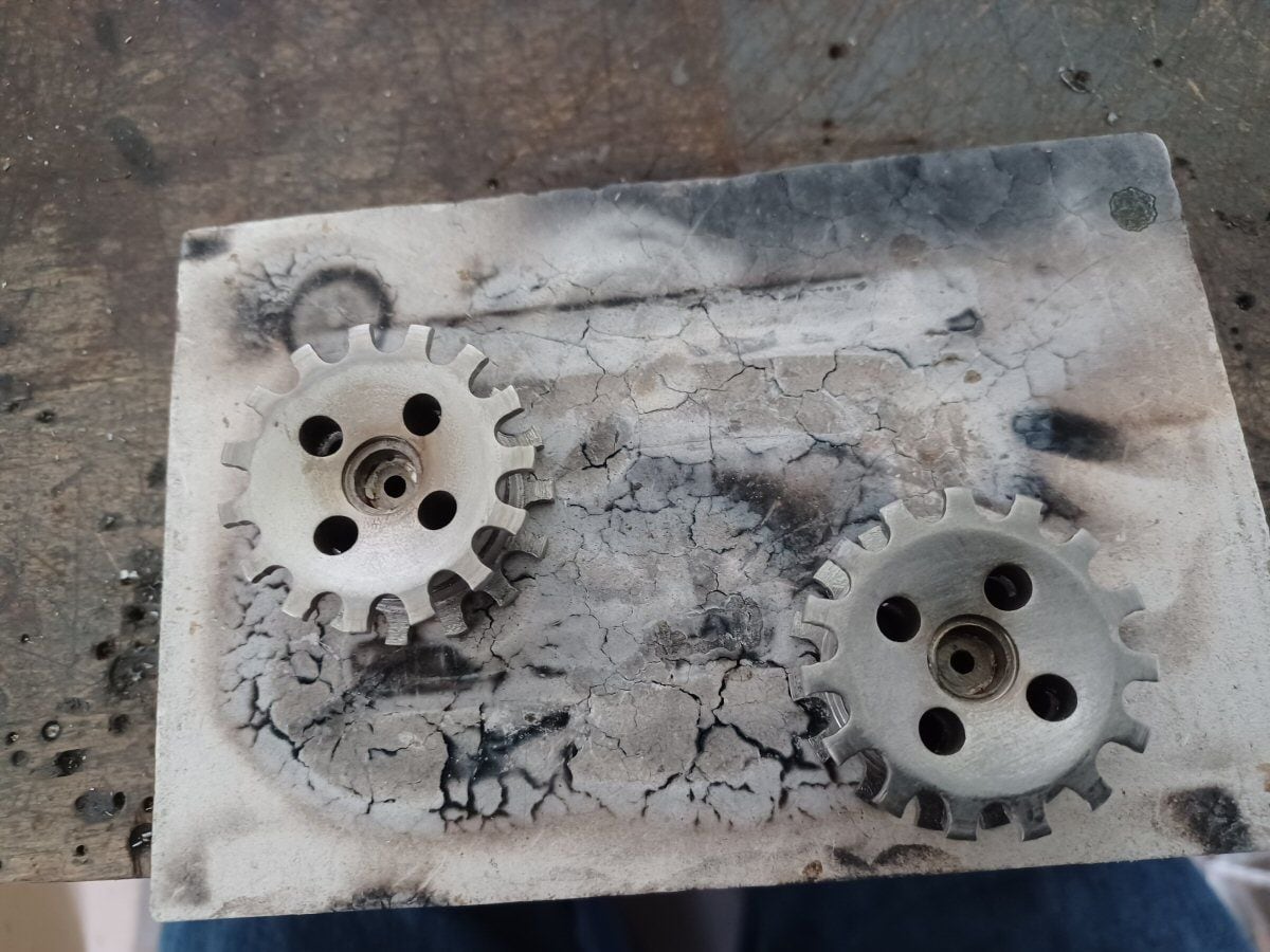
Now I needed a sprocket for the tracks. There is no one suitable available so I have to make one.
I calculated the chain pitch from the distance between the pins on the track. And used some formulae I got from the net to work out how many teeth I needed for a sprocket of teh right diameter.
And then wasted a lot of material trying to file in teeth by various means.
It was not going well at all.
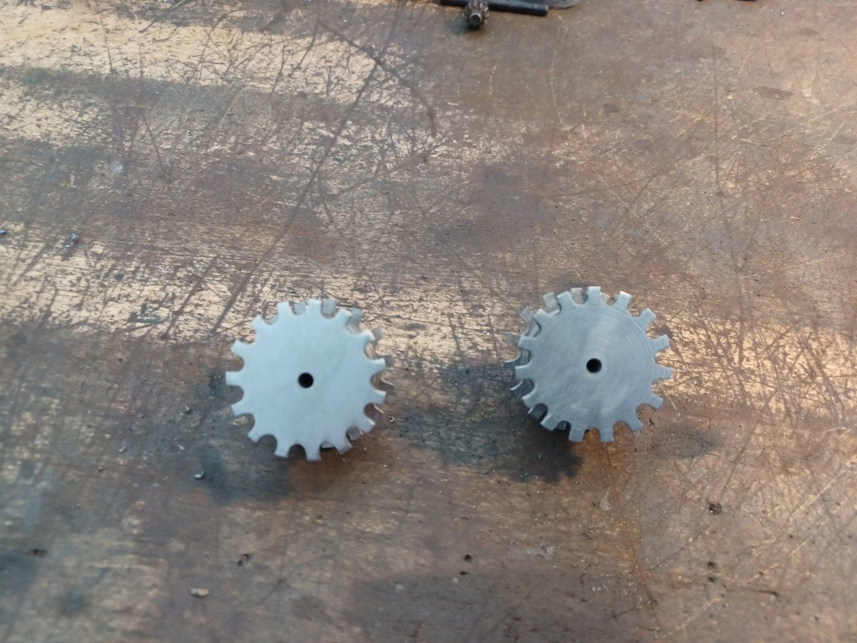
Then I finally got a method of drilling teh appropriate sized holes along a circle corresponding to the pitch circle diameter and opening out those holes with a burr mounted in the proxxon. A flap disk in the dremel served to smooth things out a bit.
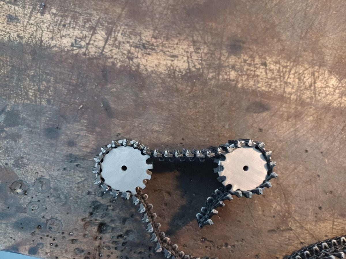
And the tracks fit very nicely indeed.
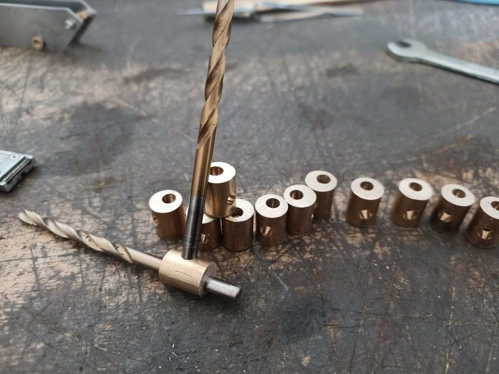
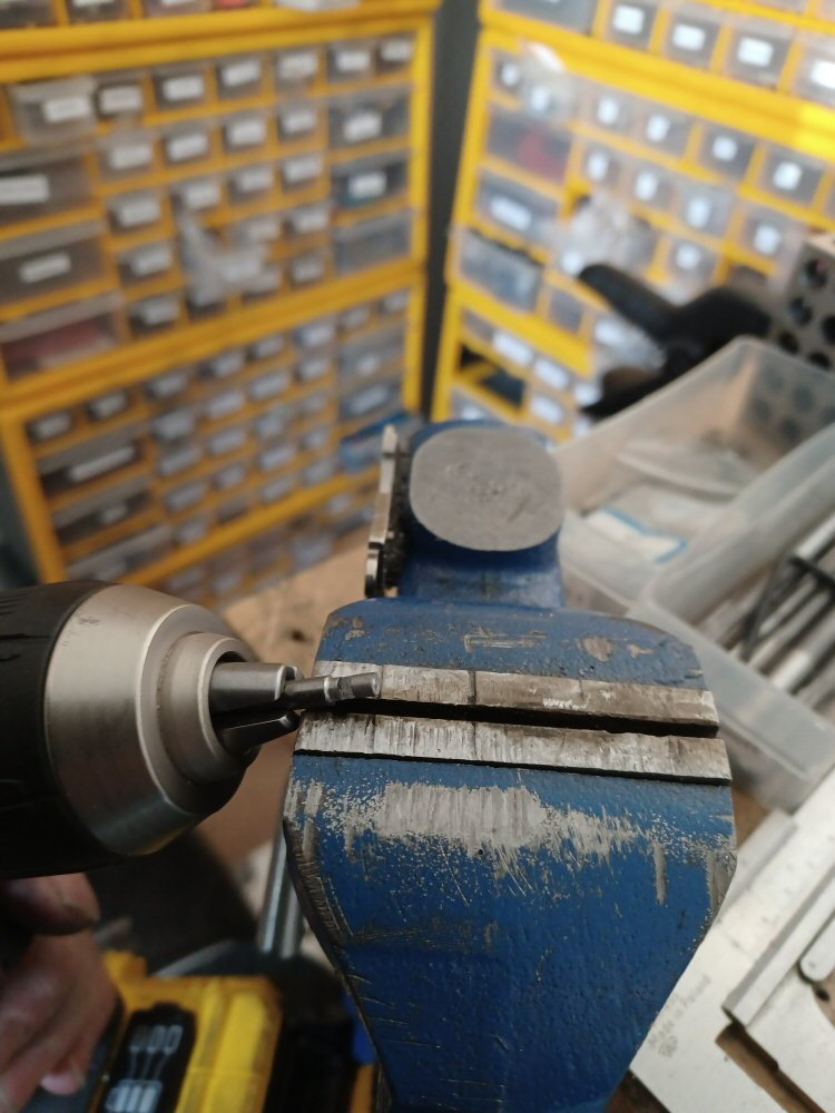
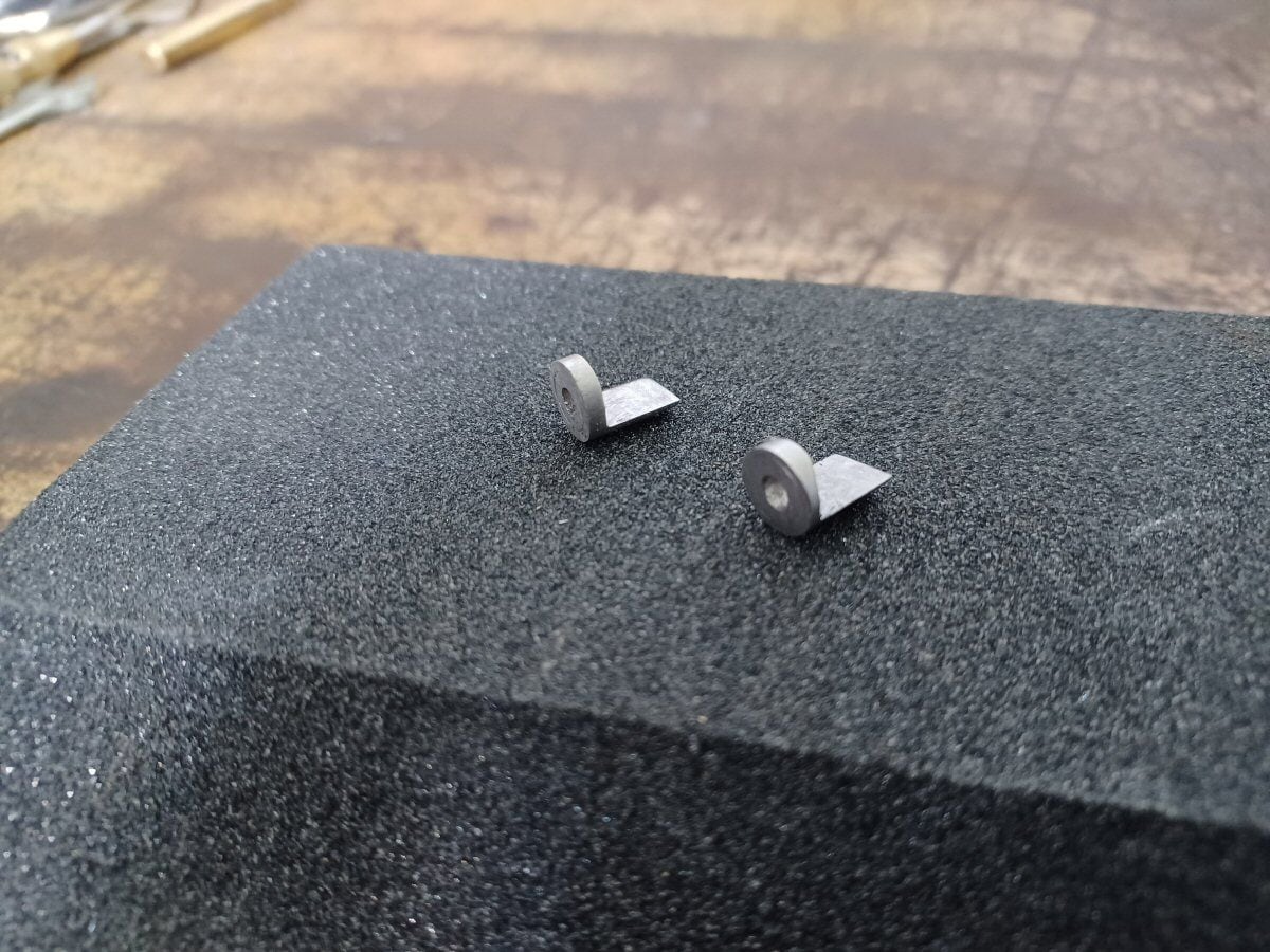
I then need a means of letting the axle engage with the sprocket. The simplest is a D shape on the central bore but I dont have broaches.
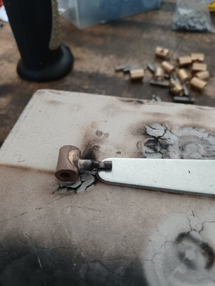
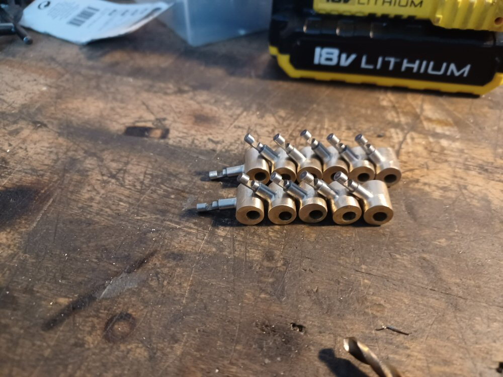
So I made some silver steel inserts like these:
When soldered into the bore of the sprocket then provide a D shape on the back.
This is what a flat on the drive shaft will enage with.
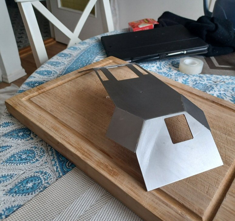
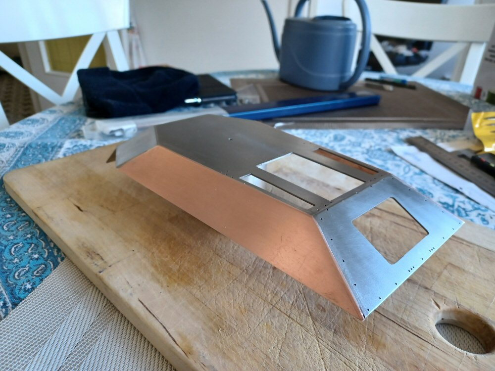
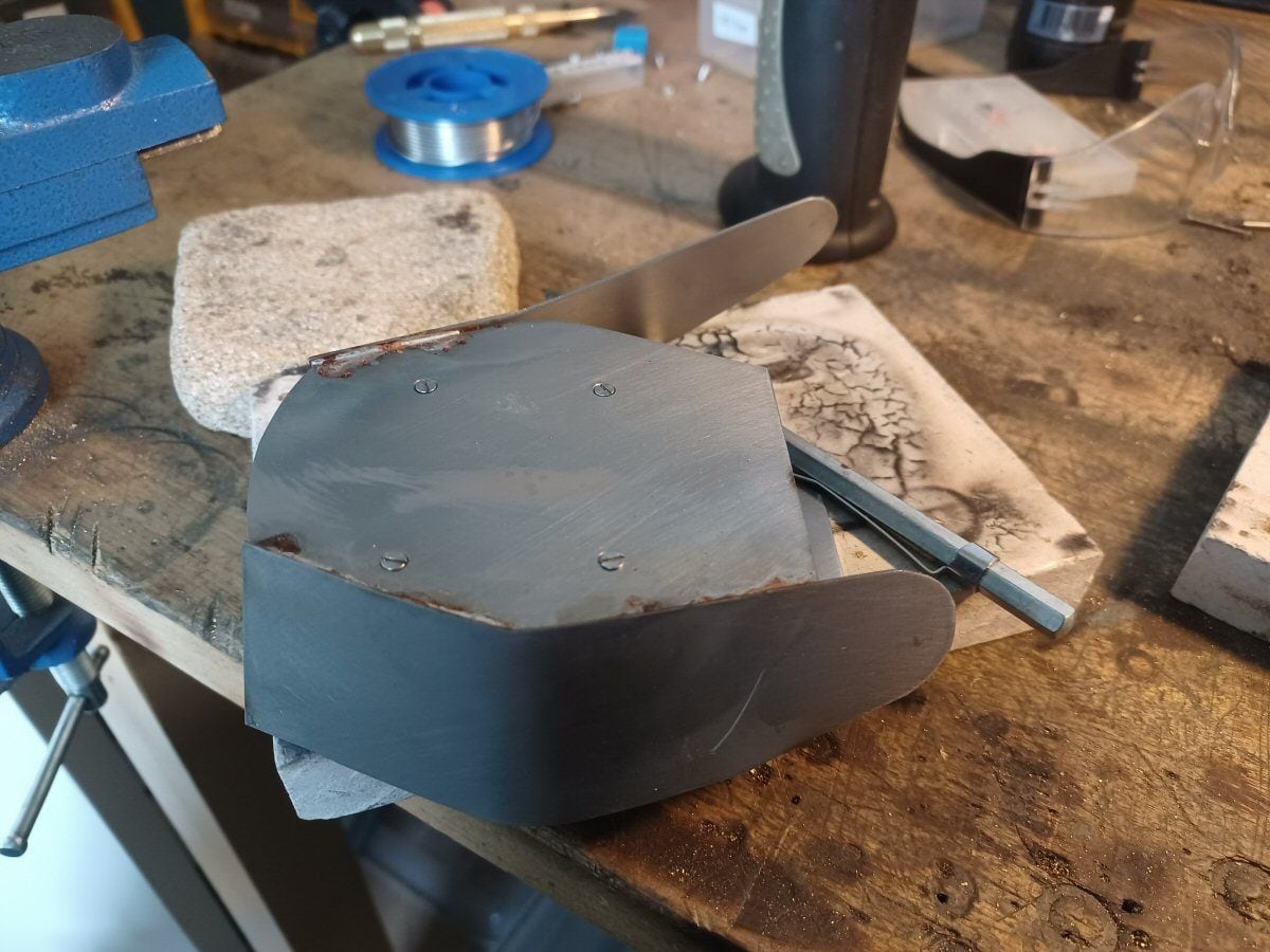
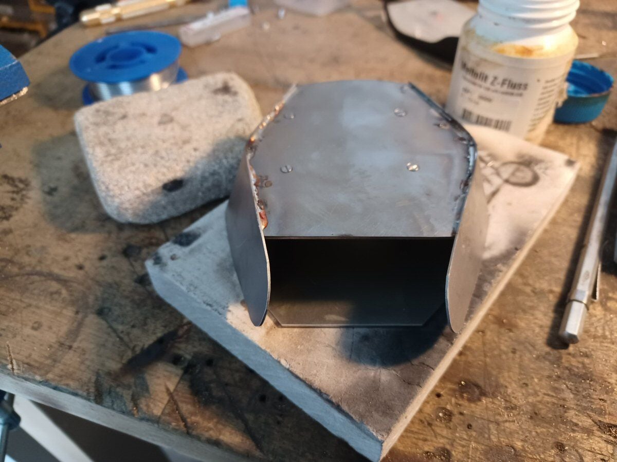
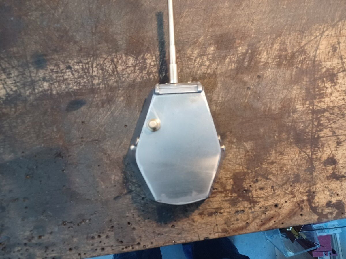
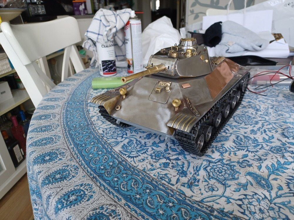
The turret was always going to a pig. I made some measurements and sketches and cut a bottom and top plate. These were joined together by some threaded bars to hold them in the right orientation. Then I simply “wrapped” steel sheet around this and soldered in place. Looks like a total badger but this is just the subframe.
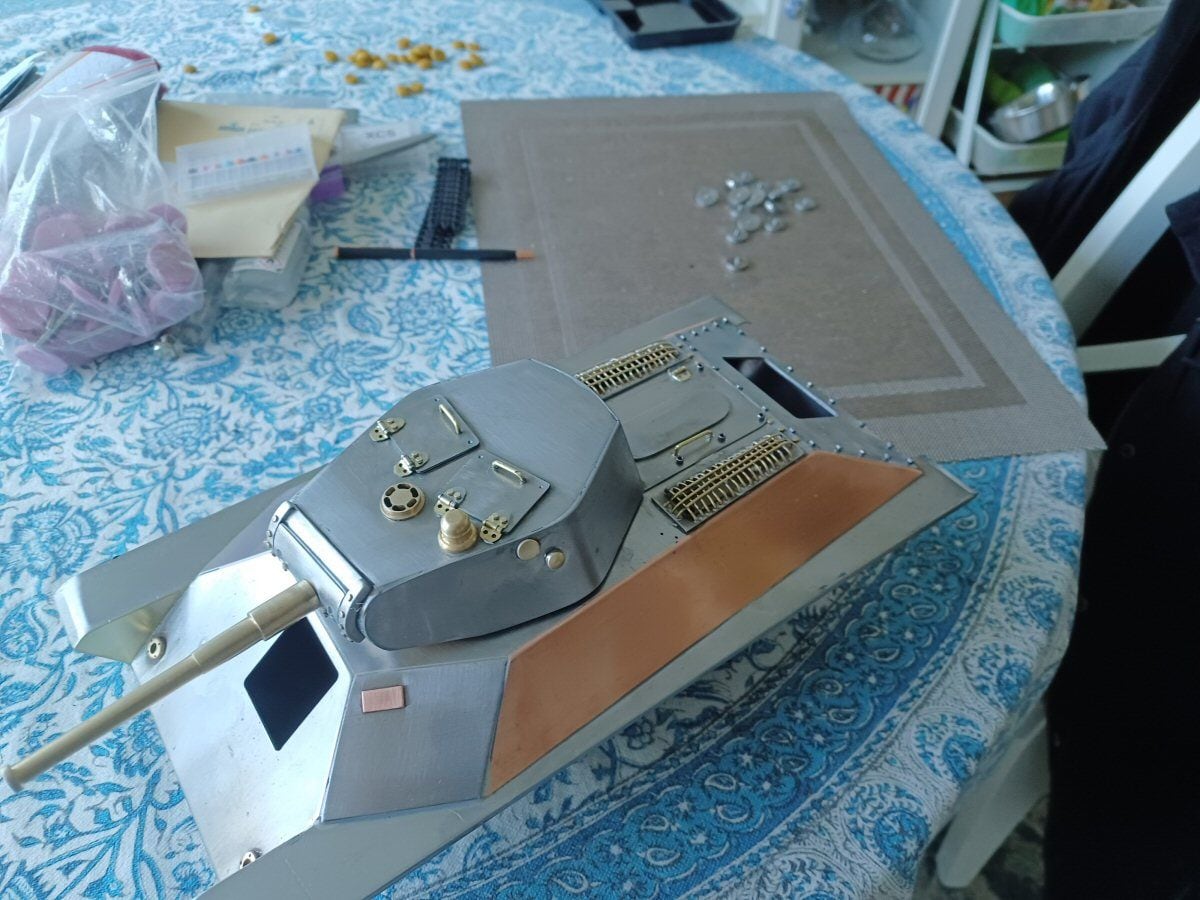
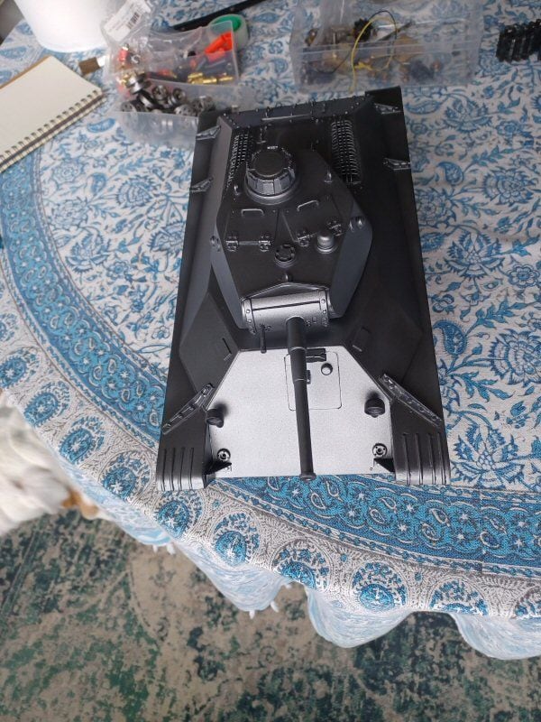
This is the turret with a new top plate on to hide some screws and a rudimentary mantlet and gun. I thibk the asymmetry has been reproduced enough to keep me happy at least.
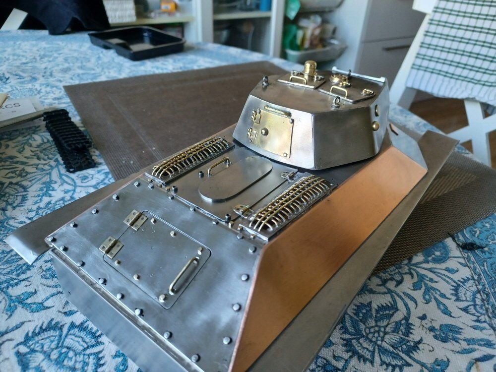
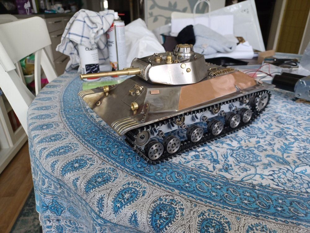
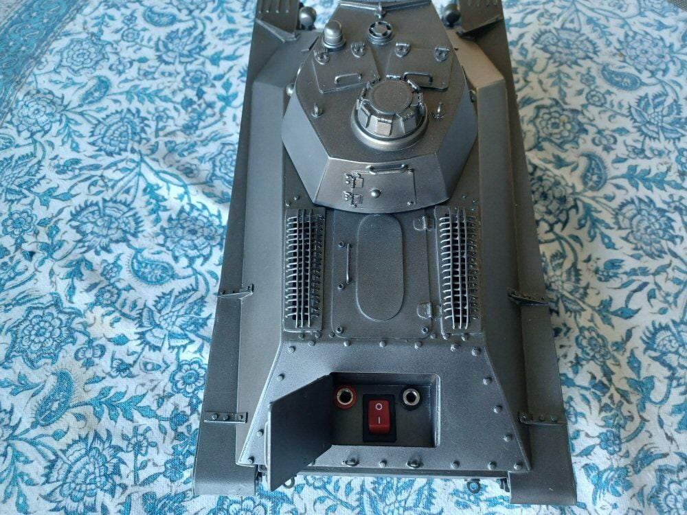
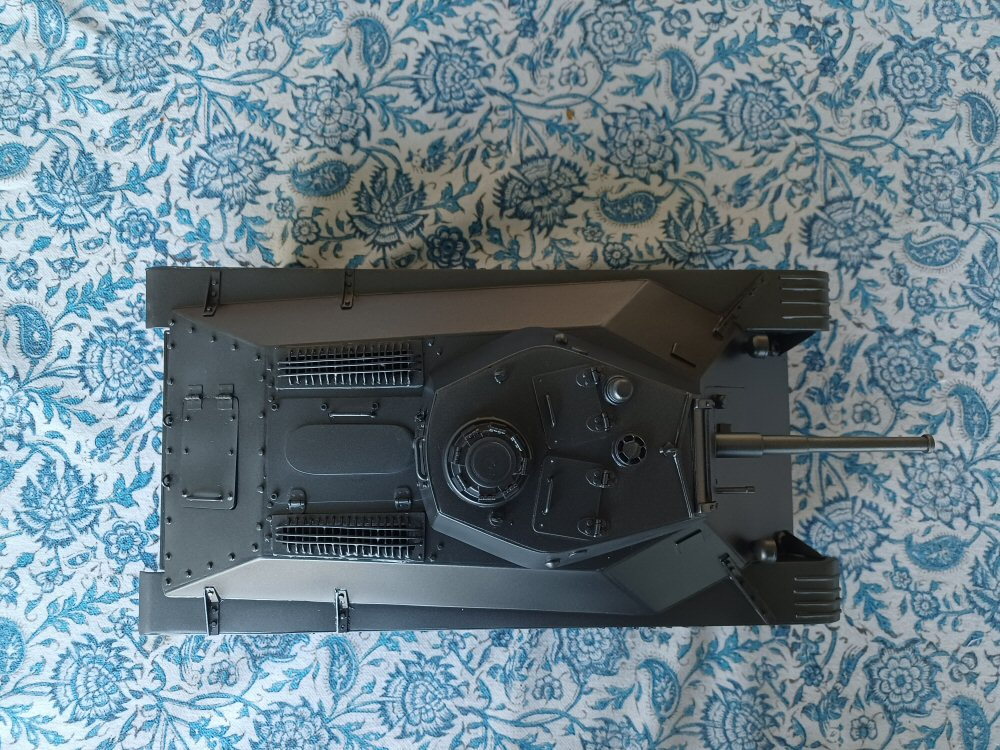
I then did some work on the body. The grilles on the vents of the engine deck seem to range from chicken wire to rebar depending on what pictures you look at but I used some brass bar and it will have to do as it was a pain in the rear.
Then I just started adding bits and pieces to try and flesh out the details. Not everything is accurate…but I don’t care at this point.
I cannot pretend to be machinist…Im a chemist by trade.
Ive thought of buying a lathe once or twice but I have neither the room or the skill for one.
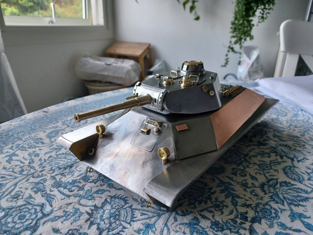
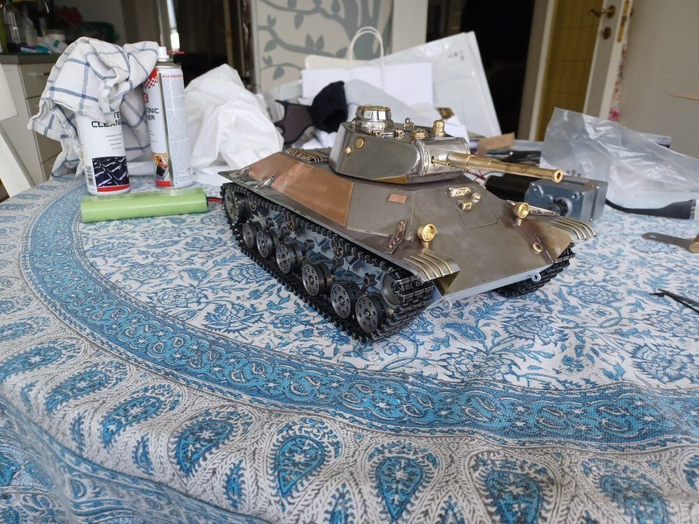
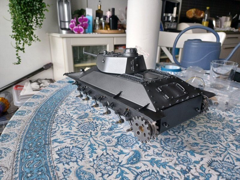
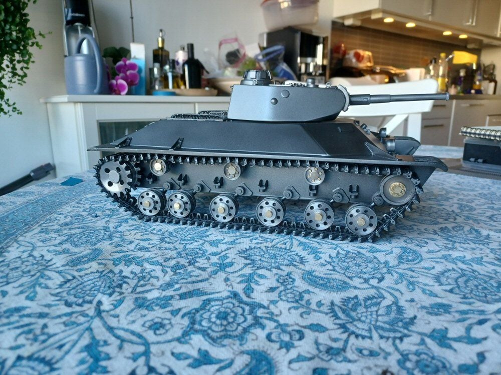
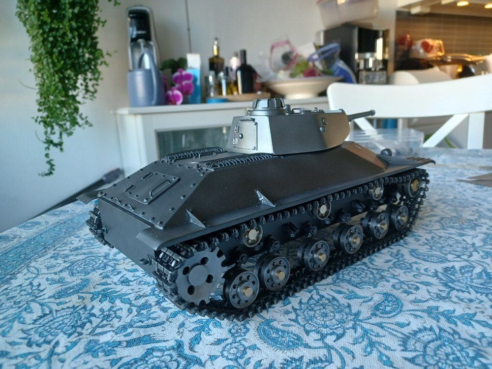
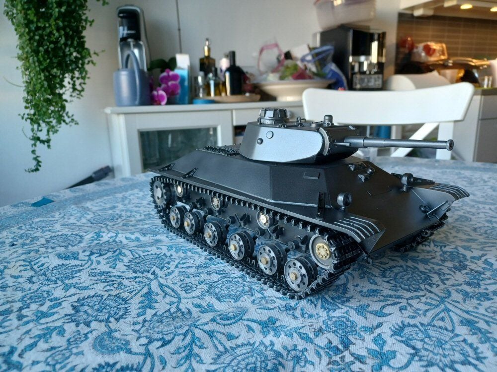
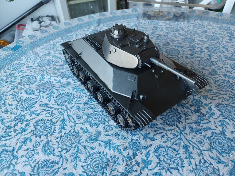
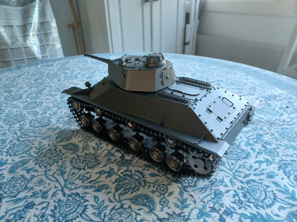
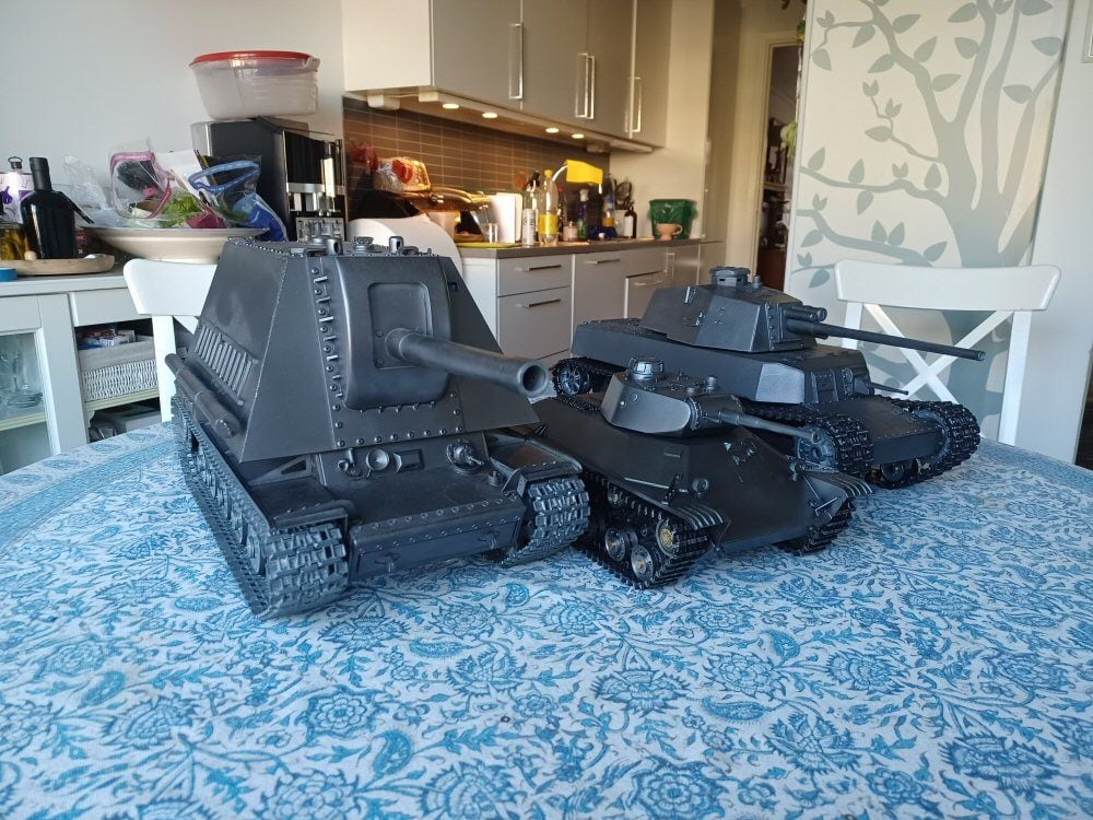
I test fitted some tracks today…some final bits to attach to the hull then its time for a scrub with a snading sponge and some acetone and then a coat of primer before final assembly.
Thanks for sharing this amazing build. It’s amazing what you have accomplished with simple hand tools and a small drill press. I’ve learned a lot looking at your creative solutions for building complex mechanical assemblies like the suspension system. Thanks again for sharing your skills with us and enjoy the rest of your build.
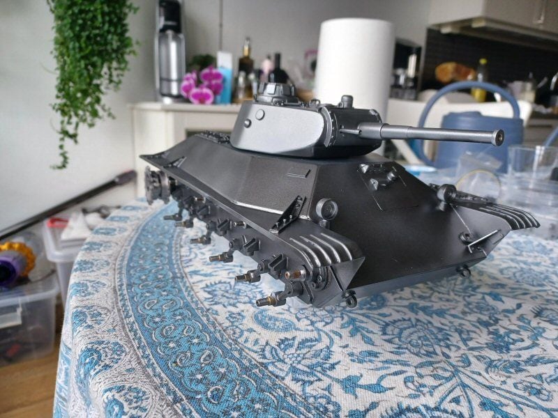
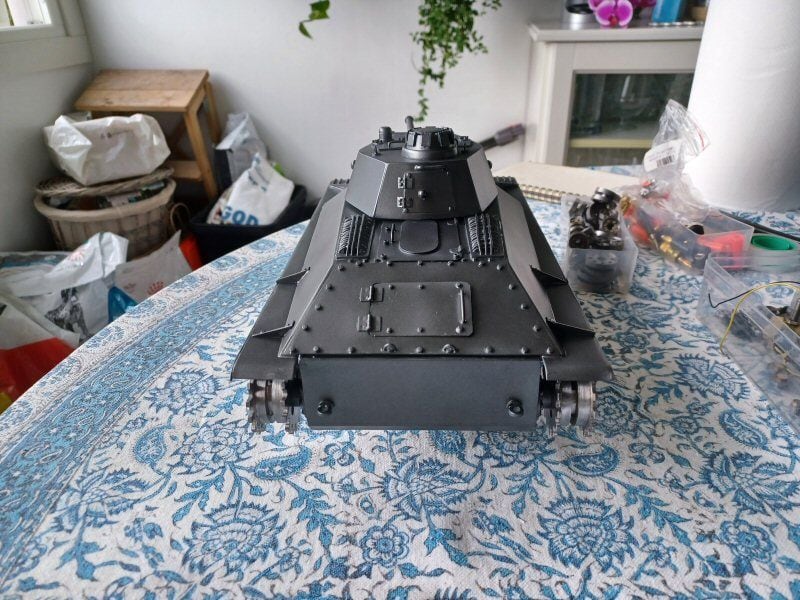
I dont like painting and it is only ever done to match other tanks I have and cover up scabby bodywork which was th ecircumstance here.
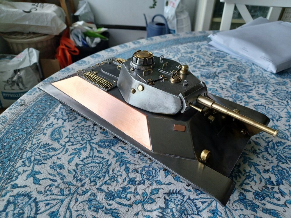
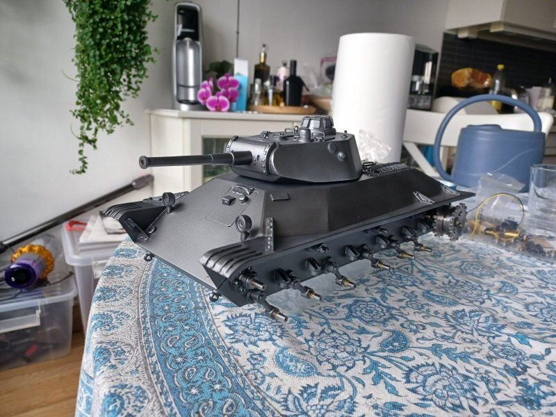
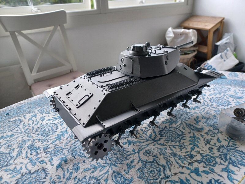
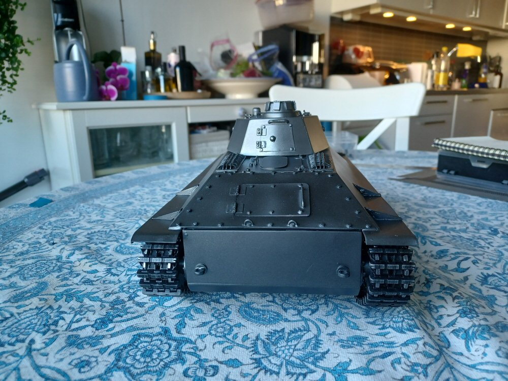
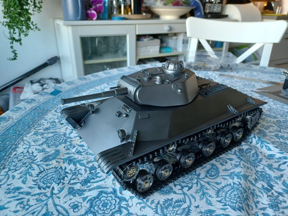
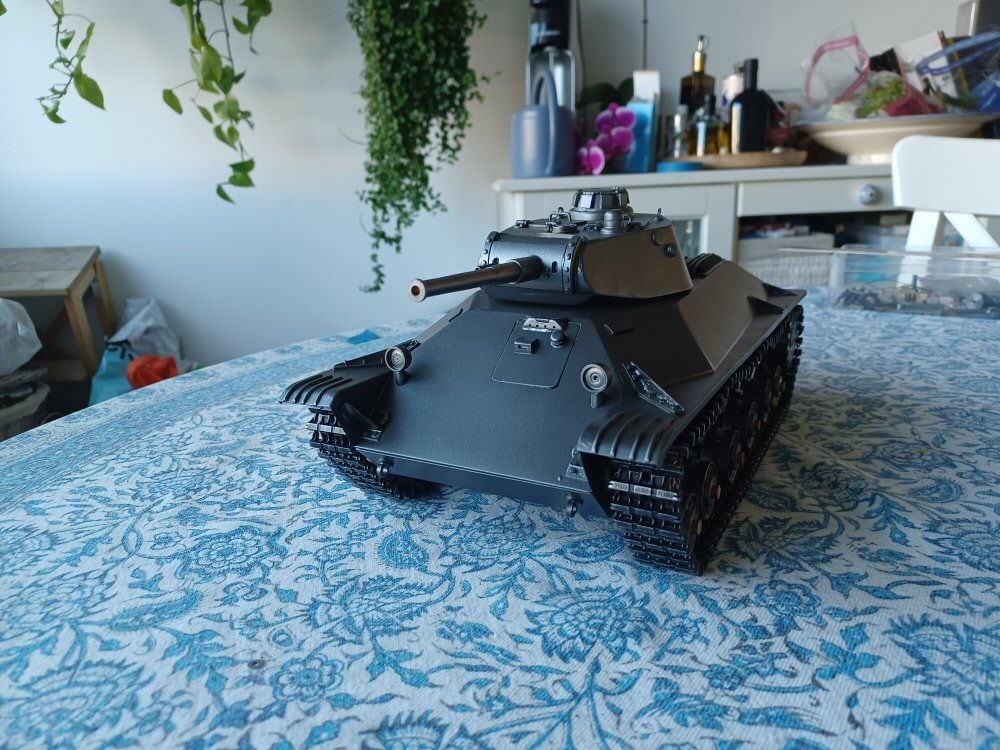
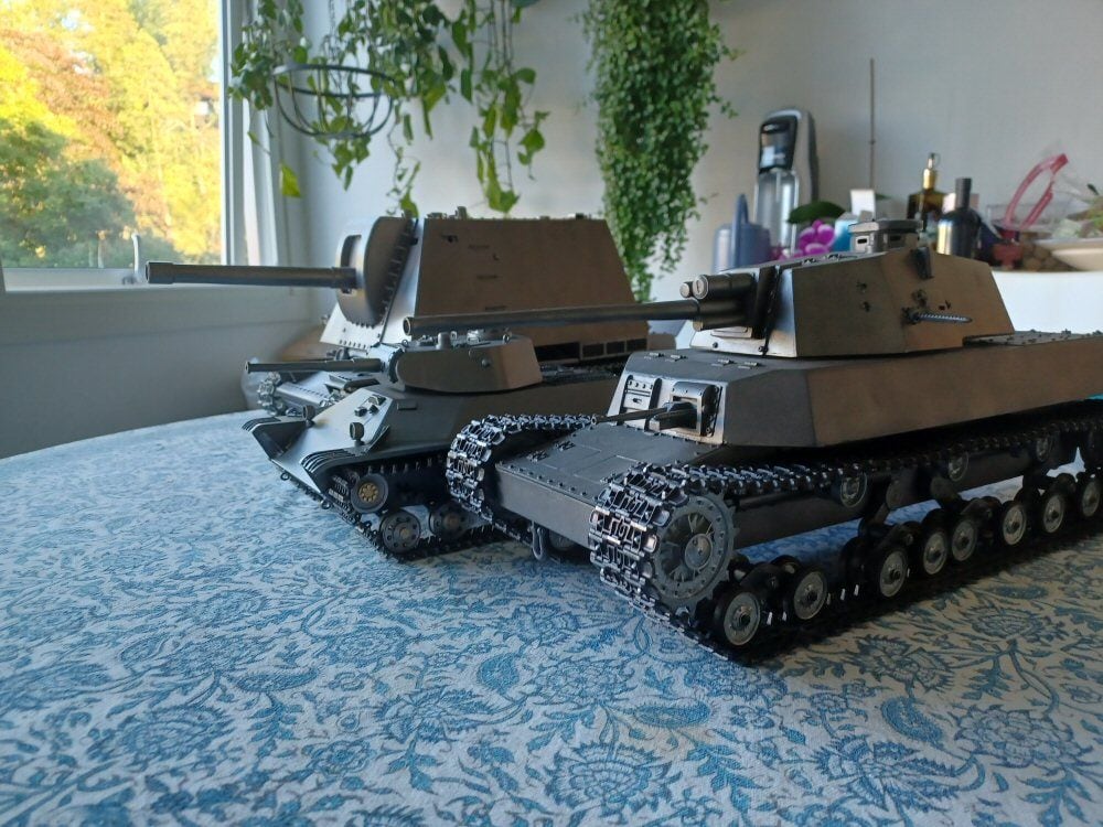
Primed it and sprayed on a few clumsy coats of gun metal paint then started putting it together.
No real issues there. Noticed a few mistakes underway but do not care in the slightest!
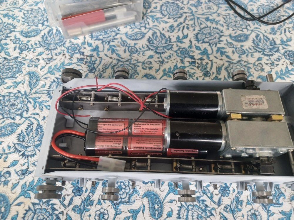
Motors went in fine, greased up the bearings as I went.
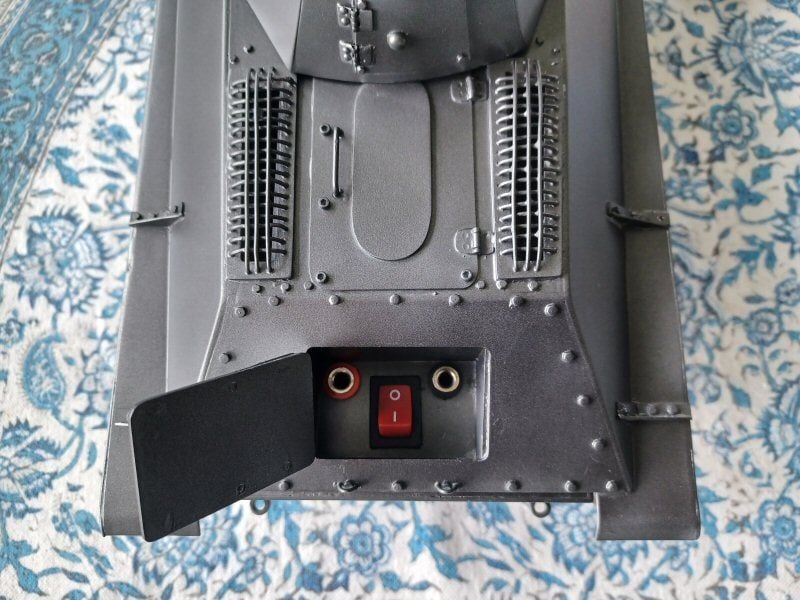
I dislike having to undo screws and such to charge batteries and so so I mounted a box under th erear hatch that just squeezes in between rear hull and motors. Into this I mounted a set of banana ports and a fairly high amp switch. I will wire these into the tank when I get around to the electrics I guess.
I have been avoiding the wheels as they lack hubcaps but that has to be done next and I am not sure how I will tackle those.
Thats coming along great. I realy like your charging posts. I will have to remember that setup. I have done alot of RC vehicles if you have questions just let me know.