I could not find this information anywhere so I decided to ask for help.
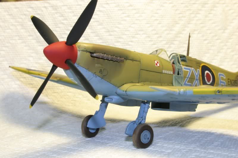
Currently I am working on Spitfire Mk IXc (early) and few questions arised regarding the location of brake lines on the main gear.
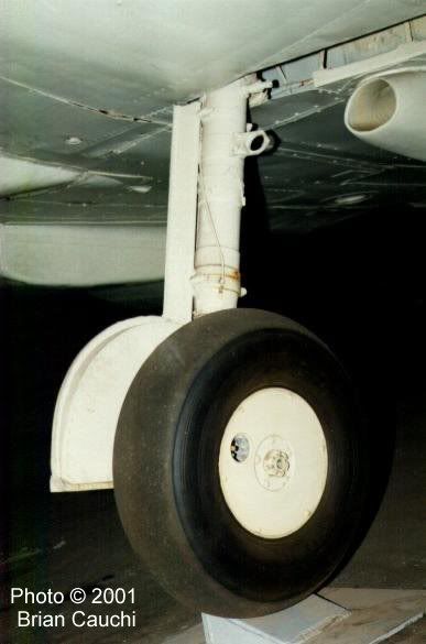
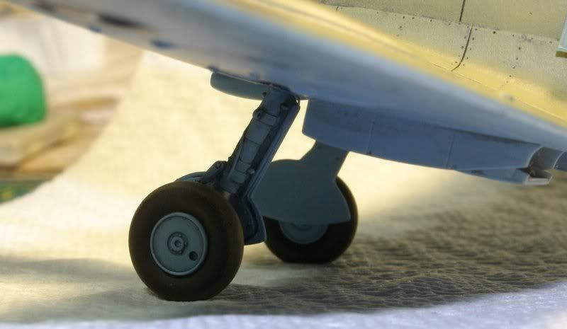
Some pictures show a “line” coming on a front side of a strut (what I think is not a brake line) and also a line located on a rear edge of a gear cover and flexible (black) hose bend on a rear side of a strut going to the wheel brake.
I believe the fronl “line” is some kind of locking mechanism, but I do not have any document explaing the landing gear mechanism structure. Any help in this matter is welcome and appreciated.
here are some picts showing the line some claim to be a brake line. I do not think it is a brake line but I have no proof of it. This picture does not show a rear side of thestrut, where the real brake line is located.
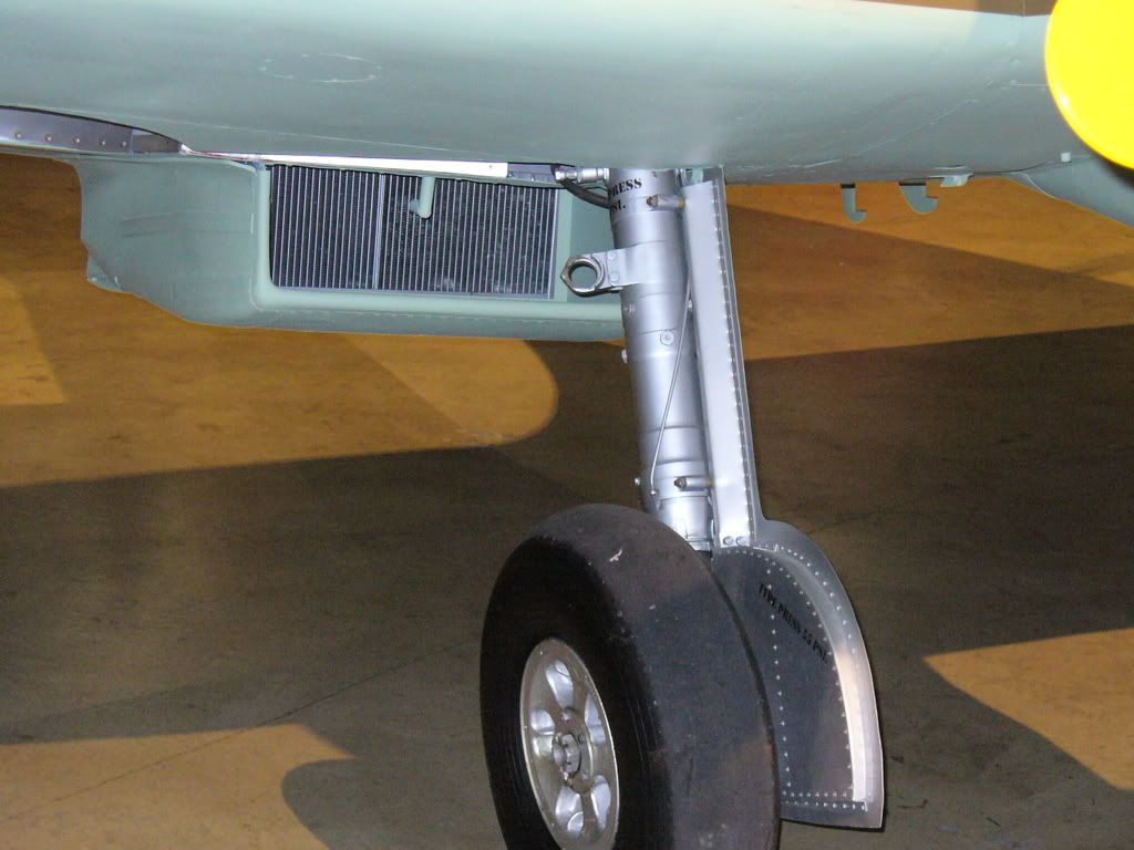
It look’s like the brake line is on the back side of the wheel door.
EDIT…The link doesnt work properly for what I wanted it to show
Go to walkarounds on top, then propeller walkarounds, scroll down to spitfire “spitfire MK XVI including engine photos”. It’s 3rd from the bottom in the spitfire section. There’s a pic of the right main leg where you can clearly see the brake line on the wheel door. It’s the best pic I could find that actually shows it. Sorry I couldnt get direct link.
thanks. It is almost right [:)]. Unfortunetely it is a rebuilt Spit and this line is not an original setting - unless you meant a diferent picture than shown.
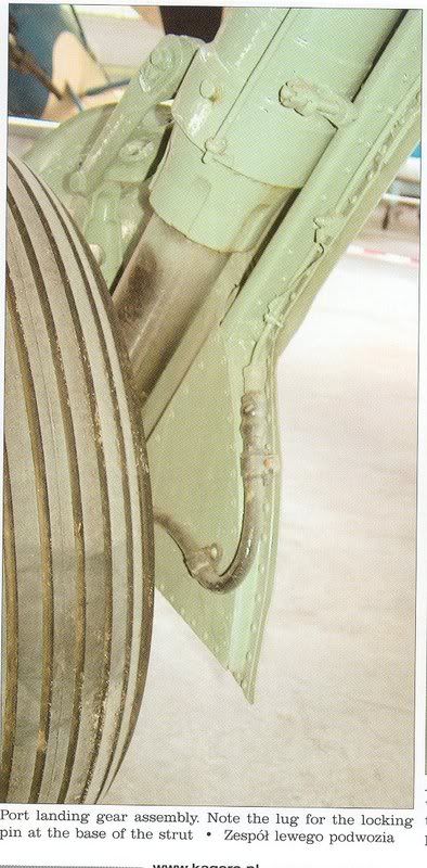
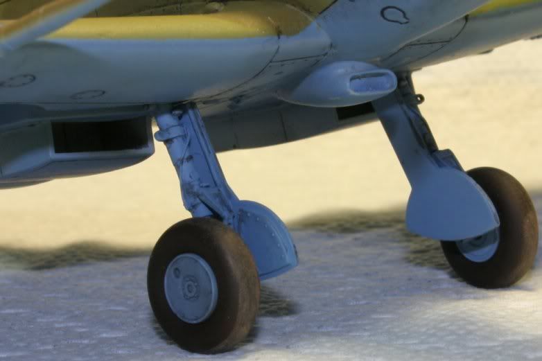
Kagero Top Shots shows this picture of a Landing Gear
and here the brake line is clearly visible and also shows the eng of the line in question. What is the other line ??
I’m not a big fan of using restored items as reference because I’ve seen too many that do not match what they looked like back in the day. Heres a pic of the spitfire I did a walk around. it’s from the USAF museum.
Thanks Stan ! You are absolutely right. Referenced restored aircraft may be tricky [:)].
In the meantime I think I resolved the issue with Spit langind gear.
The “line” shown on the picture above is in fact a locking rod, some kind of safety mechanism for the shock absorber. The brake line always was placed at the rear edge of the cover coming down to the wheel with a flexible (black) hose.
If anyone has more to add into it I appreciate your input.
BTW: I found one book where the locking rod is called a “brake line”, so be careful with the resource books as well and always recheck references [:)]
Ok, so the pic I posted is correct then? I just want to make sure if I was right or wrong, I know the modern restores can have inaccurucies but they can vary. So is the one I posted right?
No, I think the picture you found is wrong. The line shown there is placed on the inside surface of the cover (not at the edge) and it is made out of a single (probobly) flexible hose. In fact the original part was a steel pipe attached to the cover and connected with a wheel with a short flexible hose (black). The cover had some kind of undercut where the line was sitting safely attached with set of fasteners. If you compare the two picutrs you will see the diference in location.
Now, I guess, I’m going to ruin it, for you, sorry. The torque-link (then known as torsion link) u/c wasn’t introduced, on the IX, XI, XII & XIII, until September 1945, even though it was proposed in December, 1942. The VII & VIII had them from June, 1944.
Most newer restorations are as historically accurate as possible. My plane looks exactly as it did in Viet Nam. There are some exceptions, a second civilian radio replaced the FM radio, and the TACAN was removed in favor of a LORAN unit. These are flight safety improvements, and trump history, but as tech improves, I’ve replaced the Loran with a hand held GPS and plan to replace the tacan. Externally there are no differences otherwise.