Thanks all for your interest. Much appreciated.
Happy modeling Crackers [;)][:)]
Thanks all for your interest. Much appreciated.
Happy modeling Crackers [;)][:)]
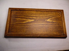
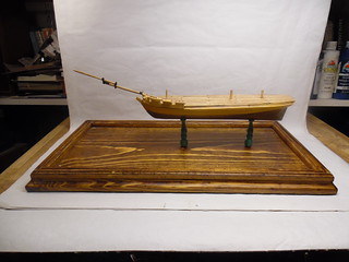
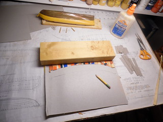
Now that the PELICAN hull has been completed, it’s time to think about mounting the model. Adding deck furniture, masting and rigging will come later. This is critical, because if I were to add these components now, they would be damaged while fumbling the hull trying to secure ther model on the base. On the right panel, a cardboard deck template has been placed on the wooden base bottom with plenty of room for the additional bowsprit. This will indicate just where the model is to be secured. This same template will be used to position the deck furniture in the correct order. All I do is mark the spot on the deck with a pencil, then glue the correct furniture on that spot. The “frame” around the base bottom is slotted to receive future glass panels as a display case.
Now, I propose to have some fun, which might freak out model purists with cardiac arrest. I have been considering making a mini-diorama, by adhearing fine sand on the bottom of the display case, then adding small sea creatures, such as sharks, fishes, an octopus and sea shells. Above this will be a simulated sea with a couple of leaping porpoises ahead of the PELICAN that will be secured to this pseudo sea. Is this proposal whakco or what ? Maybe some input to this idea.
To be continued. Happy modeling. Crackers [:(][:D]
I very much like the idea … having a display in which diorama and wood base are kind of mixed will be a very decorative thing. I think that is the weakest point on many dio´s… how to “cover” the miniature-worlds “end” and how to “start” with real world.
To not at all cover it and haveing the “change of world” as a kind of natural thing will be interesting.
The question: who to simulate the sea? Only a thin surface? Will be tricky to keep it in place, have the right surface and not having it too thick.
Or generating the hole “block” of water from the bottom of the sea until its surface? … then how to generate the sides … straight and clear as in a fish tank? …
I am looking forward to this! Very much like the idea!
Watching also. I like building wood boats and ships.
EJ
I have never seen anyone scratch build a ship before ., this is so educational ., please keep them coming , enjoying every single addition .
Crackers,
Threads like yours are invaluable to me. I learn a lot from many people on this site and your scratch building WIP is no exception. We’re watching!!
Mike
Watching your build closely. My avatar was a plank on bulkhead kit. Love wooden ships. You are doing a great job on your build. Keep up the great work.
Jim [cptn]
Sorry for the delay in upgrading my thread. Been out of town and required to complete some honey-do projects around the house.
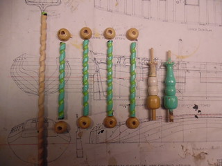
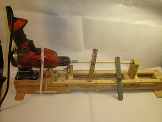
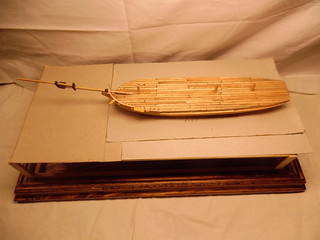
On the top panel, are two small model supports made out of beads that will hold the hull in place on ther surface of the display case base. Next to these supports are four dowels carved in a spiral configuration to support the sea diorama. Carving these spirals on dowels required a study hand on my home made lathe powered by an electric drill. A gouging head was chucked into my Dremel MotorTool and applied to the rotating dowel on the lathe. Moving the Dremel slowly with my right hand in a study slow motion, a spiral was carved into the dowel. After several disappointing tryouts, my task was finally accomplished.
These supports were then painted with acrylic sea green to match the proposed aquarium environment beneath the model.
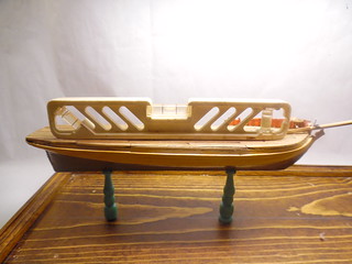
Holes were drilled on the center of the display base for the beaded supports, top panel. To make sure the model hull is on a true horizontal position with the model base, a carpenter’s leveler was placed on the model deck. The bubble found the exact center.
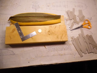
After the hull has be situated in place, it is time to consider making a template of the sea surface that will surround the hull water line.
The hull was turned up-side down. A scrap block of wood was placed next the the hull, as seen at left. Thin scaps of wood were placed under the larger wood block until the top surface on the block of wood was on the same height as the model water line. A metal right angle square was positioned around the hull to make sure the model water line agreed with the block of wood top surface.
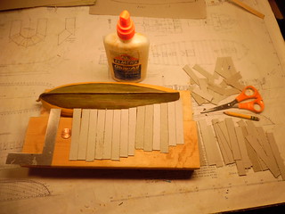
Next, long rectangular strips of cardboard were cut out with scissors. On one end of this strip was trimed to conform with the model water line, then glued onto the wood block. This task continued until both port and starboard water lines were covered, as seen on the right panel.
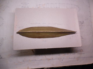
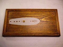
When all the card board strips were aligned with the model water line and glued, the wood block was flipped up-side-down and placed on a fresh card board surface where both port and starboard sections edges were traced with a pencil. The water line profile was cut out with a pair of scissors, then placed on the upturned surface as a water line template for the future clear plastic sheet that will become the diorama sea.
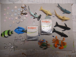
Here is the completed card board template that will be the future clear plastic sea. This template is supported by the four spiral supports seen earlier. When this sea is completed, the “aquarium” sea life will be displayed under the surface. Shopping at Michael’s craft store, my wife selected these denizens of the deep. Granted, they are all over scale in size. If these creatures were in correct scale, they would be too small to be seen. The Sculpey polymer clay will be used to create an octopus and a sting ray, plus other small fishes.
To be continued.
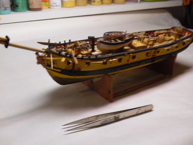
Hi folks, I’m back again. Just about a year ago, I started the thread on scratch building, the British sloop-of -war, HMS PELICAN, the ex-French privateer, FREDRICK captured by the British in 1781 and payed out of service in 1784 at the conclusion with the war with France. The model is based on the plans of the late Harold Hahn. I got bored with the project and just now decided to return to the Forum.
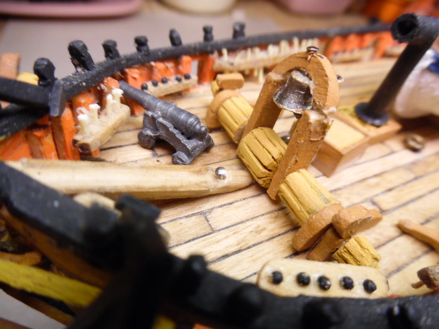
All the deck furniture is NOT secured in place. The guns and other deck gear is just for show and tell for this thread. They will be removed so that my fingers can belay the rigging lines to their respective places on the belaying racks. From past experience, deck furniture only impeded the rigging task.
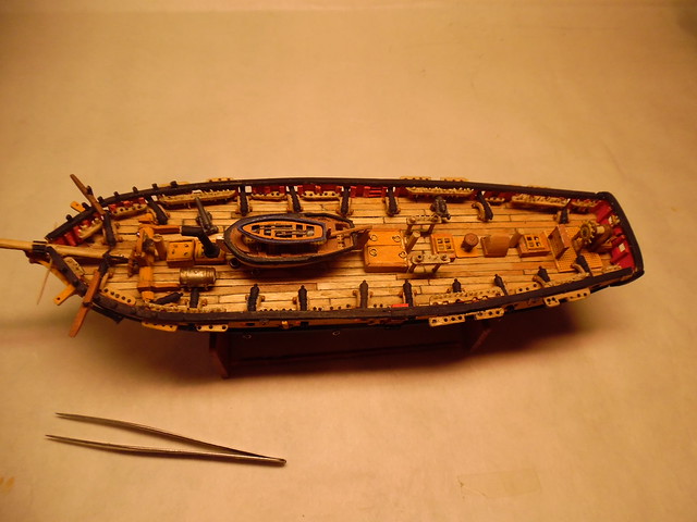
Closer detail of the mid-section of the PELICAN deck The gun tackler will not be rigged in place. My fingers just do not have the ability to complete this task.
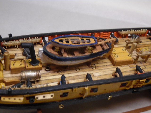
Close detail of the stern section. The capstan is that dark brown dot on the deck in the center of the picture. A skylight is on the left side of the capstan, while a companion way is on the right side of the capstan. This is the arrangement as shown on the Harold Hahn plans. When it came time to insert ther capstan bars in place and have the crew heave on the capstan to haul in a rope, how could this be accomplished with a skylight and companion way in place ? Would the crew have to have long legs to step over these structures ? Inquiring minds want to know.
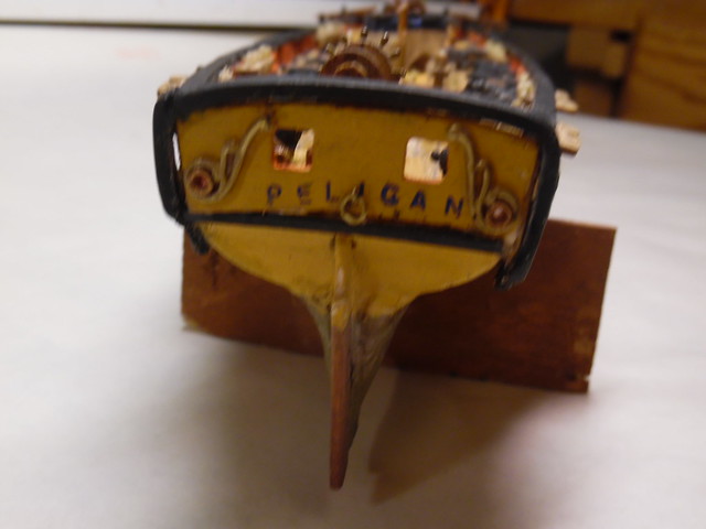
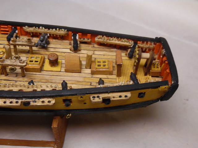
Stern detain of the PELICAN. The ship’s name was accomplished with transfer letters that are rubbed into place at the end of a blunt dowel. The ring by the letter “I” on the PELICAN, is a ring to tow the ship’s launch during battle. During engagement, the ships boat, or boats were often towed behind the warship, so that the boats would not be damaged during the heat of battle.
Bow detail of the PELICAN. The windlass is not my best work. I had to struggle to make it as it is. The bell is from an eyelet of an old boot that had to be pounded and shaped into place. The deck flooring are popsicle sticks cut to size with simulated tar caulking by rubbing a black felt tip marker along the edge.
My next entry on this thread will be on how the model arrived with details on this present stage.
Happy modeling Crackers [*-)]
Wonderful.
Ay !
Quite criticsizing yourself . I see a lot of work that says you are driven . Now that said I have to remind you .On your case , 3 to 4 inches on each end and 1 to 2 inches from any Yardarm tips .
Oh , keep on keeping on , I love it .
Great work! [t$t] Thoroughly enjoying this build. Learned a lot so far and looking forward to learning a lot more.
Jim [cptn]
Thanks guys for your support. Appreciate your good input. As this thread is continued, the dialog will focus on how the completed hull was achieved to the stage where the rigging process will begin.
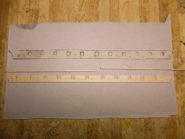
When the deck of the hull was completed, the next step would be to add the bulwark with the gunports. Cutting out this section would be impossible on wood, as the wood would splinter. Thus, sections of the bulwark would have to be cut and glued together like a puzzle, as is shown in the above picture. Before creating this bulwark from wood, a cardboard template was made on a trial run on the hull to see that the bulwark is a correct fit. The cardboard template is above the wooden template section.
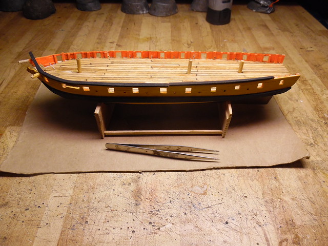
The completed port and starboard bulwarks are in place. The holes between the gunports are for the insurtion of rowing sweeps on the real ship, to be used in calm weather.
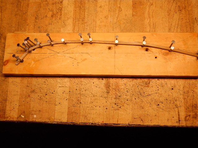
When the bulwarks are in place, the next task is to make the black cap rail that goes on top of the bulwark. A piece of scap wood is needed. The overhead profile of both the port and starboard side of the hull is drawn on the scrap wood. Penny nails are inserted along this line that is the correct width of the cap rail. Thin stips of wood that will bne the cap rail are soaked in hotwater with a touch of bleach. When this wood is completely soaked and plyable, it is VERY carefull bent between the nails and dried overnight. When the desired shaope of the cap rail is achieved after drying, it is painted with black acrylic and glued into place on top of the bulwark.
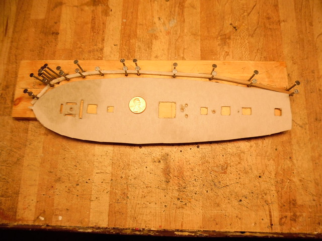
This is a closer view of the procedure outlined above. Perhaps this is a better explaination. The hull profile in cardboard with the penny coin for scale.
Here, the cap rail is glued in place on the port side of the model. To be continued.
Happy modeling Crackers [8-)][Y]
Glad the PELICAN is back and really enjoyed the wood bending class. Before we get too far, I noticed the varied cannons. Did you scratch build some of those?
Jack
According to the smart people, the fundamental answer is that you had enough men on enough bars to be able to let loose when there was a deck obstruction.
But, also remember that such things as sompanionways were built of panels that were just pegged to the ship, they could be struck down to clear the capstan. Ditto the skylight. Gratings to fill the holes was probably lashed up under the overhead below decks.
A windlas is similar, there’s only about a 45º arc that the windlas bars can be heaved through, since you need room to pul them out before they touch the deck to be passed forward again.
The capstan was clearly superior to the windlass, as it could be “run” in either direct by merely reversing the pawl. However, it was manpower intensive. Slightly faster, too. A windlass usually could only be worked by four men pulling, and having a mate to mind the pawl, and boys to pass the bars.

Thank you CapnMac82 on your explanation of the position of the capstan on the PELICAN model. On this warship model by Dan Holmes, the capstan is visable without protuding deck furniture obstruction. The grating can be walked on as long as crew members did not stub their toes as they trod across this deck feature. Ship builders were practicable people by constructing common sense things, especially on warships, where efficiency was a necessity, especially during battle. When viewing the Harold Hahn plans of the PELICAN, the skylight and the companion way somehow did not seen logical as obstruction to the crew working the capstan. I was tempted to remove these obstacles, but decided to remain true to the Hahn plans. Any comment on this question ?
Happy modeling Crackers [:|] [2cnts]
Carving the PELICAN’s launch and rowboat took some carving skills from a block of wood.
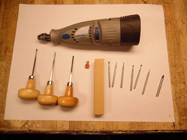
These are the tools that were needed for the carving procedure. Ising the elongated stick, a pencil drawing was made on the stick the basic outline of the craft, as noted on the Hahn plans. Most of the hollowing out of the boat was accomplished with my cordless Dremel drill aided with wood carving gouges.
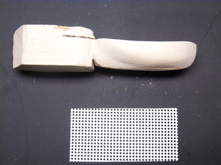
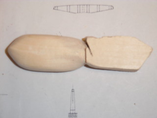
Here is the PELICAN launch from the side view and the bottom view. The extra piece of wood attached to the stern of the launch is a holding grip that was held while carving the vessel. The Dremel drill with carving attachments did most of the carving work.
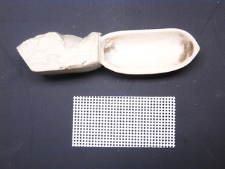
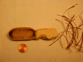
The top view of the launch. The right hand side of the picture is the paper ribs with a 10 mesh plastic canvas grating for the floor bottom of the launch. The penny denotes the scale of the carved launch.
 l
l
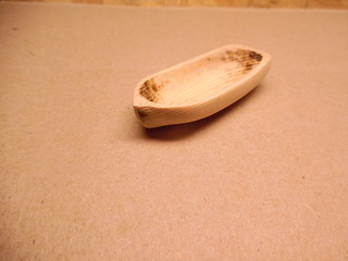
The hollowed out launch to be and the completed version at right. The penney is for scale.
The completed launch with the attached rowboat. The rowboat was the more difficult task, because of its small size after three attempts of carving. The determination of the depth of carving on both crafts was by holding the carving close to a naked light bulb. The brighter of the light shine through the carving indicated how close it would be to puncture through the wood.
To be continued.
Happy modeling Crackers [H]
Wondering who you are posting your images with. A click on image properties brings up a URL with staticflicker. Can you tell us more?
Thanks Don for your reply. I take pictures with my Samson digital camera. Transfer the images to flicker gallery, where it is placed on the Finescale Modeler Furum.
Happy modeling Crackers [:O]
The name PELICAN on the stern of the ship. The ring under the letter “I” is for towing the ship’s boat during battle, so that the vessel will not be shot to pieces, or the crew will have an escape craft should the PELICAN be in a sinking condition. The scroll work is made by squeezing very soft and malleable wire under a vice. It took a number of frustrating tries before the desired results were accomplished.
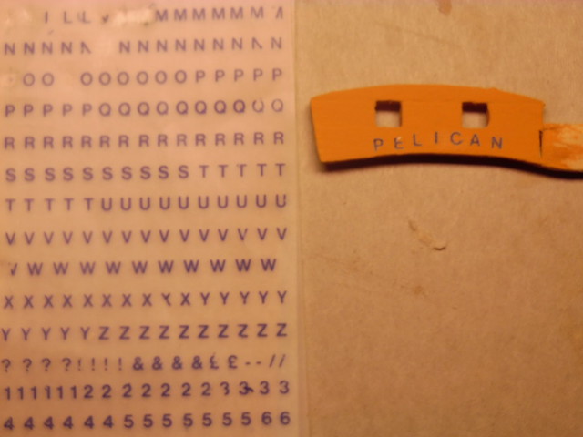
The name PELICAN was set by 1/8th" size transfer letters, which I happend to find at a stationery store years ago. I do not know where to find this size lettering here locally.The transfer is accomplished by placing the desired letter over the intended surface and rubbing that letter with a blunt pointed dowl. Scrubbing has to be very thorough, or else parts of the intended letter will come up missing.
Happy modeling Crackers [:P]