Thank you! ![]()
Anyway, I published all my know-how in this guide, so you can easily adapt my methods!
Thank you! ![]()
Anyway, I published all my know-how in this guide, so you can easily adapt my methods!
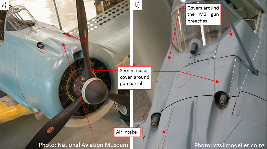
SBD Dauntless had a radial engine hidden under typical NACA cowling. The Douglas designers placed its carburetor air intake on the top of this cowling, and the two Browning M2 guns behind it. In the result, the upper part of the SBD fuselage, up to the pilot’s windscreen, had a quite complex shape:
I am sure that I will tweak this shape multiple times before I reach the most probable compromise between all the reference photos I have. It will be much easier to do it by modifying a simple mesh instead of the complex topologies of the final cowling. Thus I decided to create first a simpler version of this fuselage section and adjust it to the all of the available photos. I will describe this process in this and the next post. Once this shape “stabilizes”, I will use it as the 3D reference in forming the ultimate cowling. Because I am going to recreate all the internal details of the engine compartment, I will create each cowling panel as a separate object.
I started by creating the three key contours of the NACA cowling:
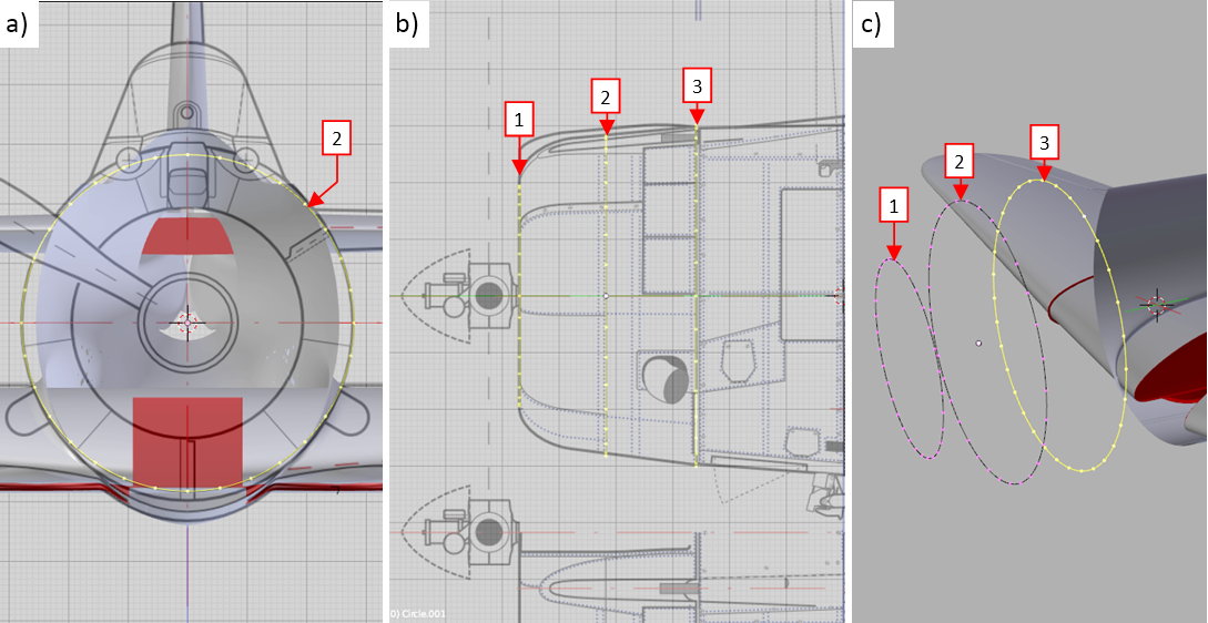
Section 1 (see figure “b”, above) was a perfect circle, while section 2 was a little bit higher than wider (see figure “a”, above). Ultimately section 3 was a regular ellipse. Note that all these sections have the same number of the vertices (32).
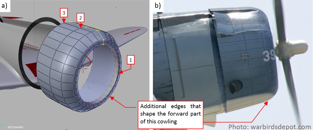
Once I created these three edges, I connected them using three arrays of faces. Them I added in between (using the Loop Cut command) three additional edge loops. I needed them to form the curved forward part of this cowling:
As you can see above, I fit the silhouette of this NACA cowling to the reference photos. This is a photo of the SBD-5, so I moved this cowling forward by 3.5” (see in this post about differences between SBD-3 and SBD-5 cowlings Figure 4-6, for the explanation).
When I finished the NACA cowling, I formed the basic shape of the next fuselage section:
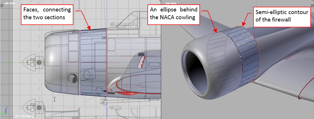
I created this part in the same way as the previous one. First I copied and shrunk the last NACA cowling edge, creating the gap for the outgoing air. Then I copied the firewall edge, and joined these two edges by an array of new faces.
In the next step I extruded the upper part of this surface, creating the section below the windscreen:
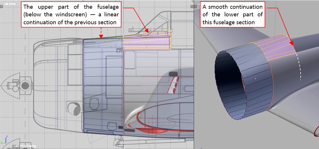
It is a “linear” continuation of the previous fuselage segment. I fitted its sides to the mid-fuselage, which I formed some months ago.
The next elements are the “bulges” that covered breeches of the Browning M2 guns. In this ‘quick and dirty’ approximation I formed them from a separate mesh patch (see figure “c”, below):
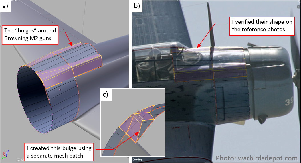
Of course, I verified their shape on the available photos, as you can see in figure “c”, above.
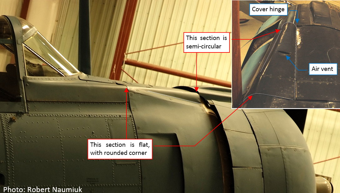
This comparison revealed, that the intersection lines between these “bulges” and the main fuselage require some improvements: they have to resemble straight lines:
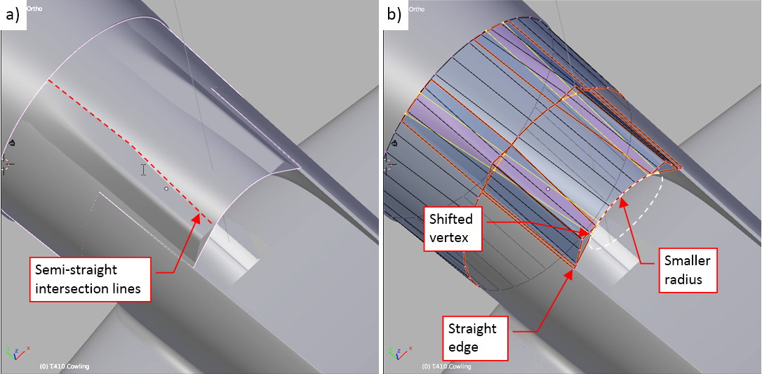
To obtain such an effect, I had to decrease the upper radius of the last bulkhead (figure “b”, above). In such a simple mesh it required just to move a few vertices. If I had to perform such an operation on the final panels, it would be much more difficult!
In the front of the gun barrels there were long recesses in the NACA cowling. The outer edges of such a feature are always a tough test for the model, because they depend on the proper shape of the both intersecting elements. First of these objects is the NACA cowling, the second is the shape of this recess — a cylinder in this case:
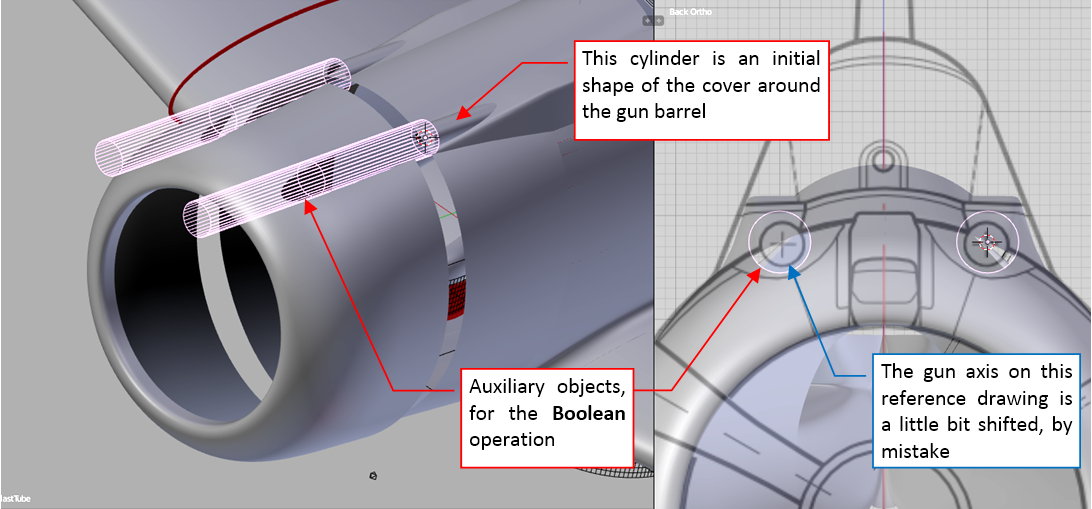
I cut these openings using a Boolean modifier. Figure below shows the result:
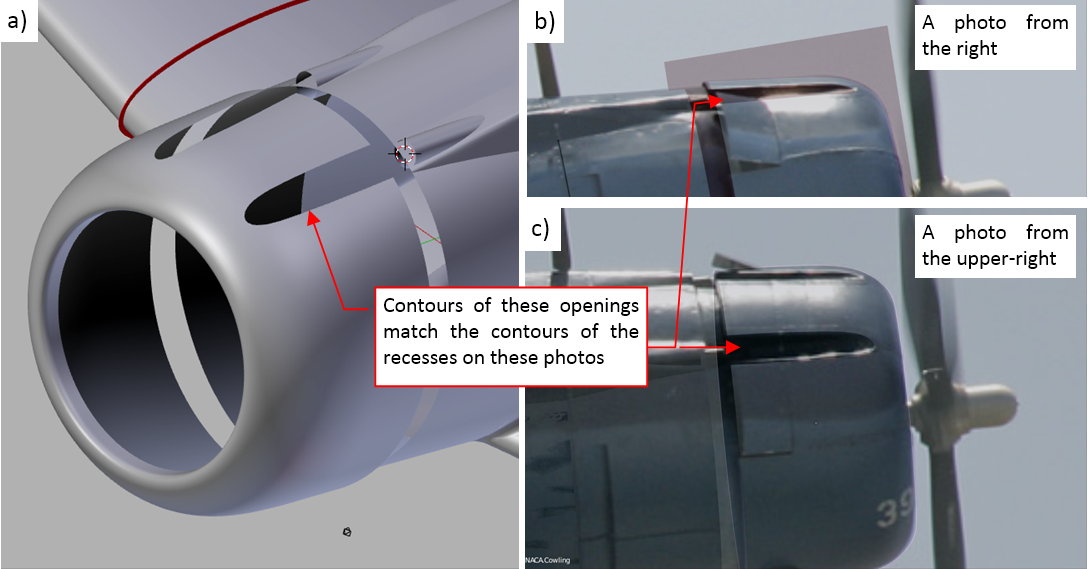
In figures “b” and “c”, above, you can see the evaluation of the obtained contours. They seem to fit the borders of the recesses on the reference photos. (There are minor differences, but I suppose that they are results of the rounded edges of these features.
In this source *.blend file you can evaluate yourself the model from this post.
In the next post I will continue shaping this first approximation of the engine cowling.
I don’t want to interrupt your thread, but I was thinking about how earlier on you said that there were others who are better at this than you.
I have my own little corner of my base website where I show off my plastic models. Everybody there tells me how brilliant I am and wonderful my models are. I reply that not one of them could even compete in a contest, let alone win. All I see is the warts.
What I’m trying to say is, you say there are others better than you. Maybe, but I don’t see it. I think your work is brilliant, and I’ve read this entire thread at least once through, and I keep coming back to see what’s next. Keep up the good work.
Sailor Steve, thank you very much!
Just one thought about this fragment:
Fortunately, I am able to point web sites of these modelers. You can find them at the begining of this introduction (see the ‘Motivation’ section). There is also a small forum of the 3D modelers, where you can find some interesting pieces.
In this post I will continue my work on the engine cowling. I started it in the previous week by forming a “first approximation” of the forward part of the SBD Dauntless fuselage. Now I will create the last elements of this auxiliary object.
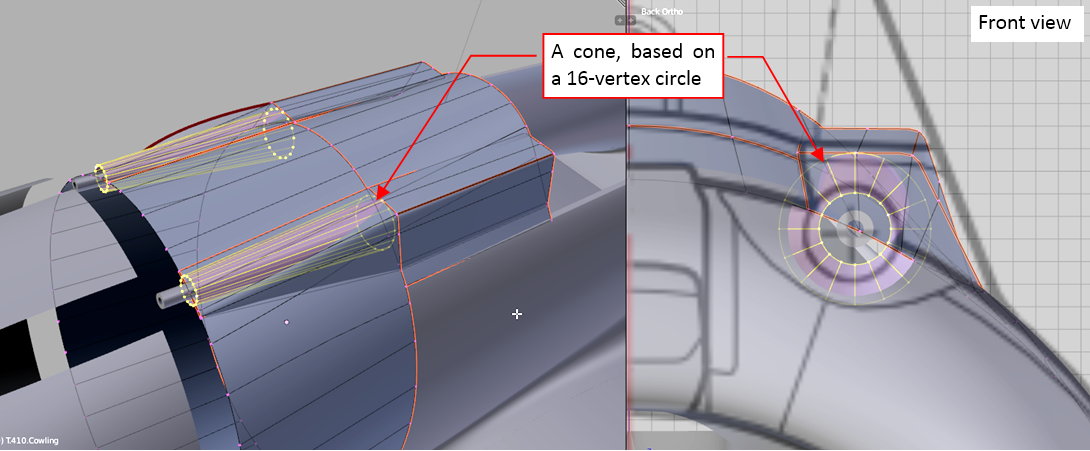
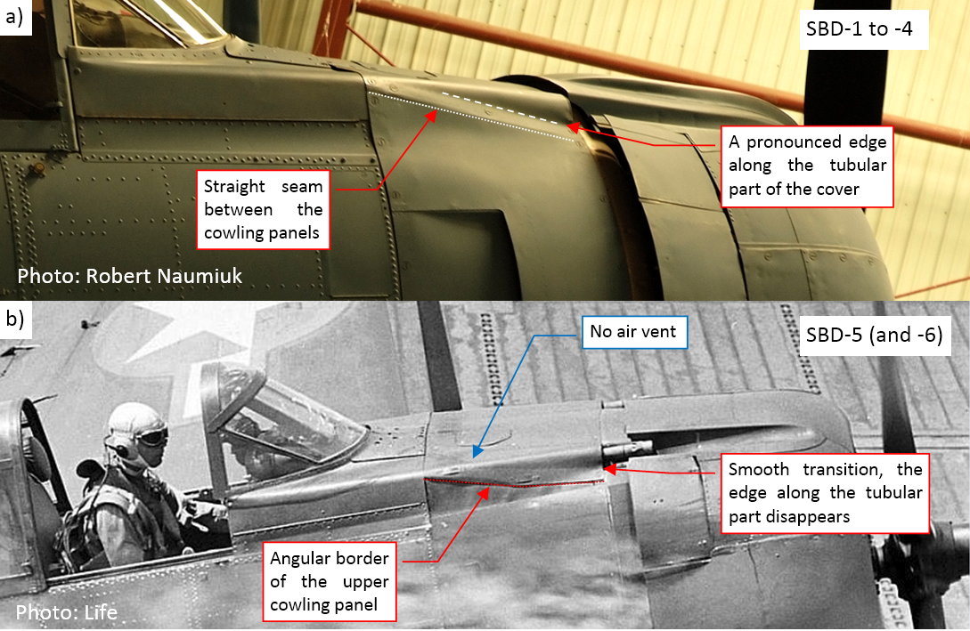
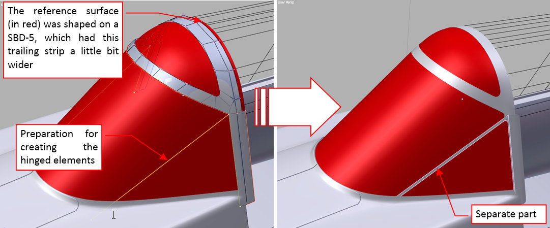
First of them are the covers around the M2 gun barrels. They were hinged around their inner edges, and their cross-section varies from a semi-circle at the NACA cowling to a flat line at the firewall:
I started forming this cover from a conic cylinder, created around the gun barrel:
Then I cut out its bottom part and flattened its end section along the side “bulge”:
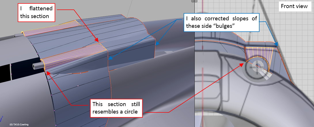
I formed it to resemble the gun barrel covers as they were in the SBD-1…-4s. Studying the photos I identified that this detail looks a little bit different in the SBD-5 and -6:
As the last element of this auxiliary object I will form the windscreen. I need it for determining the ultimate slope of the “bulges” around the breeches of the M2 guns, and for checking the shape of its intersection with the fuselage. (If I did it later, it could reveal some unexpected surprises about the fuselage geometry, resulting in additional work).
I used the reference photos to determine the basic radii of the canopy hood and the windscreen cross sections:
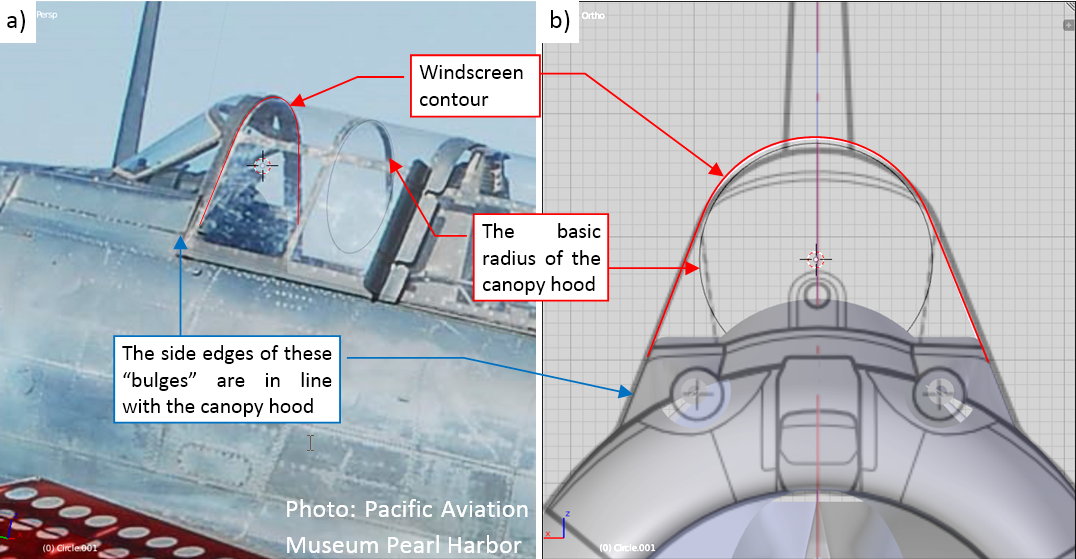
(In this aircraft canopy hood slide under the windscreen, thus the radius of the windscreen cross-section was a little bit larger). As you can see in Figure “b”, abve, the obtained contours differs a little to my reference drawings. (It seems that on these drawings the top of the cockpit canopy is a little bit lower than I have ultimately found it now on the photos).
In the next step I determined the radii of the cylindrical fragment of the windscreen:
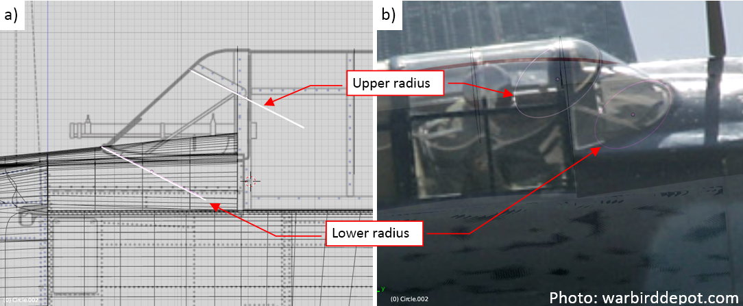
It seems that it was not a regular cylinder — its radius at the top of the windscreen seems to be larger than the radius at the bottom (figure “a”, above).
I created this cylinder as the first part of the windscreen surface (figure “a”, below). I verified its shape using another reference photo (figure “b”, below):
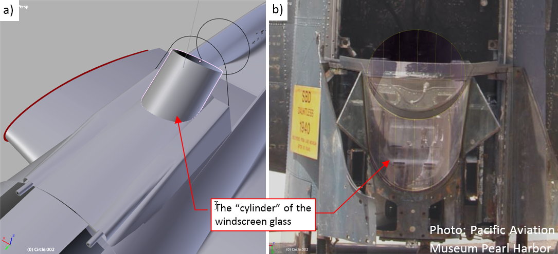
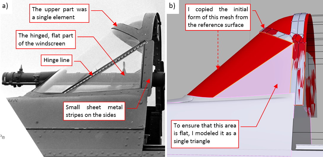
In the next step I removed the rear part of this cylinder and formed the flat, triangular side plates of the windscreen. As you can see in figure “b” above), they were hinged, providing the maintenance access to the M2 guns on the cockpit sides.
Then I extruded two additional rows of faces, forming the upper part of the windscreen (figure “a”, below):
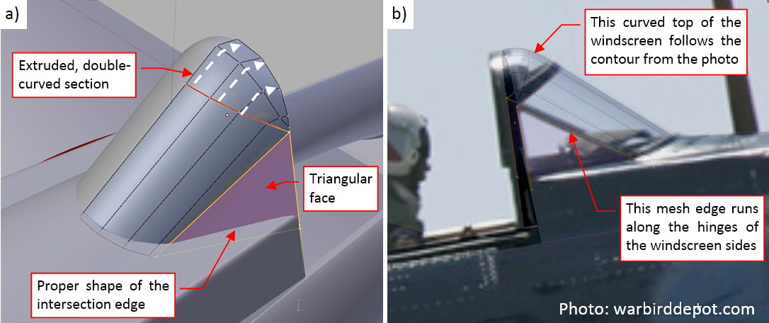
When the shape of the intersection between the windscreen and fuselage matched the reference photos, I also verified its side contour (figure “b”, above).
Figure “a” below shows the complete object that approximates the shape of the SBD engine cowling. I set its color to red, as I do for all the reference objects in this model:
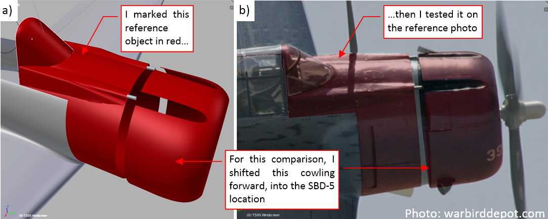
In figure “b” above you can see that it fits pretty well the reference photos. This is a picture of the SBD-5 from Chino Air Museum. The SBD-5 and -6 had their engines and the NACA cowlings shifted forward by about 4”, so did I in this model (see in this post Figure 4-6 for details).
In this source *.blend file you can evaluate yourself the model from this post.
I’ve been following this since it started last year and think the world of this venture that you are on. You point out there are others into this and that’s great. I , for one, appreciate that you are taking the time to post this here for all who are interested here to see. It may at times feel that you are posting to yourself as I don’t see many responses, but I can tell you that I’m watching all this closely.
Joe
Thank you very much! Indeed, I want to popularize this new branch of our hobby. Posting in this thread is just a weekly reporting of the progress. Even when there are no answers, I can see the growing visit counter - and the 5-“star” rating, so it is not bad :).
In this post I describe a break in the modeling that I made this week, because I had to fix my reference photos before the further work. The reason for this fixing was simple: the NACA cowling of my model did fit only the long-lens photos. For the further work I needed more information. This information was available in the high-resolution photos made by the Pacific Aviation Museum Pearl Harbor. However, they are slightly distorted.
In the ‘mathematically ideal perspective’ calculated for the computer cameras all of the straight lines remains straight. Unfortunately, the real-world camera lens can slightly deform (bend) the straight contours. This is so-called ‘barrel’ (or ‘cushion’) distortion of a photo. Unless you are using a panoramic lens, this deformation is hardly noticeable for the naked eye. Unfortunately, these differences become evident when you place a photo behind a 3D model, projected by a computer camera.
In case of reference photos that I used to verify my SBD Dauntless, the differences caused by the barrel distortion are visible around the forward part of the engine cowling:
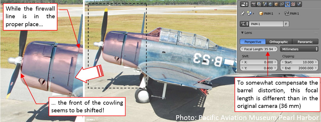
It is really difficult to find the precise shape of this airplane on such a deformed photo. Thus I started searching the Internet for a method that would allow me to revert this deformation. First I encountered some advanced tools, like Hugin software. However, it seems to require series of similar photos to make a really improved picture. None of my single photos met this criteria.
On the Internet I also found some general scientific/engineering papers about the barrel distortion, as well as the tutorials how to fix it (for the architectural visualizations). They advised to use some originally straight contours/lines visible on the photo to estimate the image distortion. Indeed, for the photos as above, I can use the splits between airstrip slabs as such a reference:
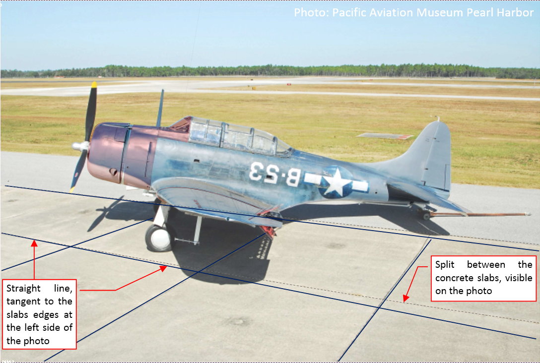
I marked these lines on the photo above using dashed line. To see better their deformation, I draw along them straight lines, in blue. Note that these straight lines are tangent to the dashed lines on the left side of this picture. On the right side of this picture you can see maximum deformation of these split lines. This is the evidence of the barrel distortion.
I tried to reverse barrel deformation of this image using these split lines as indicators. I used a simple Lens Distortion filter from GIMP 2-D graphic program. The idea was that when I apply a deformation that makes these lines straight. Maybe such an operation will reverse the whole barrel distortion in this photo?
Figure below shows the Lens Distortion filter dialog window (GIMP), which I used to find the proper “reverse deformation” for this photo:
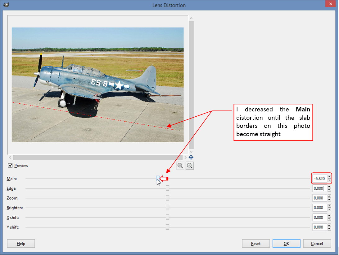
As you can see I used only the first (Main) parameter of this filter. I decreased its value until the split between the airstrip slabs on the preview became straight.
Then I matched the projection of my 3D model to this photo:
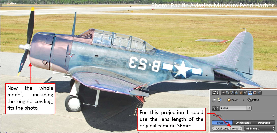
This is really a rough, approximate method, but the obtained results look really promising! Now the whole cowling fits the modified photo!
If it worked well for this picture, I tried it on another one:
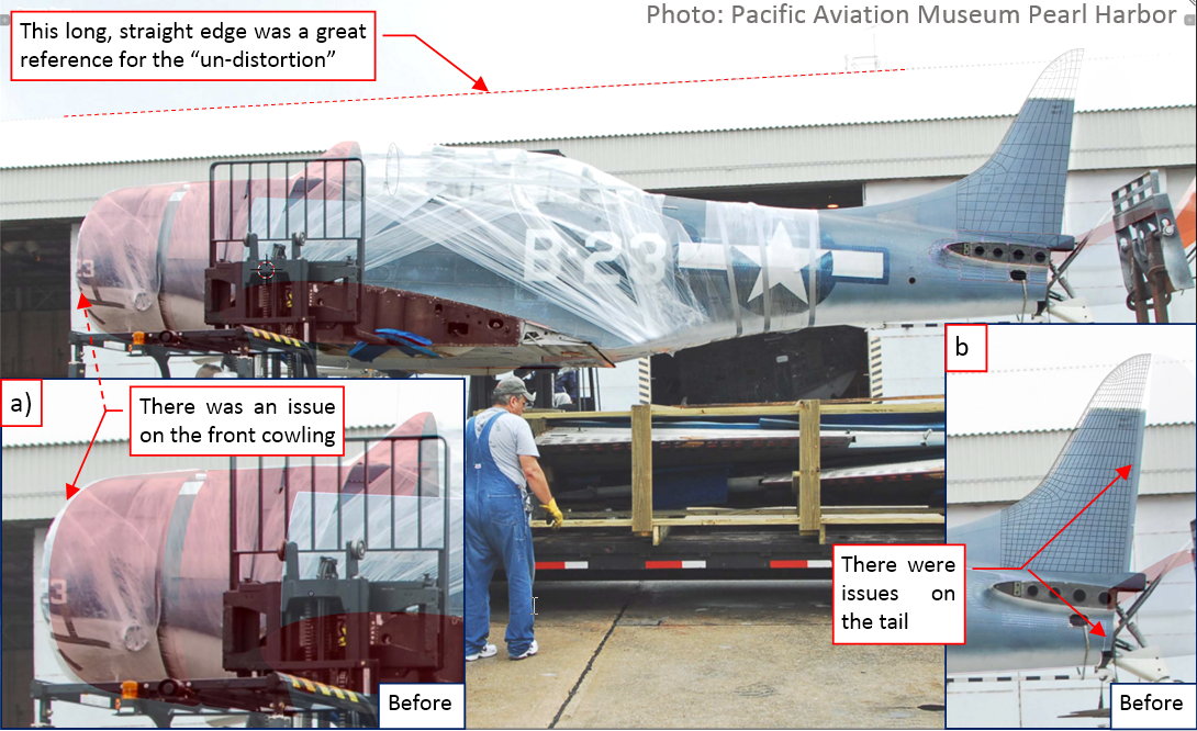
The SBD fuselage spans over the whole length of this photo, thus the barrel distortion is more visible here. You can see it in the fin and the last bulkhead (see figure “a”, above), as well as in the engine cowling (see figure “b”, above). However, the contour of the hangar roof was a great reference for the reverse deformation. What’s more, the GIMP dialog windows preserves the last used parameters. Thus I even did not have to adjust again the Lens Deformation filter! The same value of Main = -6.8 (as set in the filter dialog window - see the third figure in this post) made this hangar roof ideally straight. Both photos come from the same source, and their EXIF data reveal that they were made by the same camera. Thus I think that this deformation value is the “constant” property of this particular camera, which is repeated in each photo it made.
As you can see in figure above, after reverting the deformation, this picture perfectly matches the 3D model over the whole length, from the cowling to the fin.
During careful examination of all the nook and crannies of the fuselage, I encountered the difference at the root of the tailplane. In my model this rib seemed little bit shorter than in the photo (figure “a”, below):
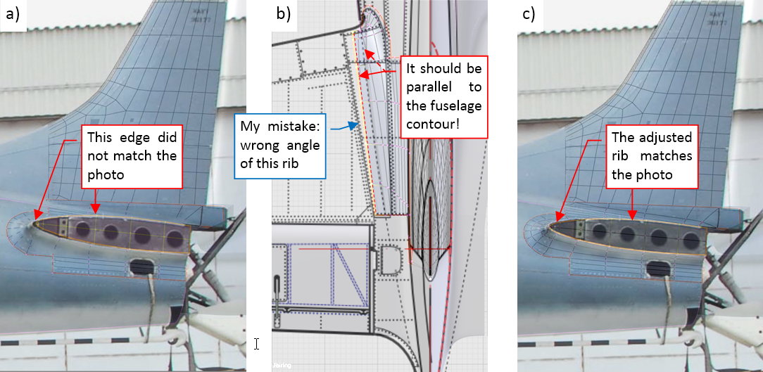
When all other element of this section fits the photo, such a gap means a real difference between my model and the original airplane. After some tweaks I decided that this rib was less deflected from the fuselage centerline (figure “b”, above). (It seems that I made wrong estimation of its angle when I sketched these drawings). In fact, this rib run in parallel to the fuselage surface. Figure “c”, above, shows that such a modified rib fits the reference photo pretty well.
As in the science: the theory is widely accepted, when it allows you to discover something previously unknown. These updated photos allowed me to find another error in my model!
I quickly converted most of the other photos from the same air museum. Unfortunately, I encountered the limits of this simplified method, when I tried it on the photos taken from a ¾ view:
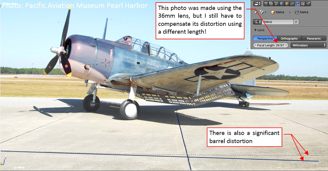
I could not fit the model to the modified version of this photo! I had to revert to the original picture and its matching (using a slightly different lens length co compensate most of the barrel deformation).
It seems that the simple method of applying Lens Distortion deformation works only for the objects set in parallel to the picture plane.
For the consolation, I scanned again the Google image search (I have not done it for over four months). It was a fruitful idea, because I found two new reference photos, made by a long-lens (600 mm) camera. (They were published in this post from General Aviation News blog). The first of these pictures is even more banked aircraft than I have found before:
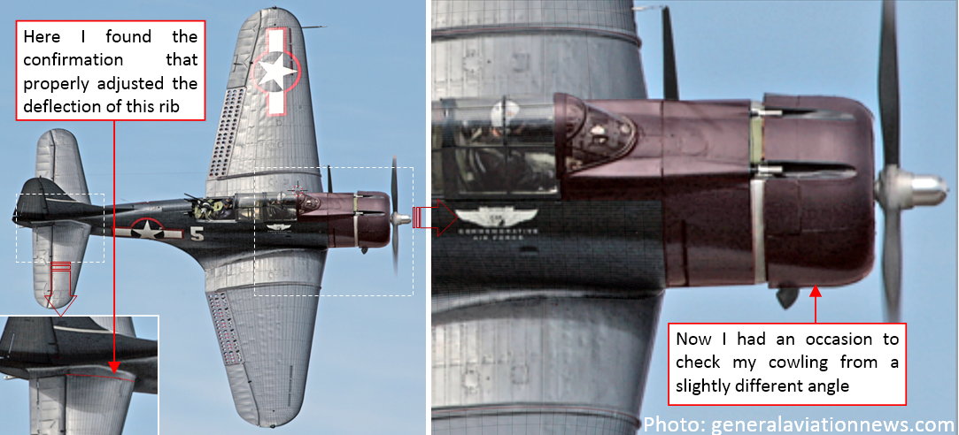
In spite of the same Navy blue camouflage, this is a different SBD-5 from Commemorative Air Force (note its ‘5’ side number). It allows me to verify the important details of the vertical view: the width of the fuselage or the shape of the engine cowling. As you can see, the model fits this photo pretty well. In particular, I found here the confirmation of the new deflection angle of the tailplane root rib.
Another photo is an extremely high resolution (5400 x 3600 px) picture of the same aircraft, taken during landing. It allows me to check better the side view details:
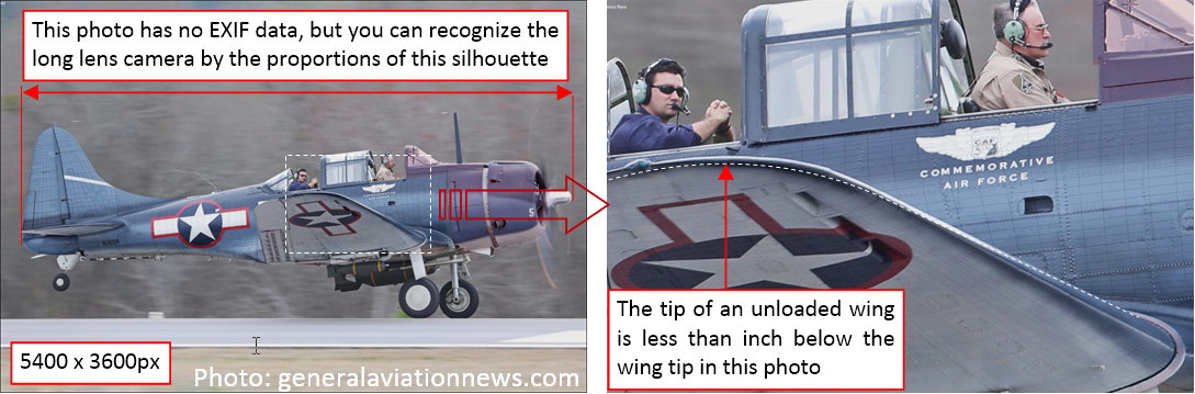
Ultimately, on such a detailed picture I was able to find the dynamic deformation of the wing: it is slightly bent upward, so its tip is no more than an inch above its non-loaded location. The Dauntless wings were as stiff as in the fighters!
In this source *.blend file you can find one of these updated photos.
In the next post I will start to work on the NACA cowling details, using the reference objects formed in the two previous posts.
In this post I will shape panels of the Dauntless NACA cowling. Working on the scale plans a couple months ago I came to the conclusion that the basic shape of this cowling was the same in all the SBD versions (see Figure 4.6 in this post). You can find the differences in their ‘ornaments’, like the sizes and locations of the carburetor air intake, or the number of their cowling flaps. Thus I used the high-resolution, long-lens photo of the SBD-5 (described in the previous week), to determine the ultimate shape of this cowling, and the split lines of its panels (figure “a”, below):
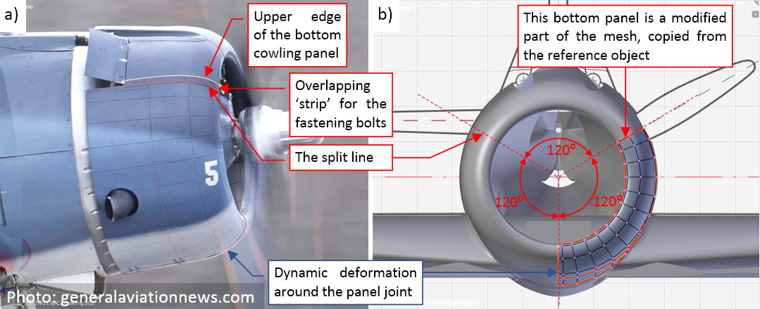
Basically, the SBD Dauntless NACA cowling was split into a single upper panel and two symmetric side panels. I started by copying corresponding part of the reference shape (created in this post) into the single side panel (figure “b”, above). The subdivision surface of such a 120⁰ mesh ‘arc’ is somewhat flat at both ends. Thus I had to tweak a little mesh edges in these areas, fitting them to the reference contour.
In the next step I extruded the ‘strip’ that overlapped the upper panel (figure “a”, below):
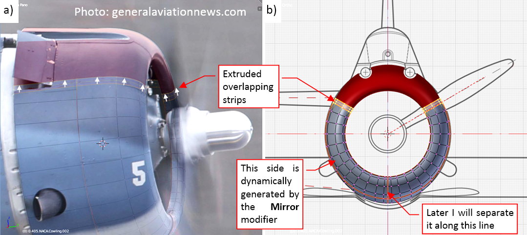
I also marked the bottom edge of this panel as sharp (figure “b”, above). In fact, the right panel overlapped the left panel along this line (they were similar, but not identical).
What’s more, in the SBD-5 and -6 the split line between these panels was shifted left by about one inch. Nevertheless I decided that I will split these two panels later, during the detailing phase. At this moment I just dynamically mirrored the left panel using modifiers. It will be easier to unwrap in the UV space this single element, then copy its unwrapped mesh and form the right panel during the detailing phase.
To keep the topology of this mesh as simple as possible, I decided to cut out the exhaust stacks openings using a Boolean modifier:
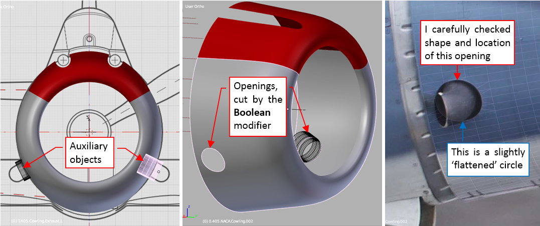
The high-resolution photo was a very useful reference for the ultimate check of the shape of this opening. (Its contour contains two arches connected by short straight lines).
In a similar way I cut out the space for the cowling flaps:
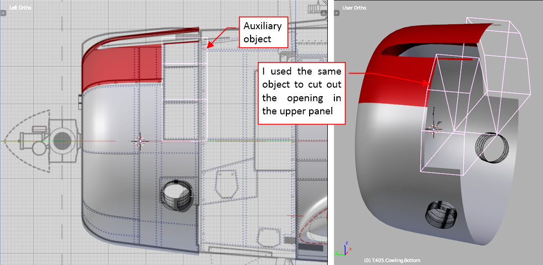
Actually, I am preparing the three-flaps sections, as used in the SBD-1… -4. Note that I used the same auxiliary object to cut the upper cowling panel.
The overlapping ‘strip’ along the upper edges of the side panels was chamfered just on the cowling leading edge (figure “a”, below):
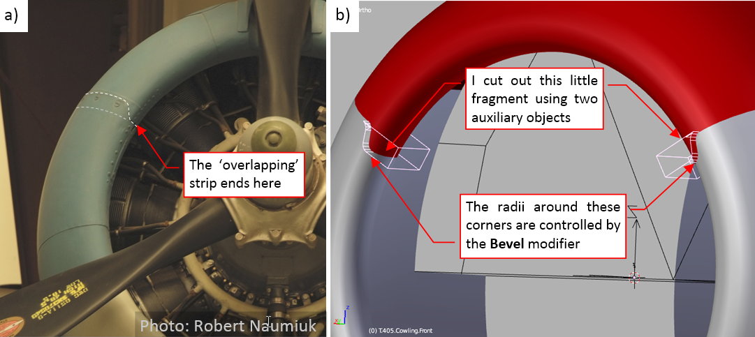
It would be very difficult to shape such an effect ‘in the mesh’ here, because of the two-dimensional curvature of this area. That’s why I created it using two auxiliary objects and another Boolean modifier (as in figure “b”, above). This was the last detail of this panel, for the modeling phase.
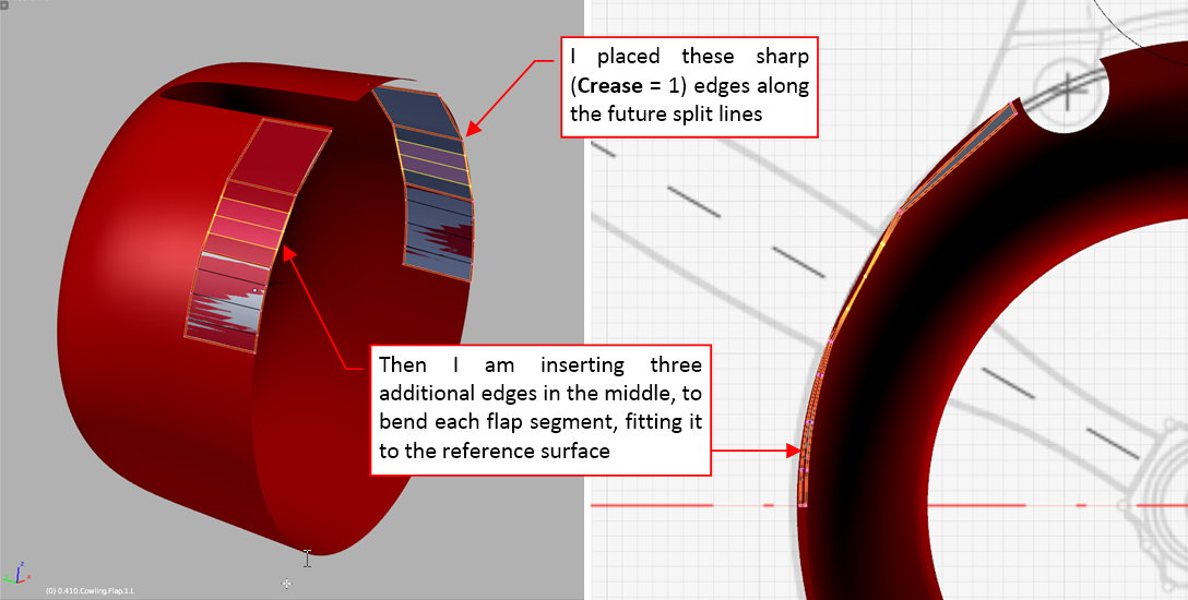
The next element are the cowling flaps. Initially I created them as a three-segment ‘strip’ (one quad face per each flap). I marked all edges of this initial mesh as ‘sharp’ (Crease = 1). Once I determined the size and shape of these basic faces, I added new, internal edges and started to bend this ‘strip’ along the reference shape (red object in the figure below):
When this ‘strip’ was fitted to the reference cowling panel, I added temporary edges connecting their opposite vertices. These auxiliary lines helped me to determine direction of individual rotation axes of these flaps, as well as their origins (figure “a”, below):
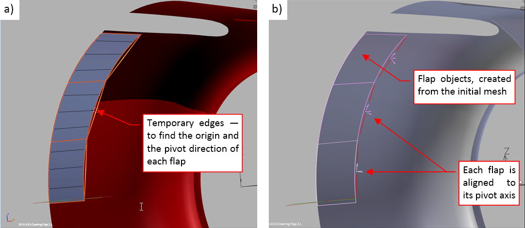
Then I separated appropriate fragments of this mesh into three cowling flaps (figure “b”, above).
Finally I cloned and mirrored the three left cowling flaps into the three right cowling flaps (figure “a”, below):
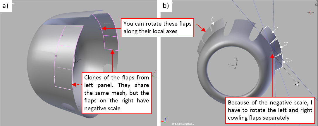
At this moment the right flaps objects have a negative scale, thus for the movement test I have to rotate these left and right flaps separately (along their local Z axes, using the Individual Centers pivot point mode — as in figure “b”, above).
In this source *.blend file you can evaluate yourself the model from this post.
In the next post I will form the gun recesses in the upper cowling panel. It will be a quite difficult detail!
Where did you learn this art?
Well, I am a self-taught. I determined my methods using various available resources (books and tutorials). However, I paved the way for the others, describing everything in a comprehensive guide [*] :).
The gun recesses in the aircraft usually are tricky elements. Their edges depends on the shape of two curved surfaces: the fuselage around the recess and the tubular inner surface. When you make mistake in any of these two shapes — you have to remodel the whole thing.
In the SBD there are two symmetric gun recesses in the upper part of the NACA cowling. Figure below shows the left one:
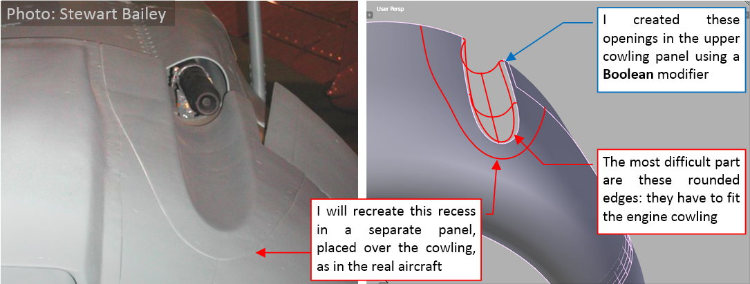
As you can see on the photo, these recesses were formed in a separate metal sheet. It was riveted afterwards to the main body of the NACA cowling. I will repeat such an arrangement in my model, because using a separate object for such a feature simplifies its mesh. (I can make this mesh denser than the NACA cowling around it, and still I do not have to worry about the topological implications). The sheet metal around these recesses seems to be relatively thick, which ultimately makes the fitting of this panel to the NACA cowling surface easier. To make some space for this dedicated panel, I created initial openings for the gun recesses in the upper panel of the NACA cowling. They are generated by a Boolean modifier, and are a little bit larger than the final recesses.
The most difficult part of the gun recess in this aircraft is the fillet around its edge. To obtain a high-quality shape, I decided to start this panel as two separate objects. The first of them is the tubular inner surface (copied from the “cutting” object used in the Boolean modifier). The second object is just a small cylinder, which radius is close to the fillet radius. I will deform it along a 3D curve, which follows the border of the gun recess opening:
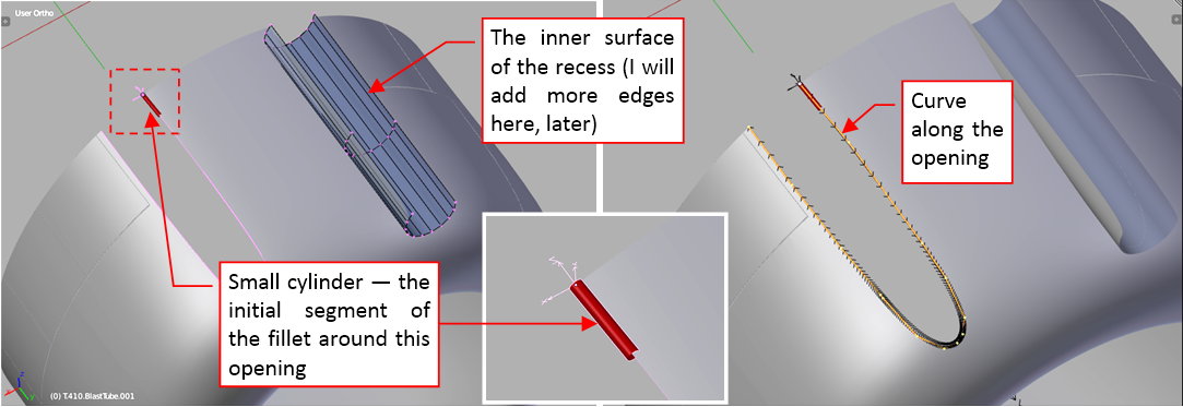
When I started to extrude subsequent segments of the “fillet” cylinder, it automatically follows the assigned curve. (The curve allows me to do it without worrying about preserving the circular cross-section along the whole length of the opening border). Technically, this is the effect of a Curve Deform modifier that I assigned to the cylinder object. This is the first modifier in the stack, and it precedes the smoothing (Subdivision Surface) modifier. Such an arrangement allows me freely slide the circular cylinder sections around the opening border, finding the proper locations for these key vertices:
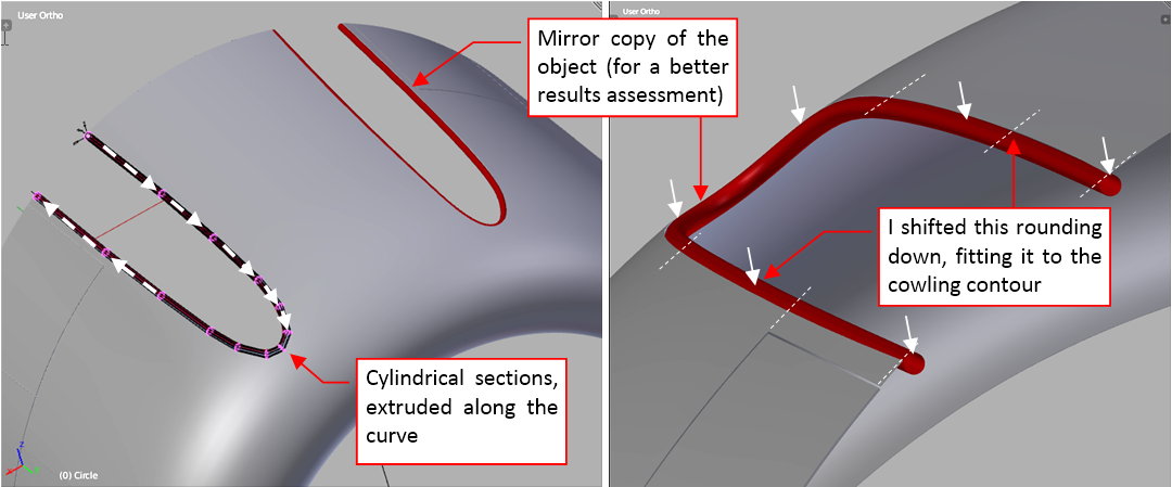
Then I shifted this resulting contour down, and adjusted its “spine” curve so that the “fillet” cylinder barely touches the opening edge.
When the basic cylinder was shaped, I removed (applied) the curve modifier, as well as the unnecessary ¾ of the cylinder surface. The result is a regular fillet, formed around the opening (figure “a”, below):
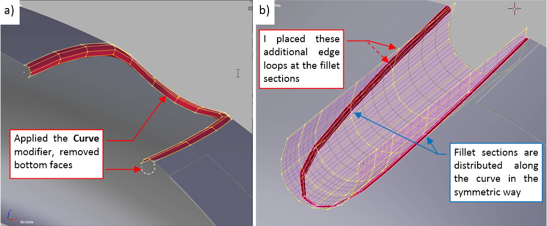
Now I started prepare the inner part of this recess for joining with this fillet. I had to add some additional sections. They are placed at the corresponding sections in the fillet mesh (figure “b”, above).
When all the edges of the inner recess mesh were verified and adjusted to match the filet, I joined these two objects and removed the unnecessary faces (figure “a”, below):
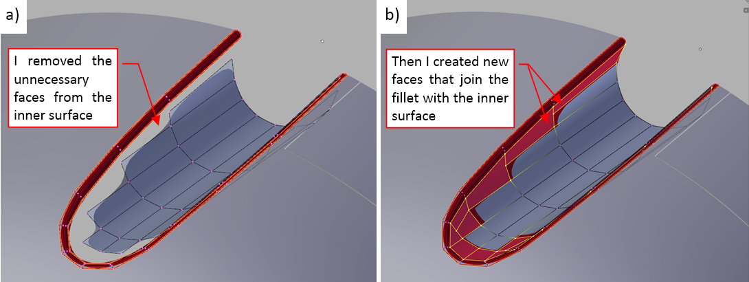
Then I created new faces that join these two meshes (figure “b”, above).
Once the inner part of the recess panel was completed, I started to form its outer part by extruding its outer edge (figure “a”, below):
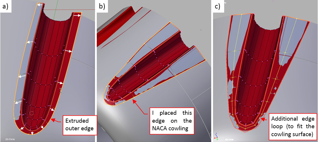
I placed its vertices on the outer edges of this panel (figure “b”, above). Then I added another edge loop in the middle and started to elevate the ‘sunken’ part of this surface above the cowling panel (figure “c”, above).
Figure “a” below shows the outer surface neatly fitted to the cowling. As you can see, it requires not one, but two inner edge loops outside the fillet, to reproduce circular cross section of the NACA cowling around this recess:
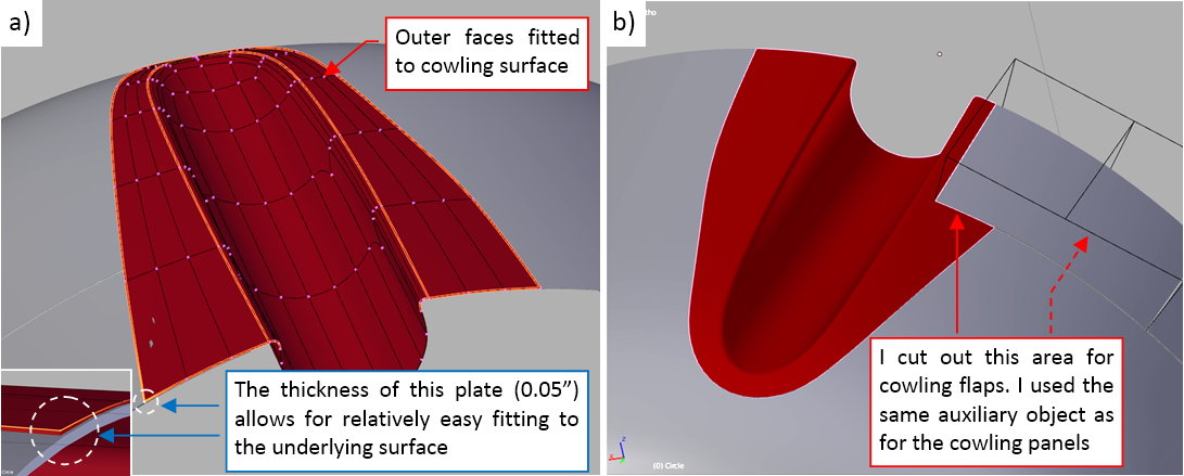
Finally I used the same auxiliary object as for the underlying panel to cut out the space for the topmost cowling flap (figure “b”, above). (It is made using the Boolean modifier).
The gun recess in figure “b”, above, looks good enough. However, when I looked onto another reference photo, and then onto another, I slowly started to discover that these recesses had different cross sections! I assumed that it was an arc, while the more I study the photos, the more I came to a conclusion that it had narrower, ‘U’-shape cross-section!
Such surprises are common, when you are making a precise model. Thus, do not assume that the progress of your work will go as a “waterfall”. It is more similar to a “spiral”: you often come back to the completed parts and adjust some of their details. Just keep the objects ready for such situations: they are normal part of the work.
That’s why I still keep as much features as possible implemented as the modifiers applied to relatively simple meshes. Thanks to such an arrangement, the adjustment of the recess shape does not require a lot of work:
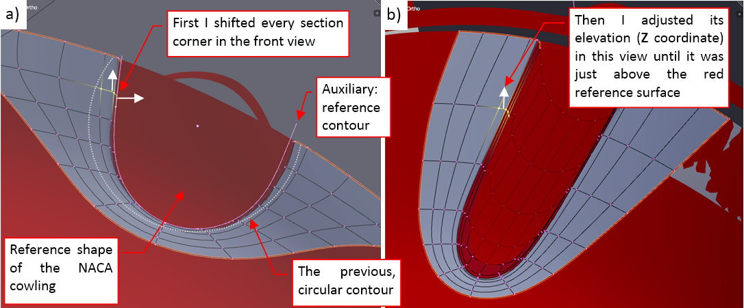
First I created a simple auxiliary object as the reference of the correct cross-section shape (white contour in figure “a”, above). Then I placed the panel being modified over the reference shape of the NACA cowling (in red). Then I started to shift the complete fillet sections and the near lengthwise edges in the front view, placing them on the new contour. When it was done, I made minor adjustments along the recess edge, shifting the fillet sections until they fit the red surface of the NACA cowling
The difference in colors helps me to estimate the remaining deviations from the reference surface. I usually shift the modified section downward, until the resulting gray surface around it ‘sinks’ in the red reference surface. Then I move it minimally upward, so that the resulting surface appears just above the reference object.
Figure below shows the final result: gun recesses in the upper panel of the NACA cowling:
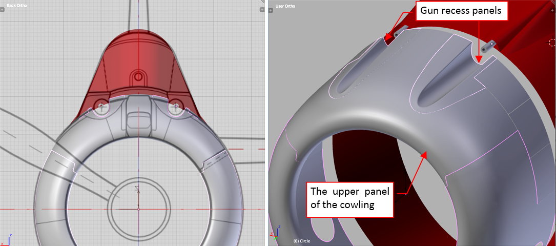
For convenient “handling”, the gun recess panels are attached to their cowling panel by the “parent” relation in the internal hierarchy of this model.
In this source *.blend file you can evaluate yourself the model from this post.
In the next post I will form another element of the upper cowling panel: the carburetor scoop.
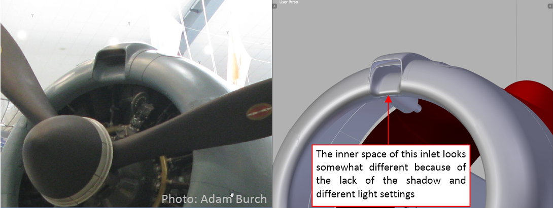
This week I have worked on the carburetor air scoop. This scoop passed significant evolution in the subsequent Dauntless versions. In the SBD-1 there was a rather large air duct placed on the top of the NACA cowling (see figure “a”, below):
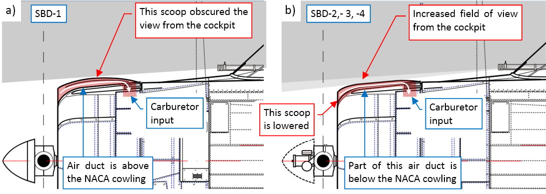
However, it was quickly discovered that it obscures one of the most important spots in the pilot’s field of view: straight ahead and slightly below the flight path. That’s why it was somewhat corrected in the next version (SBD-2). In this aircraft the designers lowered the scoop, increasing the field of view from the cockpit (see figure “b”, above). Such a solution persisted in the SBD-3 and -4. In the SBD-5 they completely redesigned it, placing the carburetor scoops inside the NACA cowling (more about this — see in this post the paragraphs around Figure 11-6).
Close examination of the various reference photos led me to the conclusion that in the SBD-1 the air duct ran between the inner surfaces of the scoop and the top of the NACA cowling (figure “a”, below):
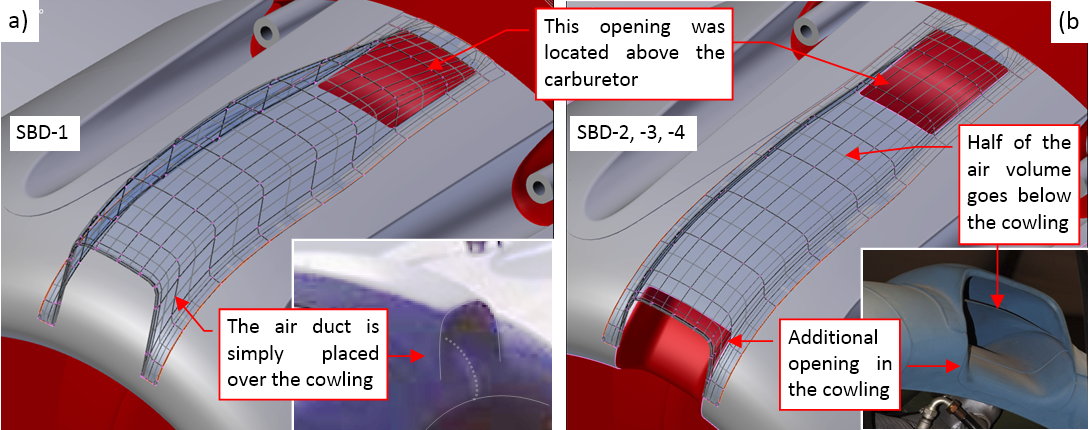
There was a rectangular opening in the rear part of the cowling, located just above the Bendix-Stromberg carburetor of the R-1820 engine. (There was a short, vertical duct inside the NACA cowling from this opening to the carburetor intake. I will model it later, together with the engine).
The later scoop version (from the SBD-2, through SBD-3, up to SBD-4) was a typical “quick and dirty” solution for the identified problem. The designers could not split the upper panel to place the lowered air duct there, because it would hinder the stiffness of the whole NACA cowling. Instead, they cut out another rectangular opening in its leading edge (figure “b”, above). In this way a half of the incoming air went to the engine as before, over the NACA cowling. However, the bottom part of the air stream was directed below the cowling surface. Both streams were joining inside the rear opening, before they went into the carburetor.
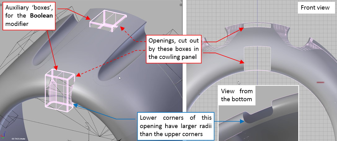
I created both openings using Boolean modifiers:
Then I started by forming the lower part of the air intake. I started with a single strip fitted to the side edges of the frontal opening (figure “a”, below):
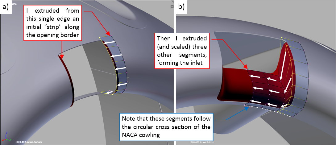
Then I extruded this edge and flatten the subsequent segments, forming the characteristic shape of the inner inlet, as in the reference photos (figure 'b", above).
When this first part of the bottom air duct was ready, I extruded its subsequent segments, forming the rear part (figure “a”, below):
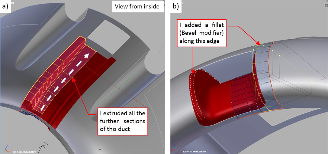
Finally I reduced the roundings along the duct side edges by adding there a multi-segment Bevel modifier. It not only diminished their size, but also made its cross section more circular (figure “b”, above).
When the bottom part of the scoop was ready, I started the upper part. It begins in the same way: from a single strip, fitted to the cowling surface (figure “a”, below):
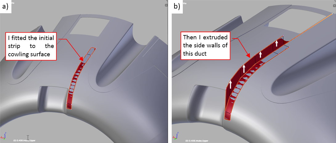
Then I extruded the vertical faces (figure “b”, above).
In the next step I extruded their upper edge into the horizontal surface (figure “a”, below):
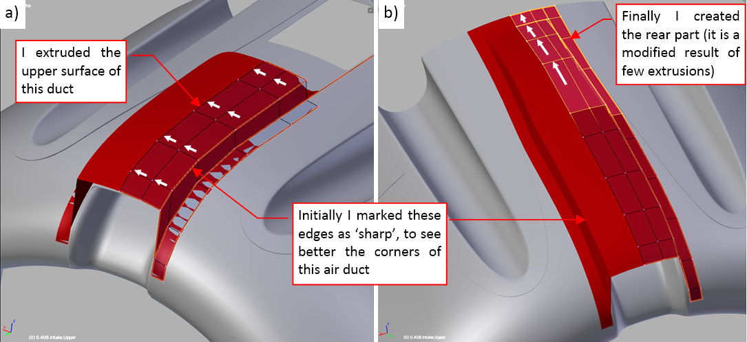
Finally I extruded the subsequent segments of the rear part of this mesh (figure “b”, above).
Initially I kept the lengthwise edges of this object sharp, because I intended to create their fillets using the Bevel modifiers. However, a careful study of the reference photos revealed that the radii of the upper and bottom edge vary along the length of the scoop. Thus I created them by adding two additional lengthwise edgeloops to this mesh:
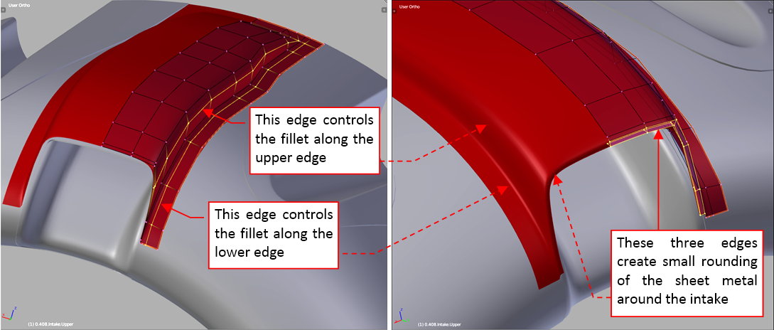
Figure below shows the real scoop (on the left) and the final version of the same scoop my model (on the right):
Although I did not managed to set up the picture on the right precisely as in the left photo, the carburetor scoop looks quite similar on both images. I can leave it “as it is” and start the work on the next cowling element. I can always fix its shape during the next stages of this project.
In this source *.blend file you can evaluate yourself the model from this post.
In this post I will finish the engine cowling of the Dauntless (of course, for this stage of the project). In the previous posts I formed its outer panels. In the case of the air-cooled radial engines like the one used in the SBD, there is always another, inner panel: the central part of the cowling. It is located behind the cylinders and exhaust stacks. In the classic arrangement of the NACA cowling it is nearly invisible. In the SBD-1…-4 you could see only its outer rim. That’s why I had to use all available pictures of the Dauntless engine maintenance or the wrecks, to learn about its general shape:
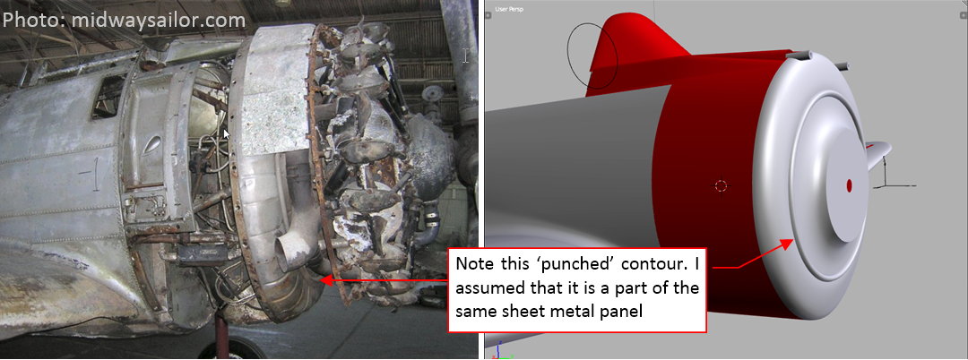
This panel had two variants. The first one (let’s call it “flat”) is visible on the photo above. It was used in the SBD-1…-4. In the SBD-5 and -6 the engine was shifted forward by 4”, so the central panel became a little bit longer (“deeper”).
Frankly speaking, I still need more photos and drawings to better determine the shape of this part, especially the details of its earlier, “flat” version! Let me know if you have one — I am especially interested in the upper area, around the carburetor, in the SBD-1…-4. (The few photos that I have reveal that behind the upper cylinders of the R-1820 engine there was a vertical air duct from the air scoop to the carburetor. I still need to determine its shape, as well as the shape of the inner cowling around it).
That’s why I decided to determine the exact shape of this hidden panel later, when I fit the engine and its mounts. (I count on the indirect information coming from the geometry of the engine mount and the exhaust stack shape). At this moment I am leaving this area “as it is”, because too much of its geometry is based on my assumptions.
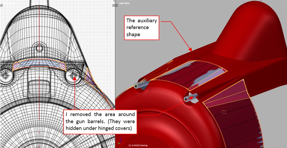
However, I can precisely shape the recesses around the gun barrels, because they are better visible on the photos. I have to make these details easily adaptable when I have to alter the shape of this panel. (I expect that in the future I will tweak the area around the carburetor multiple times, before it “stabilizes” in the most probable state).
The cross-section of these gun recesses have the same shape as their troughs in the NACA cowling. Thus I started by copying the control polygon of this “U”-like cross-section shape (five control vertices) and extruding it into an auxiliary “trough” (see figure “a”, below):
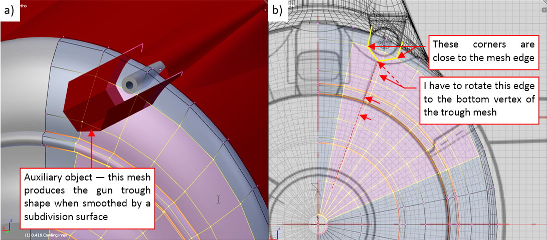
I examined the interesection edge of this auxiliary object with the central panel. The goal was to place its vertices as close as possible to the existing mesh edges. I could easily check it in the front view, because the “trough” in this projection is reduced to a single contour (figure “b”, above). While the both of its side vertices are very close to one of the elliptical edge loops, the middle vertex was too far from the nearest radial edge loop. I had to adjust the mesh of the central panel by rotating a little all of its upper radial edges.
After these preparations, I generated in the panel mesh the intersection edge with the auxiliary “trough” (I used my Interesct add-on for this purpose):
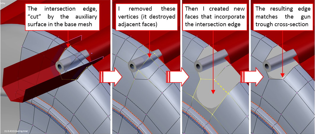
I removed the three vertices that were inside the contour of this intersection. It also deleted all the mesh faces around these points. Then I created new faces in this place, merging the intersection contour with the rest of the mesh of this panel (as in the figure above).
Figure below shows how I created the inner surface of this gun trough:
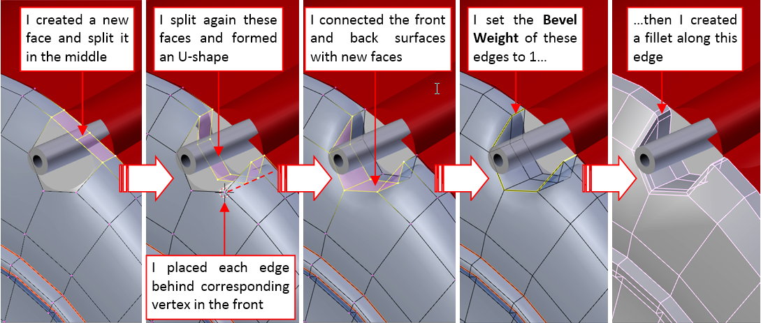
I started by creating a new face that “bridged” the opposite edges of the opening. Then I split it twice, obtaining three inner edges. I placed these edges directly behind the corresponding vertices of the opening contour. Then I closed this opening, creating the four remaining faces. (Now I can see that I could do the same in a simpler way, by extruding the bottom part of the opening contour. Never mind, both methods lead to the same result). At this moment the edges of this recess are too smooth. To reduce the radius of this rounding, and make it similar to a regular fillet, I assigned these edges the full Bevel Weight (=1.0). Then I added to this object a multi-segment Bevel modifier (before the smoothing Subdivision Surface modifier). The last picture from figure above shows the faces generated by this Bevel, before they were smoothed.
Finally I compared the shape of the resulting gun trough to the corresponding troughs in the upper cowling panel:
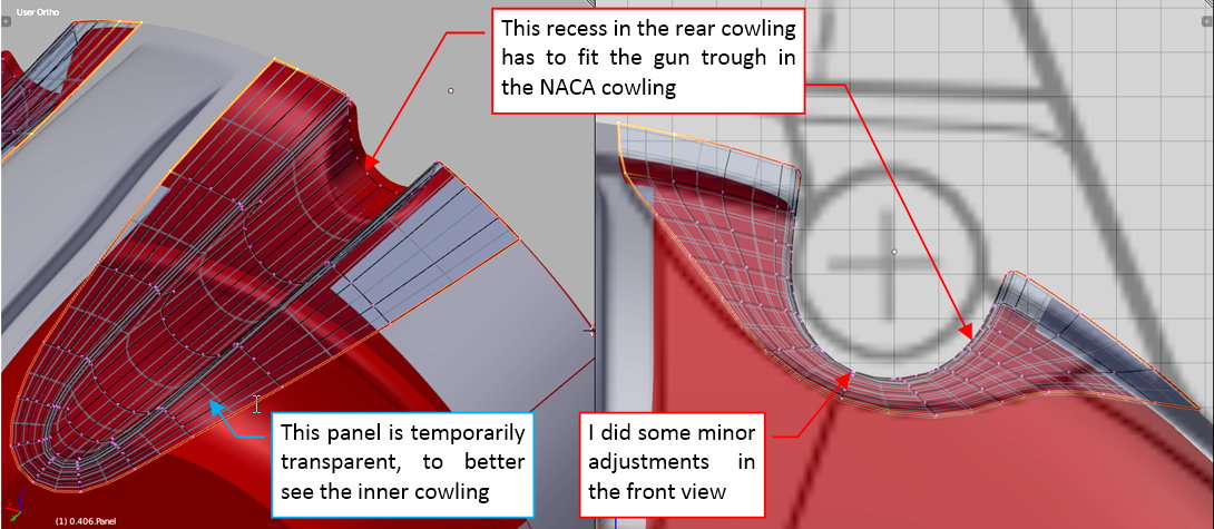
(I made it transparent, to better see the eventual differences in their shapes). Indeed, there were some deviations. I quickly fixed them, adjusting in the front view the whole edges of this recess. (In this view these edges are reduced to a single point).
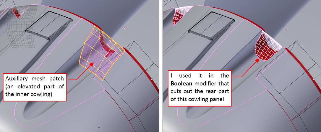
Now I have to trim ends of the troughs in the NACA cowling, creating the space for the central cowling panel. I could do it by modifying their mesh. However, because the shape of this panel may be altered in the future, I decided to use another Boolean modifier for this purpose. I just created an appropriate auxiliary object, and applied it to the gun trough panel:
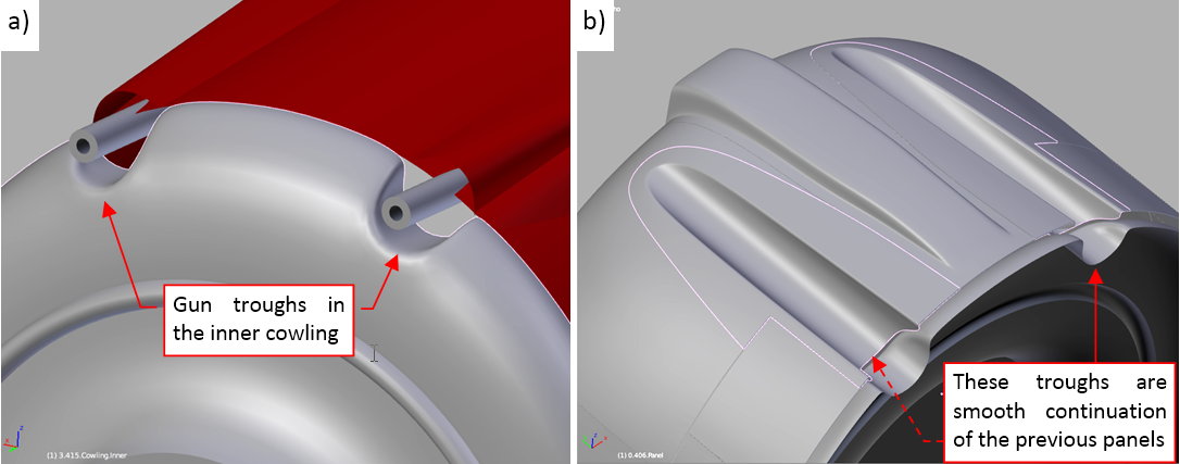
This was the last element of the NACA cowling. Figure “a”, below, shows the recesses in the central panel that I formed in this post, while figure “b” shows details of the whole assembly:
As you have probably noticed in the course of the few previous posts, I had often to move the location of the NACA cowling, switching between the SBD-5 and the SBD-3 versions. To avoid such endless movements in the future, I decided to split the Bledner file of this project into several separate scenes for each Dauntless version that I need. For the beginning I created two additional scenes, for the SBD-1 and SBD-5. They are named after the Dauntless version they contain, thus I renamed the current scene to “SBD-3”.
Figure below shows the SBD-5 scene (and the scene selection menu):
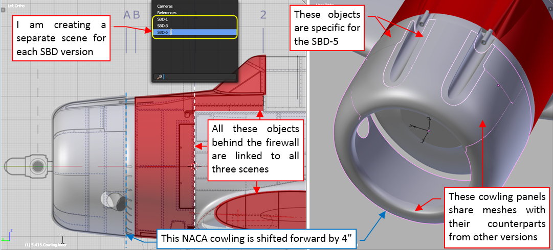
When I created the scene for this Dauntless variant, I chose the option that created it as a copy of the original scene. Initially both scenes share the same objects (the same fuselage object or the wing objects are “linked” to SBD-3 and SBD-5 scenes). In the effect, I can edit these shared objects in any of these scenes. Every change I apply to their meshes, modifier stacks, or general positions/scales/rotations is visible everywhere.
Because the NACA cowling in the SBD-5 was shifted forward by 4”, I had to make in its scene local copies of the panel objects. However, they still share with the SBD-3 their meshes. In the effect, they became “clones” of their counterparts from the SBD-3 scene. Clones share the common meshes, thus they have the same basic shape, but they can have different general transformation (location/rotation/scale). Thanks to this, in the SBD-5 scene the bottom panels of the NACA cowling have the same shape as in the SBD-3, but their location is different. What’s more, the clones can have different modifier stacks. Thus in this SBD-5 model I was able to remove the carburetor scoop openings from the upper NACA panel, and modify the cutouts for the different cowling flaps (see figure above) because they were generated dynamically, by a Boolean modifier.
Ultimately — there are a few objects specific for the SBD-5, which exist only in this scene: the central cowling panel and the panels around the gun troughs. I copied their meshes from the SBD-3 and then modified them according the SBD-5 reference drawings. In the SBD-5 the central cowling panel, placed behind the engine cylinders, was longer by 3.5” than in the previous versions. I had to scale and reshape this mesh. Fortunately, its gun recesses (formed at beginning of this post) are easily adjustable, thanks to their simple topology.
In similar way I created a separate scene for the SBD-1:
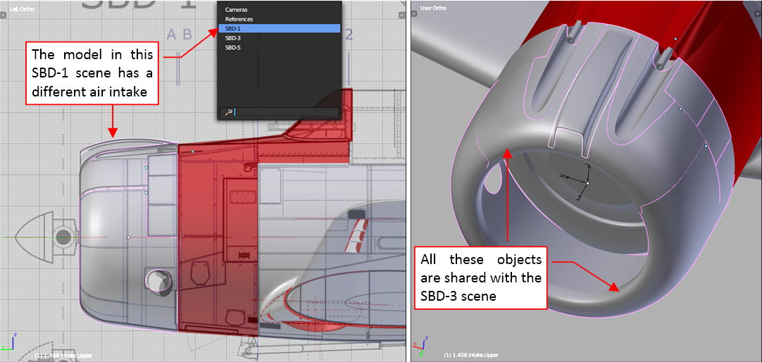
At this moment the only difference between the SBD-1 and SBD-3 is the carburetor scoop on the top of the NACA cowling. However, there will be another minor differences in the next row of cowling panels.
In the future I will also create the SBD-2 scene (combining the NACA cowling from the SBD-3 and further cowling panels from the SBD-1), and the SBD-4 scene (basically – it is the SBD-3 with the SBD-5 Hamilton Standard Hydromatic propeller). As you can see, the SBD-2 and SBD-4 will be just combinations of various parts from the “key” versions (SBD-1, SBD-3, SBD-5), thus I will create them at the end of this build.
In this source *.blend file you can evaluate yourself these SBD-1, SBD-3 and SBD-5 scenes and their initial contents. In the next posts I will continue my work on the SBD-3, then update the SBD-1 and SBD-5.
This relatively short post contains a digression about the aircraft shape. It was sparked by a suggestion that I received. Some time ago Alan from SOARING Simulator.com pointed me that the SBD NACA cowling was not as smooth as in my model (thanks, Alan!). He suggested that its contour was created from a combination of two or three arcs and a straight segment:
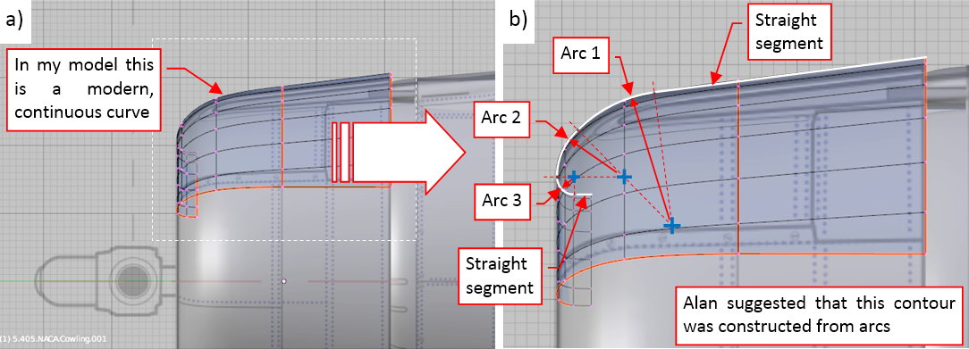
I thought about it and decided that this is a highly probable hypothesis. For most of the 20th century aircraft engineers did not have CAD systems. During that “BC” (“Before Computers”  ) era the typical problem in the ship, aircraft, or car industry was: “how to precisely recreate in the workshops the shapes sketched — usually in scale — on the designers’ drawing boards”. The most important shape — the wing airfoil — was recreated using a “cloud” of data points. However, it was a time-consuming (i.e. costly) method. That’s why for the less important areas, as the fuselage, designers used simpler solutions. The most obvious method to define a specific contour was a curve composed from two or three arc segments. It is relatively easy to recreate such a contour, because you need only to know the radii and the center point coordinates of the subsequent arcs. For example, there are many cases of such curves in the P-36 and P-40. There was also another drawing method for obtaining more “fancy” shapes (like the rudder contours) which was based on a general conic curves. To overcome this problem in a more advanced way the design team of the P-51 “Mustang” described all key contours of this aircraft using polynomial (2D) functions. Still the resulting points of the “Mustang” curves had to be calculated by hand!
The modern, computer-generated curves and surfaces (Bezier, NURBS, subdivision) have continuous curvature (as in figure “a”, above). Thus it requires some effort to recreate in a computer model such a contour like the one sketched in figure “b”, above), where the curvature continuity is broken between each segment. (BTW: the air flow “likes” the shapes that have continuous curvature. That’s why designers always tried to preserve it in the airfoil contours).
All in all, I turned to the reference photos, trying to identify a kind of the contour like the one depicted in figure “b”, above). Ultimately I discovered a more severe break than the lack of the continuous curvature: a minor difference in the tangent directions along the panel seam (i.e. the contour of this NACA cowling does not preserve even the tangent continuity!):
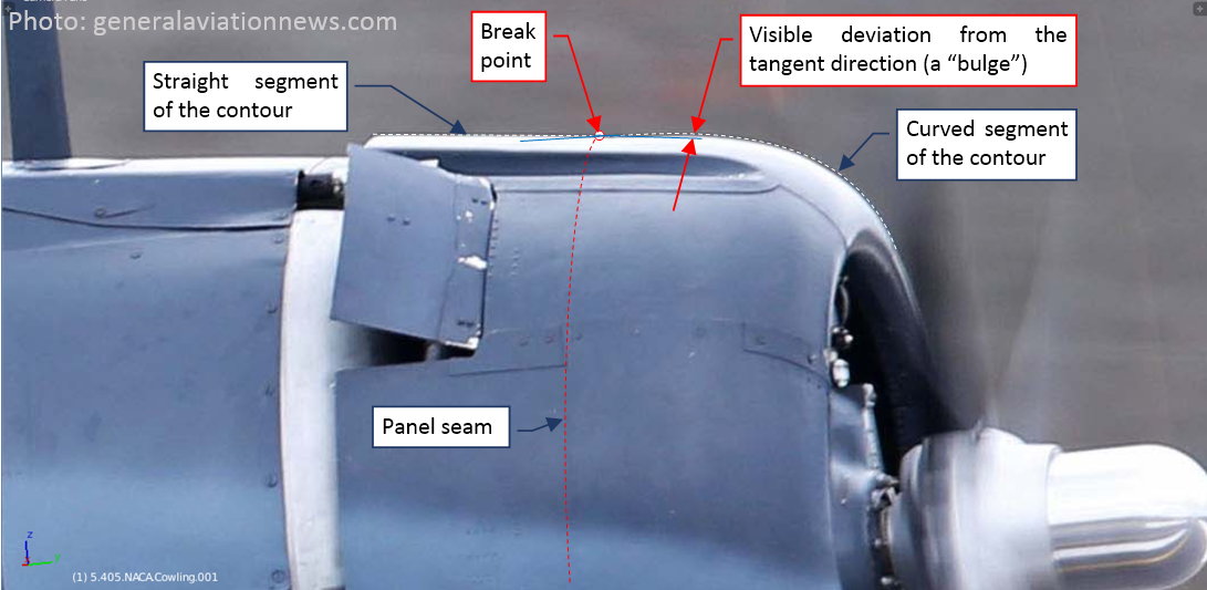
I marked the tangent directions along the panel seam in blue. This is a modern, high-resolution picture of a restored SBD-5. To exclude the possibility that this is an accidental inaccuracy made during restoration, I started to search for this break in all other photos. Surprisingly, I think that I was able to identify this “bulge” in the others SBD-5s. In the previous versions (SBD-1 to -4) it was hidden under the carburetor air scoop. But even there I think that I can trace it in the lines of the nearby panel seams (the gun troughs panels, side edges of the air scoop). Such a small deviations are usually a “side effects” of the technology applied to the particular element. Finally I used the reference photo to recreate this “bulge” in the side view:
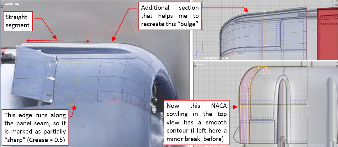
What’s interesting: previously the contour of this NACA cowling had a small convex break in the top view. (When I shaped it for the first time, without the additional section, I was not able to eliminate such a break in the tangent directions. It had to occur somewhere along this panel seam. I had only the choice where to place it, and I decided to leave it on the vertical contour). Now this contour is smooth, and there is a concave break in the side view.
I suppose that initially the forward ring of this NACA cowling was formed as a perfect solid of revolution. Then it was slightly deformed while fitting to the rear, “flat” part of the cowling. The cross section along the seam between these parts is not a perfect circle: it is somewhat higher than wider. Thus the rear edge of the forward cowling sheet had to follow this shape. It altered the tangent dimensions along this panel seam. In the top view it improved the fitting between these two panels of the NACA cowling. In the side view it only decreased the initial difference in the tangent directions.
Well, I hope that this post gives you a better insight, how we can deliberate on each small detail of the recreated airplane. In the overall picture of this aircraft the differences between the shapes before and after modification described above are hardly noticeable. However, I am a hobbyist, and sometimes we are the only ones who have the time to care about such minor things.
In this source *.blend file you can find this modified NACA cowling. (The change in its shape required some adjustments in the other panels).
In this post I will create the next section of the engine cowling. I copied its forward edge from the rear edge of the inner cowling panel. Then I extruded it toward the firewall:
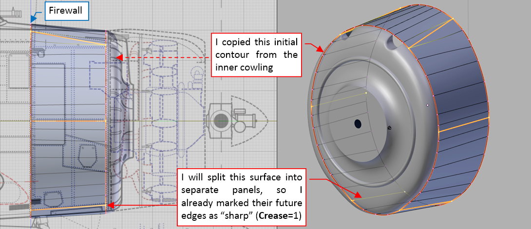
I am going to split this object into individual panels, thus I already marked their future edges as “sharp” (as you can see in the figure above). It allowed me to preserve continuity of the tangent directions around these future panel borders from the very beginning.
In the next step I created the space necessary for the covers of the gun barrels:
Then I split this object into separate cowling panels:
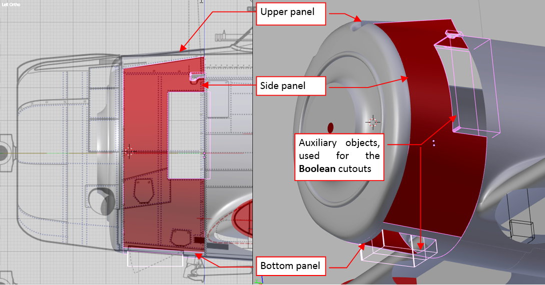
I also used auxiliary “boxes” and the Boolean modifiers to cut out various openings in the side and bottom panel.
To keep the mesh topologies as simple as possible, I decided to model the inner part of the air outlet in the side cowling as a separate object:
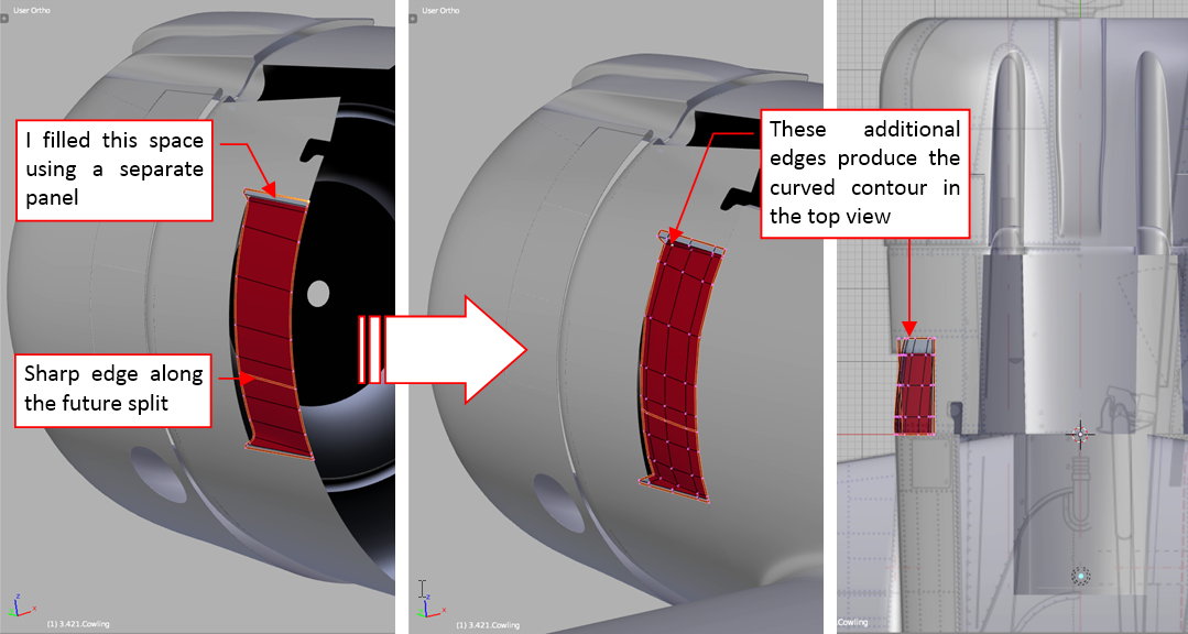
(In the real SBD-3 it was also a separate piece of sheet metal). Its vertical contour was rounded to fit the fuselage behind the firewall (as you can see in Figure 48‑4), thus to shape it in this way I added three additional edge loops in the middle of this mesh.
The initial version of the gun cover was copied from the reference object, then I adjusted its shape fitting it to the adjacent panels (at least to their contours — see figure below):
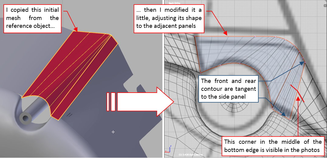
Note that it is possible to have a corner in the middle of the border of a 3D surface that was carefully fit at its front and the rear contour (see the figure above)! In this case this is an intended effect, recreating the effect visible on the reference photos.
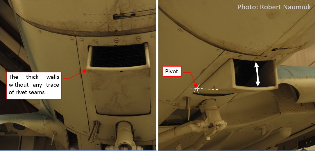
The last element of this cowling is the adjustable scoop (see the figure below), directing the air into the oil radiator (hidden inside engine compartment). It seems to have thick walls, but I suppose that they were empty inside (however, I am not sure — I cannot see any seams there):
I started forming this element by fitting its bottom surface into the fuselage contour:
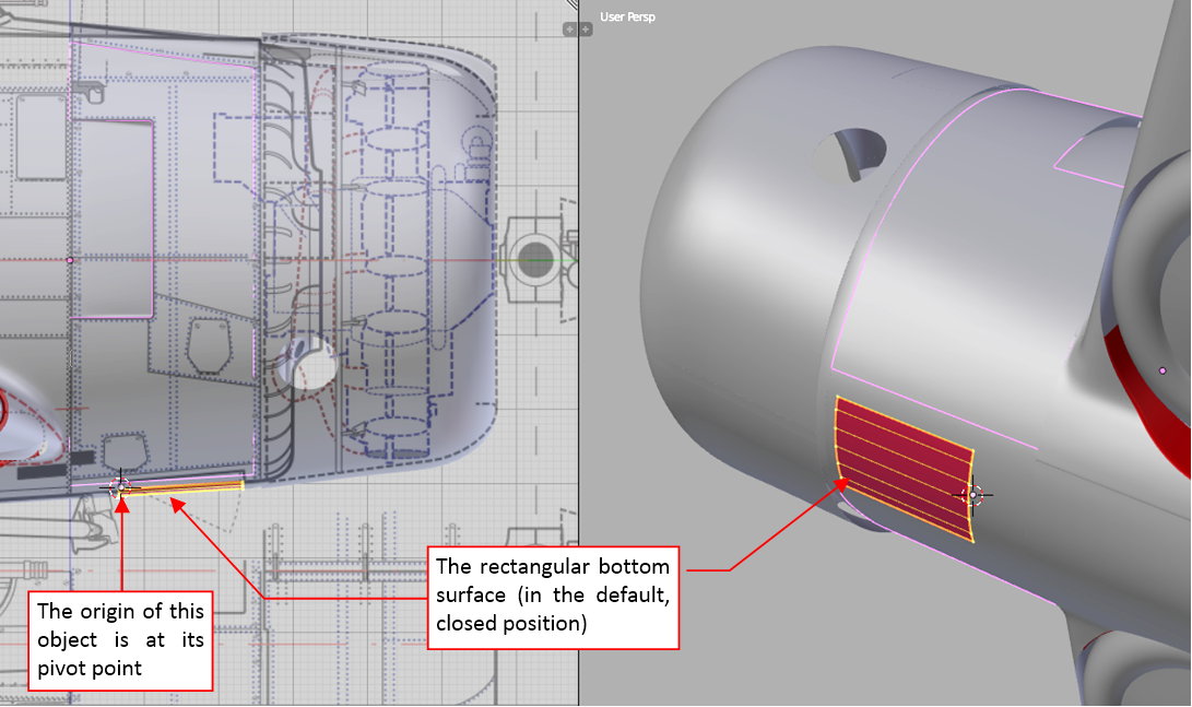
Then I formed the side walls of this object. As the reference I used an auxiliary circle, centered at the scoop pivot point (as in figure “a”, below):
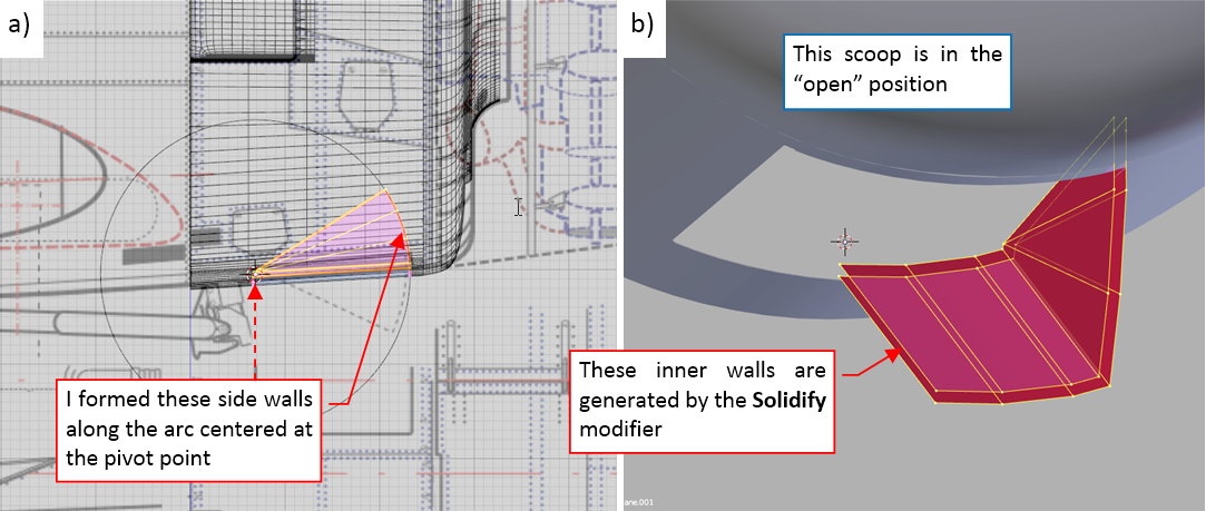
Then I created the thick walls of this scoop using a Solidify modifier (see figure “b”, above)
Initially I was going to round the edges of this object using a multi-segment Bevel modifier, placed after the Solid modifier. However it occurred that the Solid modifier created in some corners of this mesh dynamic faces that cause problems in the result generated by the Bevel modifier. Thus I had to “fix” the results of the Solid modifier before using the Bevel tool. You can see the rounded, thick edges of this scoop in figure “a”, below, while figure “b” demonstrates the complete cowling panels:
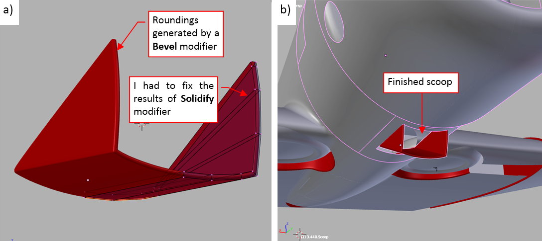
Figure below shows the complete engine cowling, compared to an original aircraft:
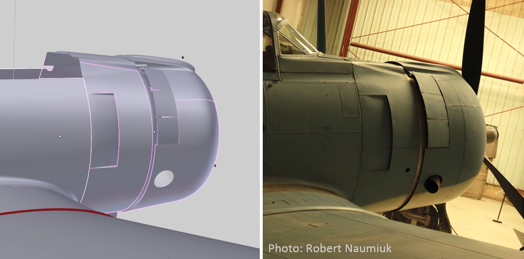
Note that the model in the picture above uses different lighting than in the photo. It results in different shadows and reflections from the curved surfaces of the fuselage.
In this source *.blend file you can evaluate yourself the model from this post.
In the next post I will create the last panel of this fuselage: the hinged doors in the front of the windscreen.
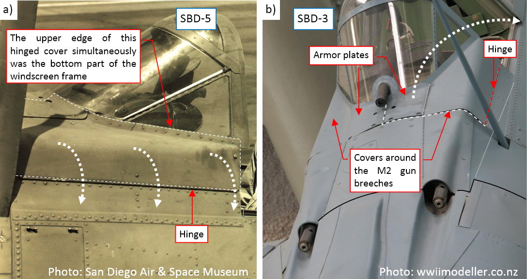
In this post I will form the fuselage panels in the front of the windscreen. In the SBD there were two hinged cowlings, split in the middle. They allowed for quick and easy access to the M2 gun breeches and the internal cabling behind the instrument panels:
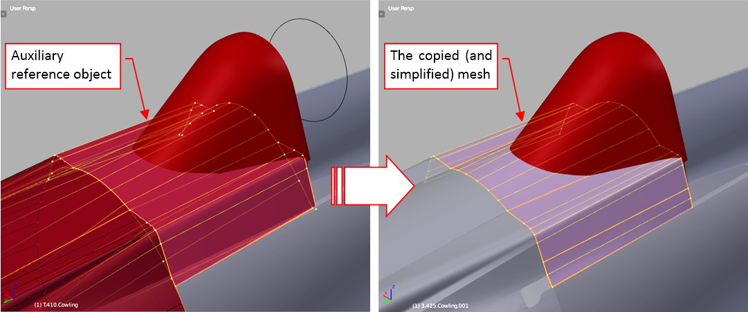
The parts of the fuselage around the cockpit are always tricky to model. It especially applies to the panel around the windscreen. When you obtain the intersection edge of these two objects, it can reveal every error in the windscreen or the fuselage shape. To be better prepared for this task, I created an auxiliary, simplified model of this fuselage section (see this post and the next one). Now I copied a part of it as the initial mesh of this panel:
In the next step I used my Intersection add-on to obtain the intersection edge between this mesh and the windscreen object (see figure “a”, below):
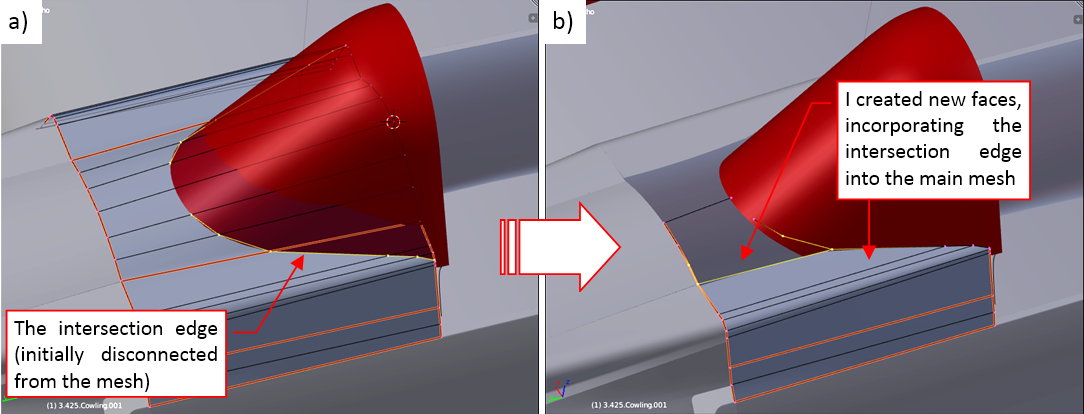
Initially this edge is not connected to any of the mesh faces. To fit this panel to the windscreen I removed some of the original faces and created in their place the new ones. They incorporated the intersection edge into this mesh (see figure “b”, above).
The resulting curve that I obtained in this way required just a few minor adjustments (see figure “a”, below):
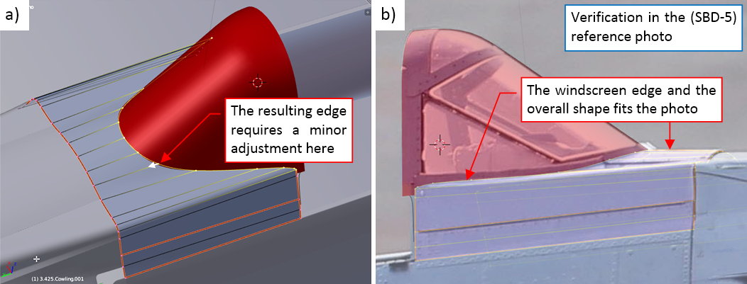
It is always good idea to check this shape in the reference photo (see figure “b”, above). Fortunately, it seems that my edge between the windscreen and the fuselage fits its real counterpart.
When I verified the basic shape of this panel, I extruded it into the “frame” strip that spans around the windscreen:
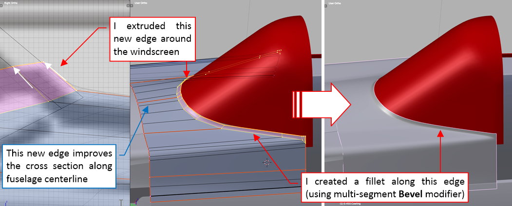
To obtain a shape that resembles the real part, I assigned to the intersection edge a multi-segment Bevel modifier. It produces a fillet that forces the Subdivision Surface modifier (applied later) to generate a more regular rounding along this windscreen bottom frame.
Finally I created the armor plates that were attached to this hinged cowling. It was an easy part: I copied corresponding fragment of the cowling mesh, then I used a Solidify modifier to make it thick enough (on the photos it seems to have just a few millimeters):
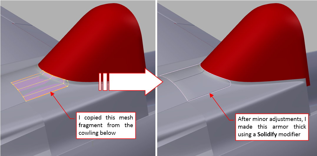
I think that in this armor I will use textures (bump texture, ref texture) to recreate the bolts and the circular recesses around their heads (as visible in the photos). However, I will do it during the next stage of this project.
The last element that I modeled in this mesh was the seam along the bottom border of this panel. It was stamped in the sheet metal to overlap the upper longeron of the fuselage (see figure “a”, below):
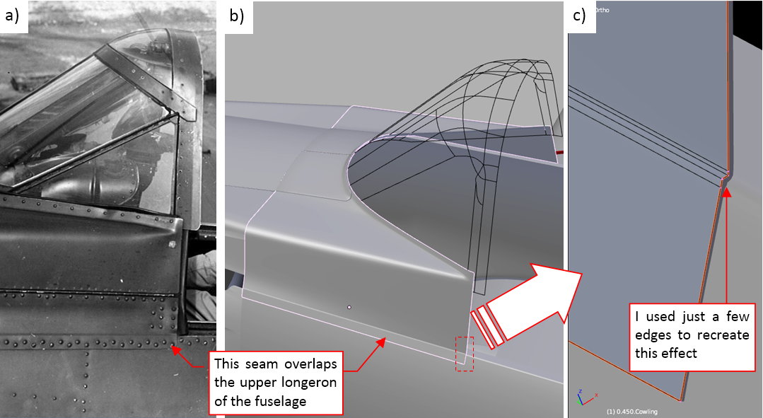
I also thought about recreating this detail in the textures, but ultimately I decided that it needs a more pronounced appearance. It is an easy effect (see figure “b”, above) that required just a few additional edges (as in figure “c”, above).
In this source *.blend file you can evaluate yourself the model from this post.
In the next post I will form the multiple segments of the SBD “greenhouse” cockpit canopy.
Like many contemporary designs, the SBD had a long, segmented (“greenhouse”) cockpit canopy. In this post I will show you how I recreated it in my model. I will begin with pilot’s canopy, then continue by creating the three next transparent segments.
I formed the pilot’s canopy by extruding the windscreen rear edge (see figure below). (I formed this windscreen earlier, it is described in this post). The high-resolution reference photo was a significant help in precise determining its size and shape:
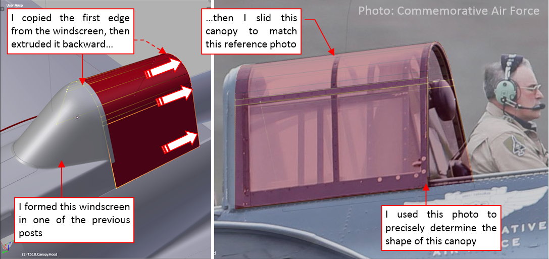
Generally, the canopy shape in the SBD is quite simple. The tricky part was that each of its segments slides into the previous one. (Oh, well, the pilot’s canopy slides to the rear, but it does not matter in this case). This means that there were clearances between each pair of neighbor canopies that permitted such movements. If I made them too small or too wide, the last (fourth) canopy segment would not fit into cockpit rear border (i.e. the first tail bulkhead)! In such a case I would have to adjust back all the canopy segments. Well, I will do my best to avoid such error.
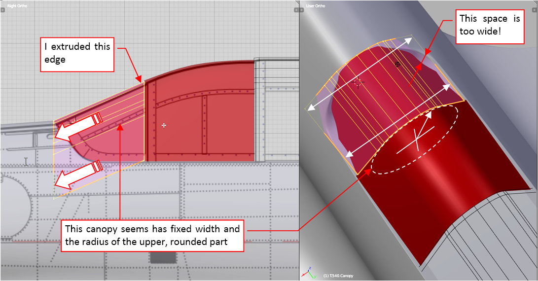
After the pilot’s cockpit canopy I created the next, fixed segment:
It was a fixed part of the cockpit canopy, bolted to the fuselage. I used the available reference photos to precisely recreate its shape. Of course, I also had to determine the distance between the sliding pilot’s canopy and this segment. It was a key moment: making it too narrow or too wide would spoil all further segments.
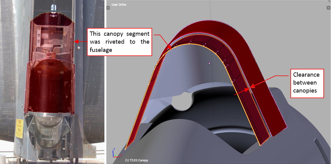
The photo references can be useful even when the modeled object is not visible: you can see such a case in figure below:
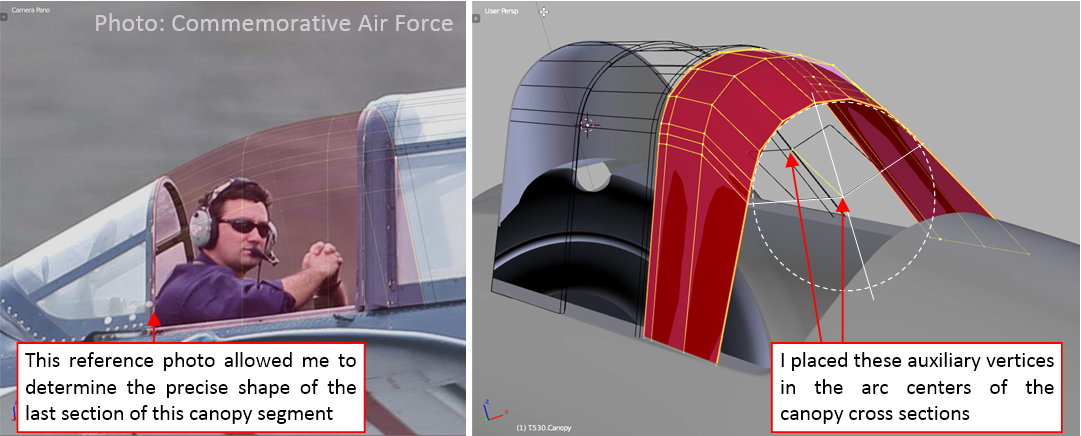
Although in the reference photo the gunner’s canopy is hidden under the fixed segment, the last canopy element is in place. Thus I used its forward edge as the reference shape for the rear edge of the previous canopy. The front edge of this element is deduced from the cross section of the previous canopy segment, offset inside by the clearance distance.
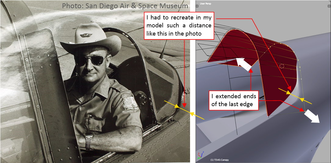
Initially I created the last canopy segment by extruding such an “offset” rear edge of gunner’s canopy:
The initial evaluation of the cockpit rear edge revealed that I had to extend a little the last edge of this object, to match the shape visible in the photos:
Of course, I also had to take care about the clearance between this and the previous canopy segment (see figure “a”, below):
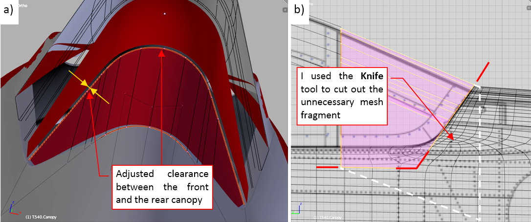
In the next step I cut out the unnecessary part of this mesh (see figure “b”, above).
Finally I recreated the rounded corner of this segment. I did it using an additional vertex, located on the bottom edge of the last mesh face. (See figure below. In this way that face becomes an n-gon). When I slide this vertex forward along the bottom edge, it reduces the radius of this corner. A movement into opposite direction enlarges it:
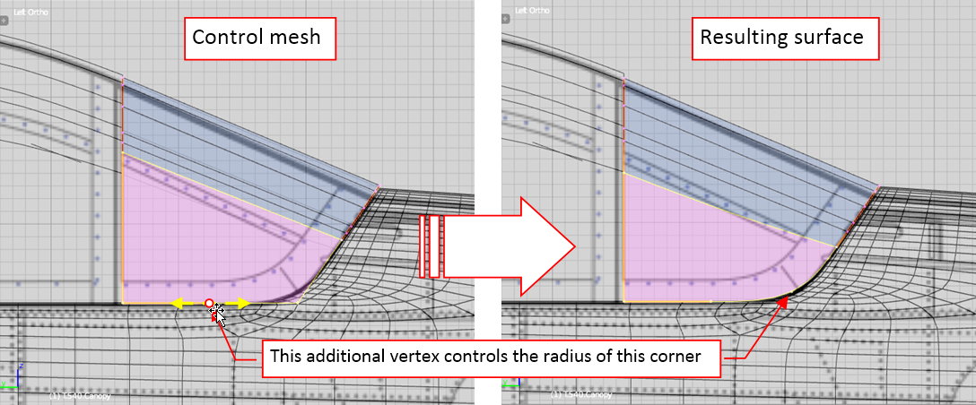
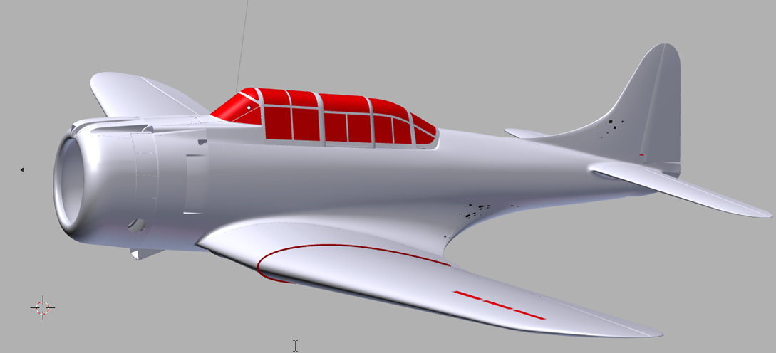
Figure below shows the complete cockpit canopy:
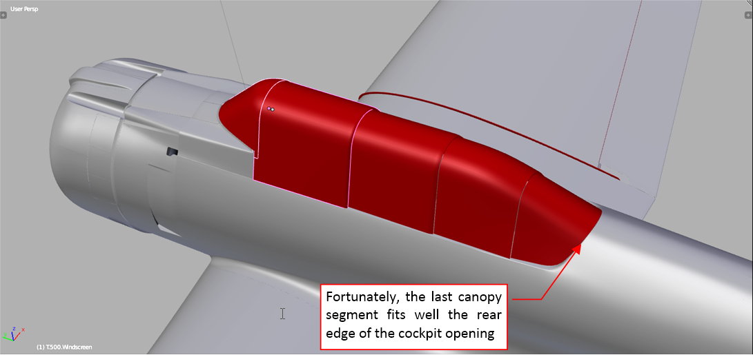
Fortunately, its last segment fits well into the cockpit rear edge, so I do not have to adjust all these canopy segments! (I mentioned such a possibility at the beginning of this post).
In this source *.blend file you can evaluate yourself the model from the figure above.
The shapes you can see in red in figure above will become the transparent plexiglass surface. I still have to place the sheet metal frames on these elements (I will do it in the next post). There were also internal tubular structures that supported these canopies from inside. I will recreate them during the last, detailing phase of this project
Today I will add the basic details of the cockpit canopy: its outer frames. However, before I started this work, I had to conduct yet another verification of the canopy shape. I placed the canopy rails on the cockpit sides, and verified if they fit the corresponding canopy segments. First I tested the rails of the pilot’s canopy (see figure “a”, below):
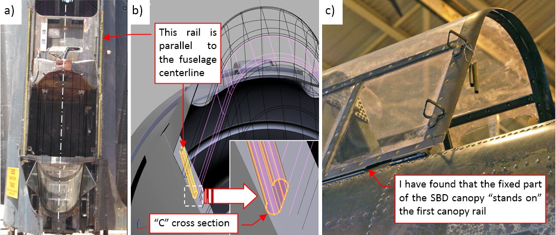
They were formed from open-profile beams (see figure “b”, above). Why these rails are such an important test tool? Because they always have to be parallel to the fuselage centerline! It sounds obvious, but it can reveal various unexpected errors in the canopy shapes. In this case I discovered that the fixed segment of the cockpit canopy was mounted on the pilot’s canopy rails. (In the previous post I assumed that this rail was placed between the pilot’s canopy and this fixed canopy). If I did not find this error now, it would cost me much more work during the later stages of this project! Now I could quickly fix it (see figure “b”, below).
In the rear part of the SBD cockpit you can find a double (two-beam) rail see figure “a”, below). The forward segment of the gunner’s canopy slides along the outer rail, while the rear (i.e. the last) segment — along the inner rail:
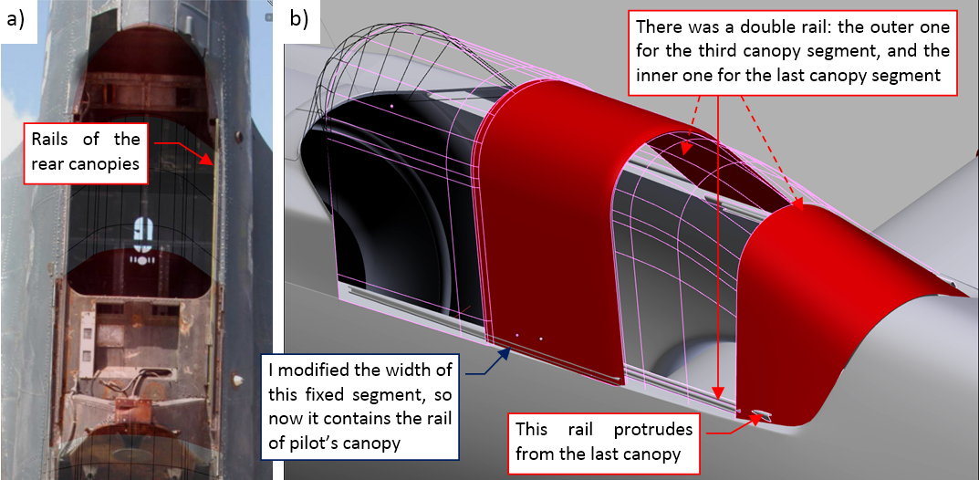
In figure “b”, above, you can see that this rail protrudes from the last segment of the canopy. It’s OK — in the real aircraft they cut out a half of its bottom edge, to make room for it (see figure “a”, below):
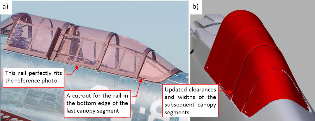
Frankly speaking, these rails forced a lot of small modifications along this “canopy sequence”. Their presence allowed me to fix various small differences between the reference photos and this model. In particular, now the roundings on the canopy rear edges match the photos, as well as the clearance between these canopies.
The typical cockpit canopy frame of a WW II airplane was a structure made from duralumin (or steel) tubes. In the SBD these tubes had rectangular cross sections, and were riveted to each other. They formed frames, which were covered with relatively thin (2-3mm) transparent organic glass plates. These plates were attached to the tubular “skeleton” by rows of small bolts:
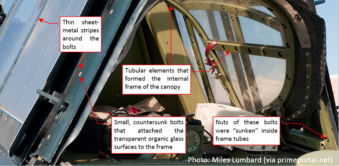
The heads of these bolts had flat (conic) heads, which were “sunken” in the thin sheet metal strips placed over the organic glass plates. (There was also a seal layer under these thin duralumin strips). In this post I will recreate these external sheet metal elements. The internal tubular frame of the canopies will appear during the last, detailing stage.
As the first I created the windscreen frame (figure “a”, below). The general method is always the same: I copied the mesh from the “glass” object, then cut out the frame stripes (figure “b”, below):
Of course, the subdivision surface generated by these strips in some places does not lie on the reference “glass”. Thus I had to adjust this mesh a little (as in figure “a”, below):
Finally I obtained the result as in figure “b”, above. Note that I created the frame of the hinged windscreen part as a separate object (just in case).
I formed the further canopy segments in a similar way. First I copied the mesh of the corresponding “glass” object. If it was required, I shifted it along its rails to match it against the reference photo (figure “a”, below):
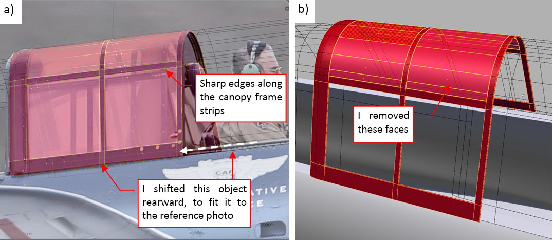
Then I inserted into this mesh additional, sharp (Crease = 1) edges along the borders of the frame strips that are visible on the reference photo. Finally I removed the unnecessary faces from the areas between these strips (figure “b”, above).
When the frame shape matched the reference, I shifted it back onto the corresponding “glass object” (figure “a”, below):
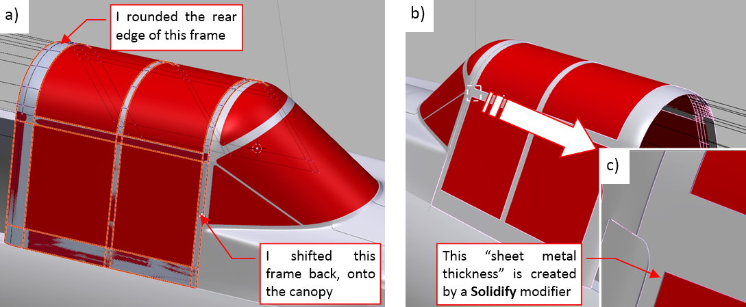
Finally I made this frame thick (by the “sheet-metal thickness” — about 0.02 or 0.03”). I did it using a Solidify modifier. It is directed outside, so it creates an illusion of thin stripes lying on the “glass” surface (figure “b”, above).
In a similar way I created frames of the all other segments of this cockpit canopy:
In this source *.blend file you can evaluate yourself the model from this post.
As you can see, this Dauntless model starts to resemble the original aircraft. However, it still misses the propeller. I will work on it in the next post.
The SBD Dauntless used two types of the Hamilton Standard propellers:
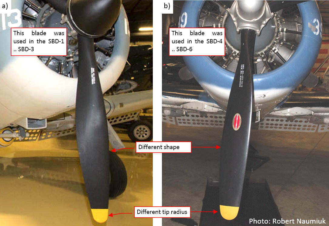
These two blades had different shapes. In this post I will recreate the earlier version, which was used in the SBD-1 … -3 (figure “a”, above). Several posts later I will modify its copy to obtain the later model of the blade, as used in the SBD-4 … -6 (figure “b”, below).
The main problem with recreating propeller blades of various historical aircraft is the lack of their precise drawings. In fact, I saw such a thing once, in the detailed plans of the Soviet WWII fighters. (Such a drawing contains the contour of the blade in the front and side view, as well as the set of subsequent airfoil sections, from the rotation axis to the tip). Nothing like this you can find for the typical Hamilton Standard blades! I looked for any trace of such drawings in the Internet. All what I found was a thread in one of the aviation forums. One of the participants of this discussion showed letters that he exchanged several years ago with the Hamilton Standard company. He asked for drawings of a blade that was designed in 1936. HS declined to reveal it, explaining that this design still remains their “business secret”.
In such a situation, all what we have are the photos of the real blades. (Until somebody makes a 3D scan of such a blade, and will publish it in the Internet — I hope that such a reverse engineering is legal). I used these references to draw the most possible blade contour in my scale plans. However, I had to rely on the photos for best estimation of the size and thickness of the airfoil sections of this blade, as well as the variation of their pitch along the span (i.e. propeller radius). Thus they may be less precise copies of the original than the rest of this model.
Now I see that I should draw the propeller blade vertically or horizontally on my reference drawings (see figure below). Well, I sketched them at the fancy angle of 120⁰, but never mind — it is still possible to use it. I will have to slide and scale the mesh vertices along the local axes of the blade object.
I started the work on the blade by creating a cylinder object. Then I rotated it by 120⁰, aligning to the reference drawing (as in figure “a”, below):
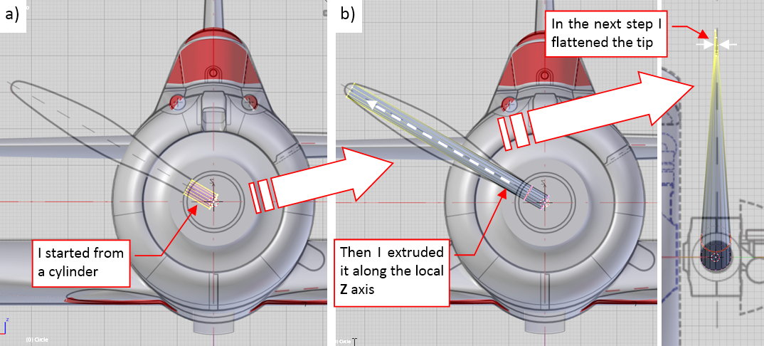
Then I extruded its upper edge and flattened it at the tip (as in figure “b”, above).
In the next step I inserted a few additional edges in the middle of this blade (figure “a”, below), and shaped them so they resemble a flat-bottom airfoil (figure “b”, below):
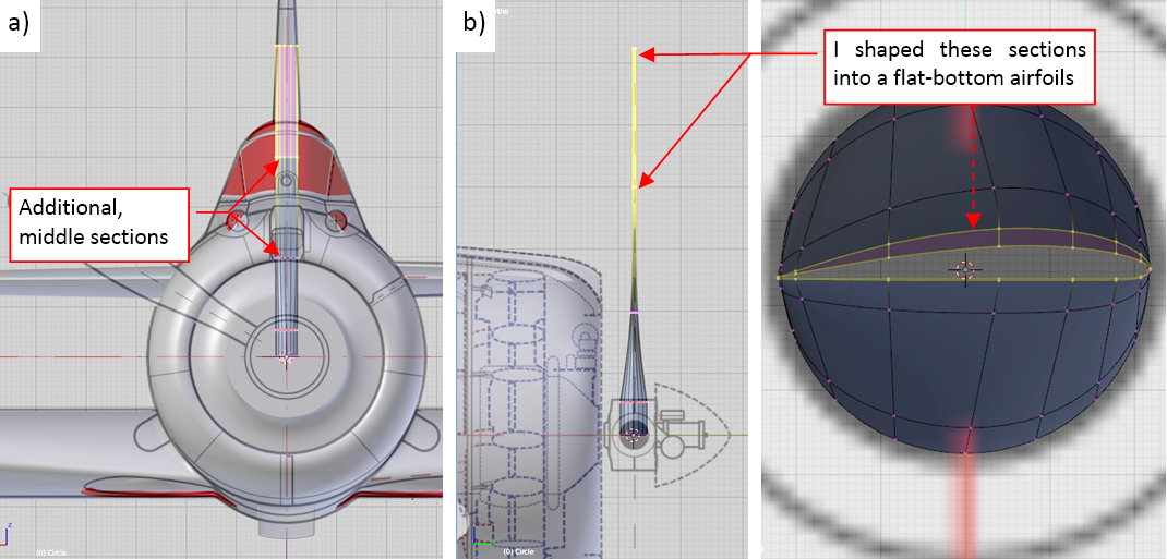
You can find such a flat-bottom airfoils in the most of the propeller blades. Why? Because their flat bottom edge creates a kind of technological base in this twisted, complex shape. (For example, it allows you to measure the local pitch).
I do not know what was the airfoil used in the Hamilton Standard blades. In one of the aviation forums I have found that it was RAF-6. It is not confirmed information. If it would be true, the leading edge of this blade should be sharper (RAF-6 had smaller radius of the leading edge).
When the cross-section shape of the blade was set, I started to form its contour in the front view:
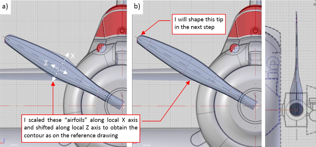
I stretched and shifted its airfoil edges until the blade contour fit the reference drawing. Figure “a”, above, shows how the base (i.e. control) mesh of this contour looks like. In fact, I formed it directly, using the alternative display mode of the smooth resulting surface (as in figure “b”, above).
Finally I closed this mesh along the circular tip. Comparing the reference drawing with the photos, I decided that the contour of this tip was a perfect arc. What’s more, I decided that it was a little bit larger than on my reference drawings. Thus I created a reference object — a circle (figure “a”, below):
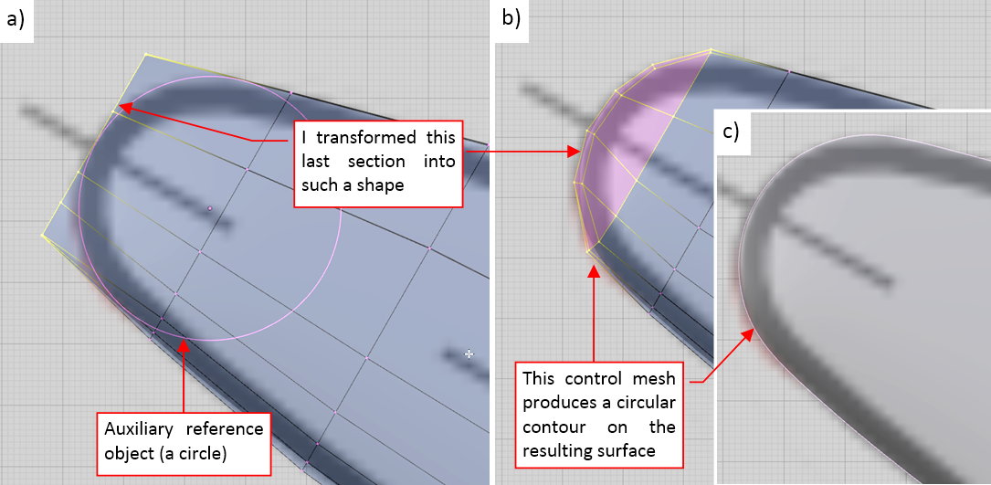
I modified the last edge of this mesh, shaping the resulting contour around the reference circle. Figure “b”, above, shows the final shape of the mesh, while figure “c” — the resulting tip surface.
Because I missed the information about pitch distribution along this blade, I decided to deform it in a dynamic way, using a curve via a Curve Deform modifier assigned to the blade object. In this case the deforming curve is a straight line, placed along the local Z axis of the blade (figure “a”, below):
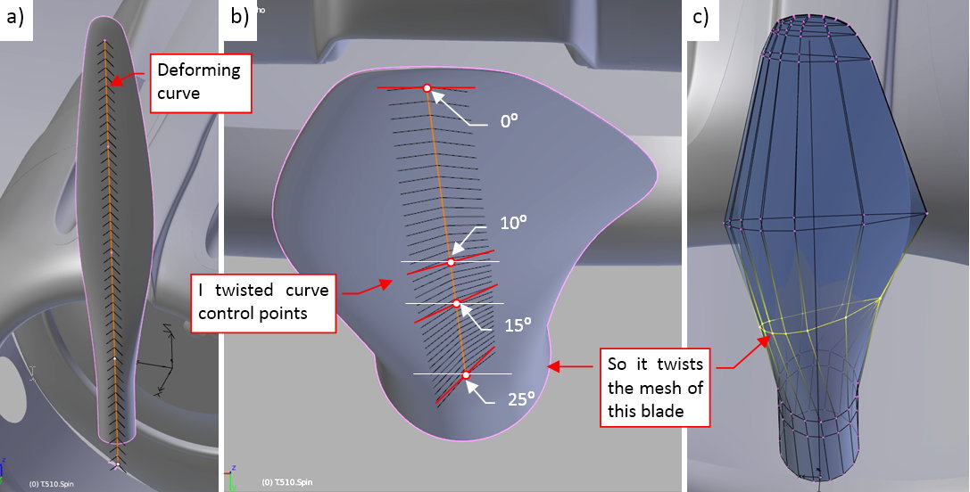
In such an arrangement I can control the pitch of this blade by changing the tilt value in the curve control points. At the tip the tilt is 0⁰, while at the last point (which lies on the propeller axis) it reaches the maximum value (25⁰). These values are just an estimation. The tilts in the middle points of the curve lie within this range (figure “b”, above). It dynamically deforms the control mesh of this blade (figure “c”, above). After a few trials I obtained the twisted shape that resembles the photos.
When you twist the shape using a modifier (like the Curve Deform in this case), you can easily switch into the original, untwisted shape of this blade. In this form you can easily introduce eventual modifications, like the sharper leading edge, or different shape of the tip. This feature will be useful when I have to create another version of this blade (for the SBD-5)
Figure below shows the three clones of this blade, arranged as in the propeller:
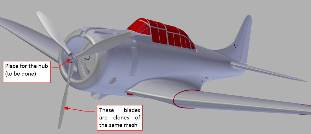
Their mesh is a copy of the original, with the “applied” (i.e. fixed) result of the Curve Deform modifier. Just in case, I preserved the original (not twisted) mesh of this blade together with the deformation curve in the References scene, among other auxiliary objects. It will be useful later, for the Hamilton Standard Hydromatic propeller, used in the SBD-5.
In this source *.blend file you can evaluate yourself the model from this post.
In the next post I will create the hub of this Hamilton Standard Constant Speed propeller.