Hi;
You are doing a great job. BUT, Knowing me, all I see after the fact is lots of greeblies for scratch building. Maybe it’s worth the price just for that? I am not kidding. But all in it’s proper place, your work on this beast is awesome!
Hi;
You are doing a great job. BUT, Knowing me, all I see after the fact is lots of greeblies for scratch building. Maybe it’s worth the price just for that? I am not kidding. But all in it’s proper place, your work on this beast is awesome!
Hi
This too; Do you have a Butchers supply shop nearby. It’s actually more like a Restaurant supply house now. Get a Cook’s apron and use that Then put some snaps on the bottom corners and snap to the table edge
That’s a good idea too. Right now the drape I’m using is working. I dropped two tiny PE parts and it caught them with no fuss.
The Turret basket is fully detailed and installed in the lower turret. And the lower turret is glued to the upper turret. You really can’t leave these two loose becasue it’s a bit fussy getting them to key together and it would break stuff if you did it too often. At least having the turret removable would let you see all the cool stuff from underneath.
I attempted to use the little PE rings for the ends of the six cartridges in the “ready rounds” box, but they were such a pain to install (read that…failed!) that I used my chrome pen/clear yellow treatment to make them look metallic.
After looking a lot of interior images last night I saw that some of the appliances were not white and I altered the color-scheme to reflect this. The handgrip is the power traverse control.
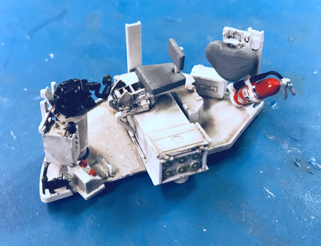
It was time to glue this complicate thing to the turret bottom. Incidentally, the M4A3 76W was the only Sherman to have this truncated basket floor. It was necessary to access the magazine that was now below the floor. The turret had to be rotated to the proper position to open to that place. I imagine the loader would grab some rounds and put them in the ready box since once the turret was rotated, the magazine may not be accessible.
I didn’t even think about using solvent cement to hold the three support posts to the ring edge. I went directly to medium CA and accelerator.
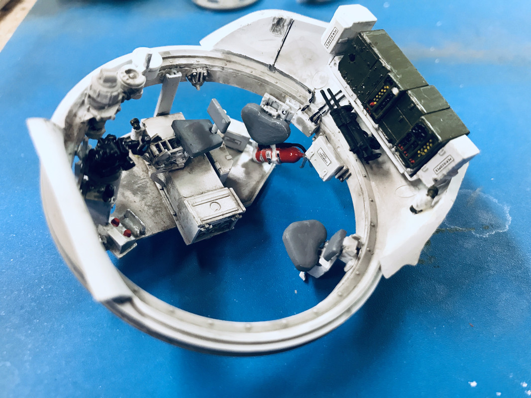
I then glued this whole deal to the turret top. And then I attempted to glue in the commanders seat. I can understand why they had you glue half of the seats supports to the bottom first, but frankly, getting it to settle into the hole in the top half seemed dubious to me, so I held off and put the seat in place when the turret was whole. It took a couple of tries and then I resorted to tube cement since the solvent stuff just wasn’t cutting it. I inserted the seat through the commander’s hatch opening. I tried from both directions, but this one was the best.
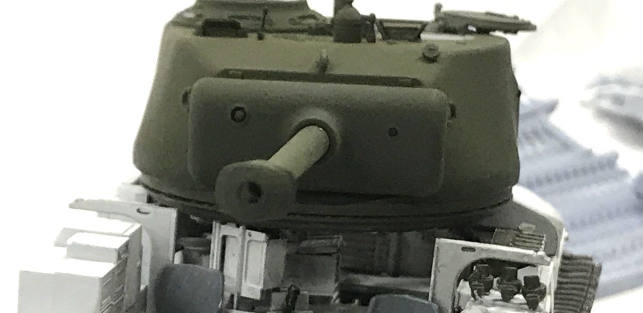
I kind of munged up the turret walls, but it actually makes it look more real (to me). This is a hugely enlarged image.
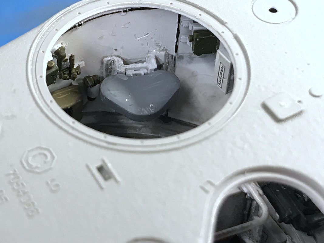
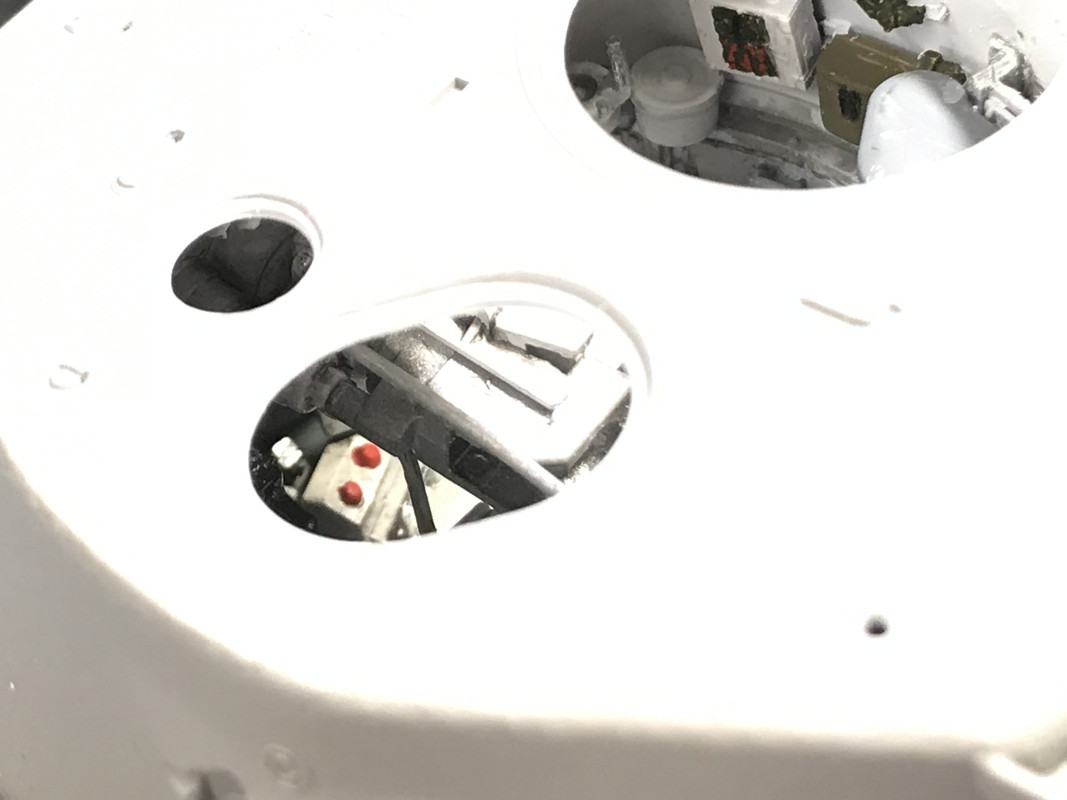
I took some shots looking into the various opening to see what you can see. Unfortunately, the iPhone camera can’t resolve the contrast ratio that our eyes can. To expose the interior to see it, I had to expose the outside surface. You can see some things if you pay close attention. This is the right side of the gunner’s station.
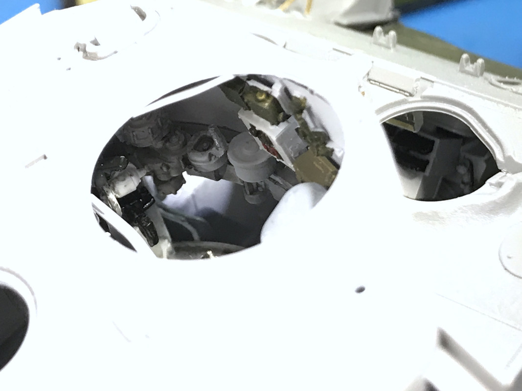
Here’s looking through the loader’s hatch and you can see the two firing switches.
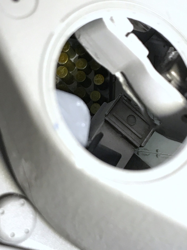
Lastly here’s as much as you can see of the main gun and the open ammo magazine lying below the floor pan.
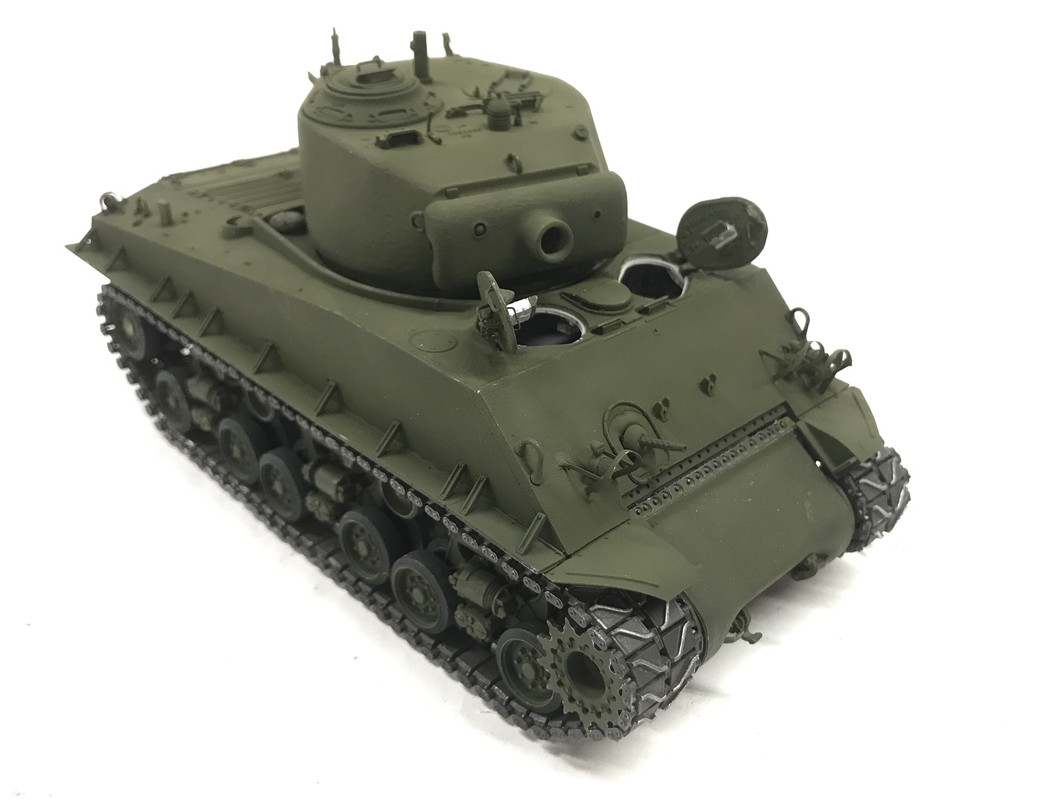
The turret just plopped perfectly into position on the tank body. I was happily surprised to see the basket lug drop right through the hole in the floor. On the real tank, that lug contained the contacts and slip rings to get power to all the turret equipment while letting the hole thing rotate through 360°. It even cogs when you rotate it with the ring gear teeth actually providing some tactile feeling.
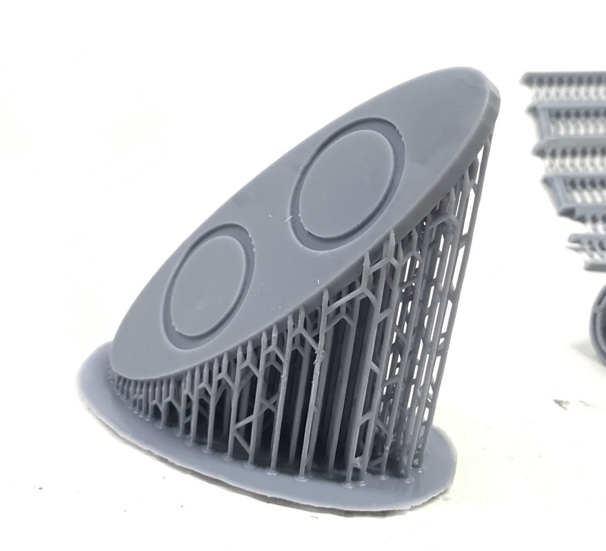
Before I get into tank production, I’d like to share a holder to prevent Microsol and Microset from constantly spilling. I drew this on SketchUp and printed it on my Elegoo Mars Resin 3D printer. The tubes and the base are separate parts which enabled me to print them with a minimal amount of supports. I grew the base traditional, on an angle with lots of supports on the bottom (actually the top since it prints upside down) and then printed the two tubes directly on the build plate with no supports at all. I designed a recess into the base that the tubes slipped into. I glued it together with the same resin from which is was created. The resin was cured in the UV Curing Box that I use to finish cure the objects. When objects come from a resin printer, they are about 3/4 cured. It took about 40 minutes to fully cure the object since the light had to penetrate deeply into the object. To 405nm UV the object almost appears transparent.
Here was the base as it came on the printer.
And here’s the finished product.
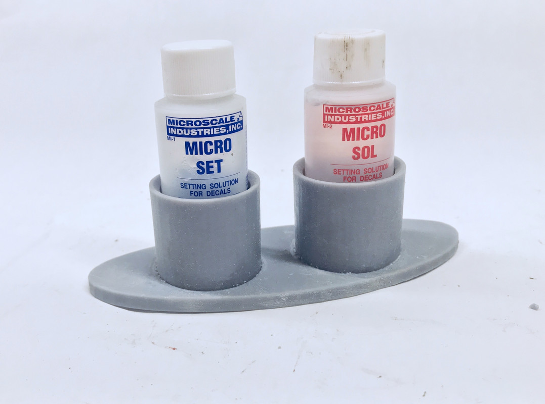
No more spilled Microsol products. As I noted in an earlier post, I never use this stuff up, I always ended up spilling it. I resorted to clamping the bottles into a woodworkers vise to keep them upright. Now I don’t have to worry about that.
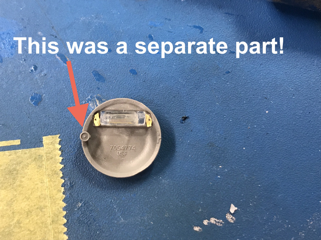
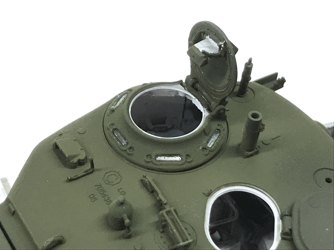
I exercised today so my work time was curtailed a bit. I did work on the turret top details. The rotating periscope ring had the capability to actually rotate if you were nuts. I chose to glue it in the forward facing position. You were supposed to glue the inner periscope holder to the hatch only contacting a 1/64" wide PE ledge. You were supposed to captivate the PE ring with the holder and NOT get any glue on the hatch itself. It was fundamentally impossible. And this was the size of one of the separate detail pieces.
And notice too those tiny PE pieces supposedly being the clamps that hold the periscope in place. Ridiculous!
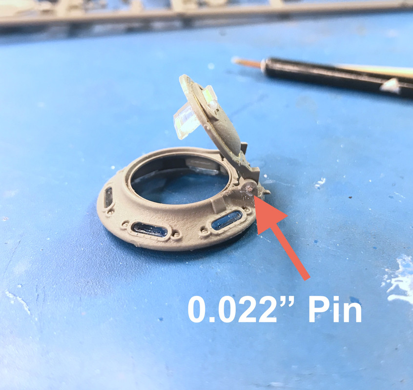
The loaders hatch also had provision to make it openable with a little plastic piece that captivated two little hinge pins. I was able to make this work. But, surprisingly, the commanders hatch itself DID NOT have provision for hinging. So I made it myself by cross-drilling and inserting a piece of 0.022" phos-bronze from both sides. The hatch now operates.
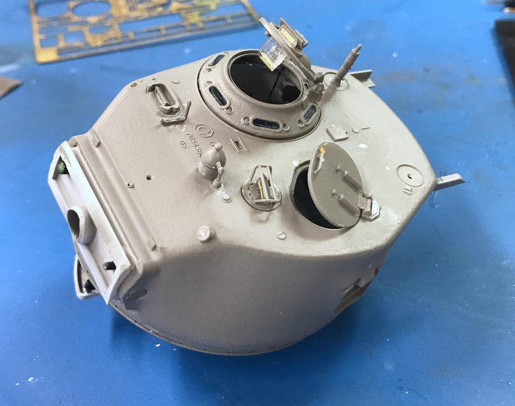
I added a couple more doodads on the turret top. I also filled the one seam that ran around the turret back with Tamiya Putty. The commanders hatch lid interior is probably O.D. like the front hatches so they don’t flash white when opened, but the inside of the rest of the commander cupola would be which. I think the loader hatch too should be O.D. on both sides for the same reason. I also built the loaders periscope which gets glued in its own hole. Notice too the tiny PE angles on both sides of the loader’s hatch. Looks like it could take a little tiny 1/35 Master Pad Lock. Cupola and Loader Periscope are not yet glue in.
That’s a good looking decal setting solution holder. I always brace mine in a box with the edge on one side and some tool on the other to keep them from flipping over. Your solution is much more elegant!
And the detail there is incredible. If I were a surgeon or a watchmaker I might try to make the parts workable. But I’m not so I agree with you!!!
‘Dammit Jim! I’m a modeler not a doctor!!!’
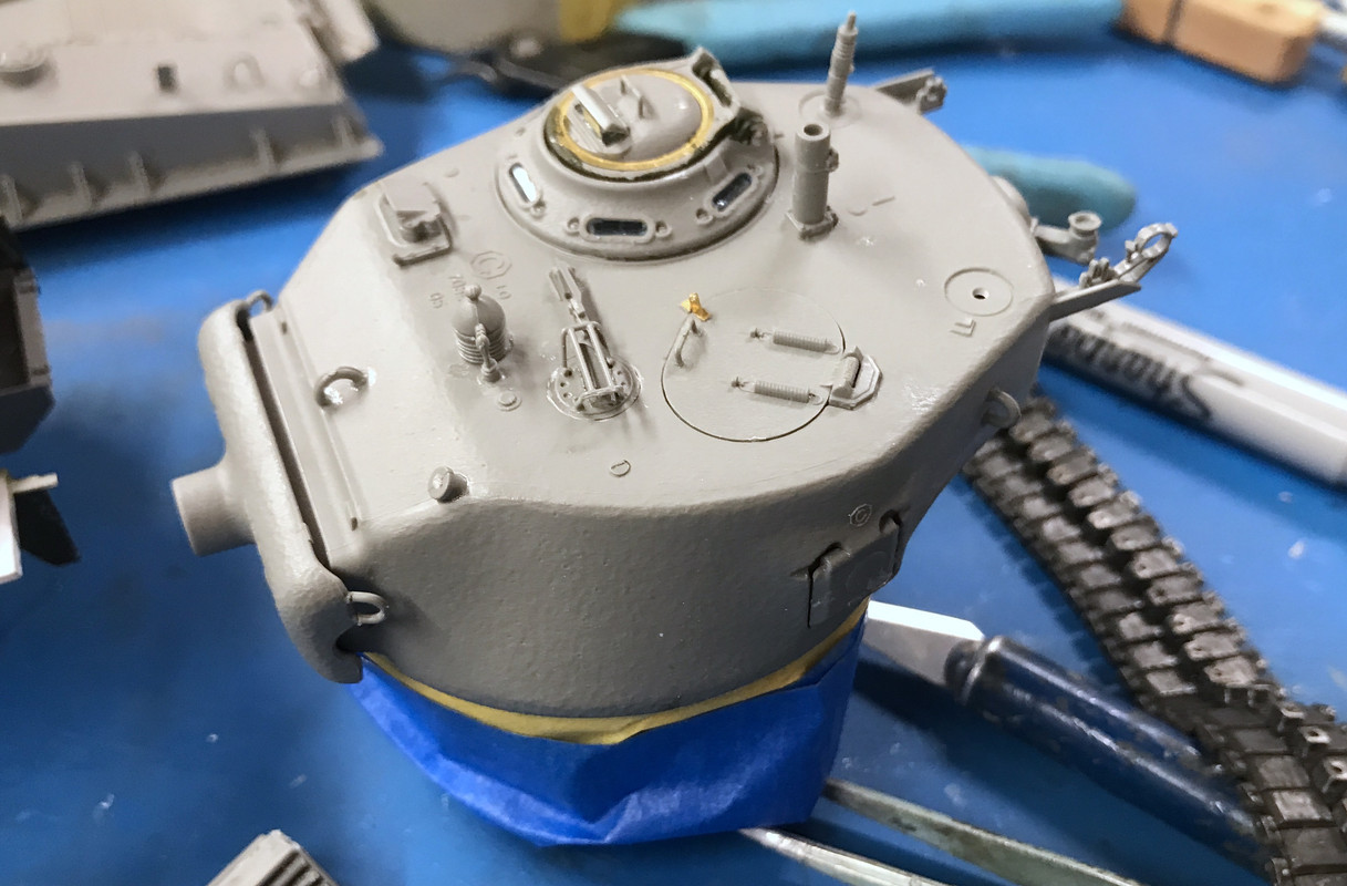
Today’s session was two steps forward and one backward. I got all the interior painting on the upper hull done and brush painted the inside of the hatch lids O.D. or white depending on their use in getting ready to paint the exterior. I detail painted the periscopes with the bare metal sleeve and the O.D. heads. And I got all the rest of the doodads on the turret.
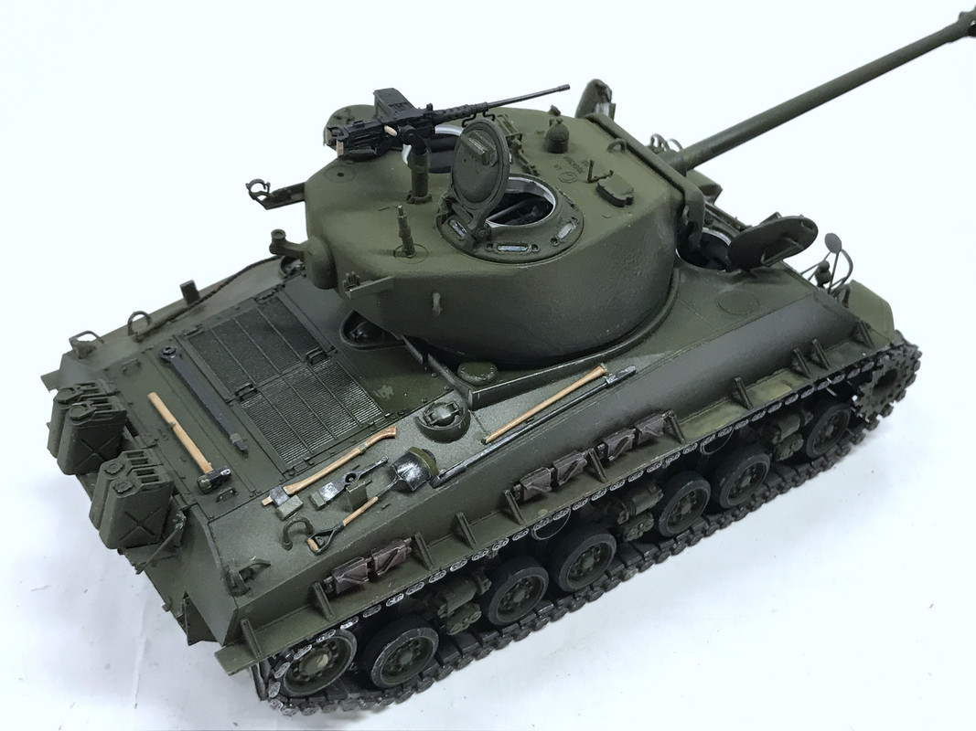
You see that lift ring on the mantlet. That little SOB cost about 20 minutes of aggravation. Again, Ryefield doesn’t provide a seriously deep pin hole or a reasonable pin to go into said hole. Therefore, I was wrestling with this little part until almost destraction. It keep rotating in my tweezers and getting stuck in the wrong position. Persistance paid off and I got it in place. As usual the second one went much faster. Incidentally, these rings were not to used to lift the turret, only to help to remove the gun from the tank. The movable hatches are closed, but not glued so I can open them after painting. At the turret rear are faux spring clamps that would be used to hold the 50 cal in its stowage position. I’m putting the gun deployed. They’re also delicate details.
I forgot to photograph the inside of the hull and it’s now fully masked for the exterior painting.
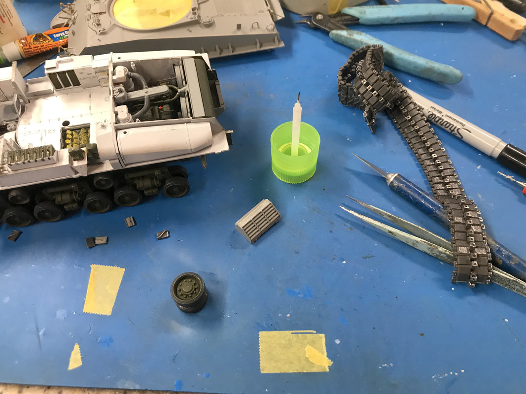
Then there as a radiator guard system that hangs on the rear of the tank. This was another ridiculous assembly since the part is glued to only one edge at the rear and then is suspended with a single very thin plastic rod. I got the parts transposed since there is a left and right, and the notch to receive the rod was in the wrong position. I made a new notch. But in the constant handling of the tank, one of the tracks decided to shed those annoying tread pieces. I had to break the track apart, force off the idler wheel and get ready to rejoin it on Monday. It was a definite bummer!
In this picture you can see, the armored radiator guard (left side) the track and the little bits of tread pieces that I must now re-attach. Nothing broke, it just fell apart. I said before that the track assembly process is not very robust and here’s a good example. The radiator shields also are supposed to glue onto the back place of the upper hull which would give them much more purchase and strengthen their attachment. But… and it’s bit BUT, that would mean permanently attaching the upper hull to the lower and I’m not going to do that especially since I have provided no way to view the beautiful engine by gluing the engine covers in the closed position. They’re just going to have to hang there and be delicate.
Ouch, looks like you’ve got things in hand though!
I’m flattered by the confidence you have in my abilities. Hopefully, I won’t disappoint.
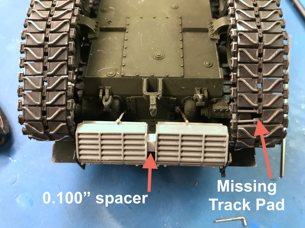
I finished installing those pesky radiator shields. Since they’re not going to be affixed to the upper hull, they were not stable. They’re only glued on a thin line on their outside edges, and then there’s that truss rod that goes to the lower hull rear plate. Without gluing to the upper hull they sagged downwards and inwads. I needed to cantilever them against one another and that required a 0.100" styrene spacer. With this glued to both shields, the truss rods and the edge glued, they became self-supporting. I also lost one of the truss rods and had to cobble one using some 0.022" phos-bronze rod. It’s a minor detail and needed to be there for support.
Notice that I did get the track repaired and replaced on the tank, and then I lost another track pad. Unlike when I reconnected the track off the tank on the fixture, this time I had to replace the tread pieces on the tank since the other hald of the link was still intact. I was able to roll the track to a place where one of the road wheels was directly under the missing tread so I could put some pressure on the glue joint to set it. The first attempt I didn’t hold the pressure long enough and the track separated on one side. The second try was successful and the tracks are one again fully intact.
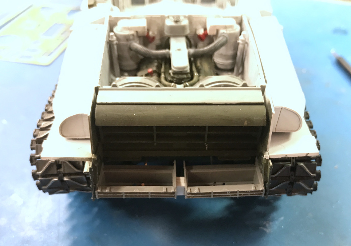
From the top, these are just hollow plastic parts that don’t make sense unless the upper hull is in place.
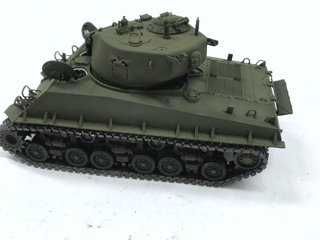
With this part in place, I was able to paint the upper surfaces. I started painting the NATO Black undercoat and then abruptly stopped. I hadn’t masked the head and tail lights. I used MicroScale Liquid Mask to do this and then continued painting the black. The color dried quickly and I put on the next coat of regular Tamiya O.D. followed on with a coat of my aged O.D. mix (O.D. and Khaki) to highlight panels.
When dry, I glued the hatches in the open position. Prior to doing that I had to do some extensive work on those hatches. One of the periscope shields fractured and didn’t respond well to re-gluing. I also lost one of the exterior hand grabs. I replaced the hand grab with phos bronze and replaced the destroyed periscope shield with one of the kit’s PE ones. It actually took two to get it right. I brush-painted the damaged areas O.D. and then did the same to trim the edges of the hatch openings. I glued the hatches in with Med CA.
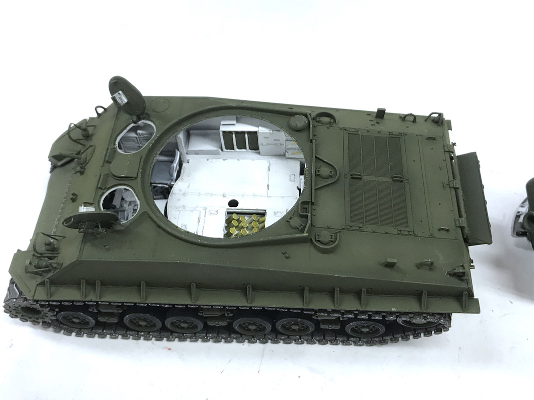
The paint looks okay. I had to brush paint the bearing race area of the turret since the masking was too severe. One of the reasons why gluing the upper hull on is counter-indicated is that fit at the gear case cover. The upper hull is supposed to slide under that row of bolts on the cover. It does not want to go and I’m afraid I would break something if it forced it. I took of some of the vision pieces masking, but not all. The turret’s pieces are still masked, as are the fixed periscopes for the front crew. There are miniscule rear view mirrors that get mounted on a more miniscule PE bracked. I’ve left this off until last since it is sure to get whacked and broken.
I have to prepare and install all the tools and the tow cable, plus the extra tread pieces that go to the side of the upper hull. All the hatches will be open including the gun port on the turret side. It’s not glued.
Tonight I’m going to design a set of display holders to show the upper hull and turret in positions so their undersides will be visible. I’m going to 3D print them. I almost hate to have to gloss coat all this beautifully flat paint so I can use panel accents. Can’t use them on flat surfaces. There are also some more decals that need to go on. The end is near.
The Sherman looks amazing! I’ll say all the work you’ve done on this kit has inspired me to finally finish my Dragon Sherman that’s been on the shelf since April.
I’m glad I inspired you to get into action. I have a friend here in Louisville who’s very active in community stuff. I said to him the other day that he’s so busy doing good deeds and all I’m doing is working in the basement building stuff. He reminded me that all the articles I’ve written and the forums on which I am a very active contributor is affecting people positively too. I shouldn’t sell myself short. So your comment reaffirms that belief.
I started today with building and installing the big gun. It doesn’t get glued in. It’s a press fit. There’s a spring that goes in first and the gun and the receiver actually recoil. Before that it had to be assembled. There’s the barrel, and the flash suppressor. The suppressor consist of four styrene and two PE parts. The PE is basically invisible as a series of two toothed rings that go between the front plate and a plastic ring. The back of the suppressor housing which simulates the muzzle end actually has some rifling grooves, but they too are really hard to see. I painted the gun while mounted in the turret and used more of the weathered O.D. on the top surfaces than the bottom simulating some mild fading.
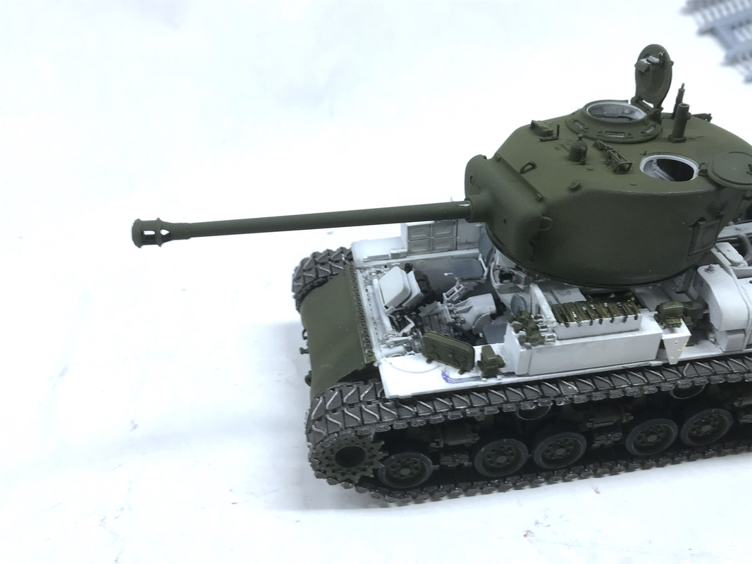
Only one problem. When I tried the recoil it peeled the paint off the barrel at the slide end. I’ll touch it up later. I did some research on these appliances and found their main function was to reduce the recoil by venting combustion gases out sideways. This was necessary to use the 76 mm higher velocity in the same turret. If it didn’t have the suppressor the recoil would have pushed the gun too far back. This was one of the main limitations on simply installing larger and larger guns.
I hand painted all the track tools while still on the sprue. I’ll have to touch them up after installation to cover up the sprue nubs. These will need a little more work to make them really good.
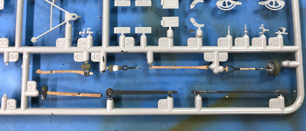
I also took the time to paint the spare track links that flank the outer hull.
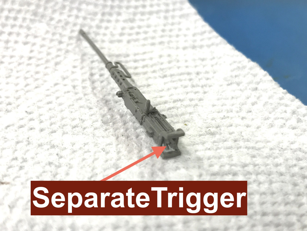
I built the 50 cal Browning. This was major assembly comprised of 17 parts. It is extremely delicate. I’m letting dry thoroughly overnight before painting.
This picture shows the separate trigger, hand holds and cocking lever.
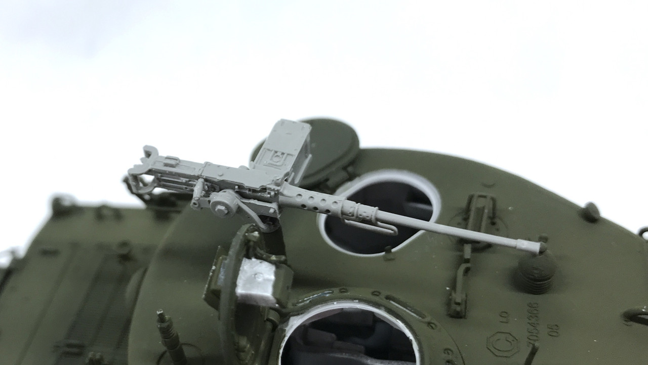
There’s parts for several ways to mount this gun: on a tripod separate from the tank, in the pintle on the turret roof (as I’m going to do) and in separate pieces stowed in the clamps on the turret rear.
Here’s the finished gun waiting for paint.
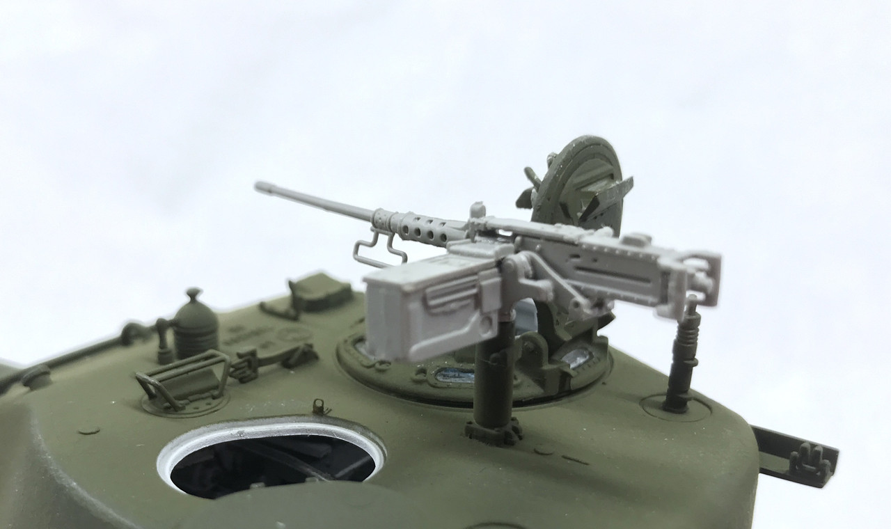
The fit in the pintle was a bit tight meaning I would have to apply too much unwanted pressure onto the delicate gun, so I checked the spindle size in a drill gauge and opened up the pintle with a #53 drill. It’s now a nice slip fit.
I really haven’t built many armor kits by the new manufacturers so even though I think this 50 cal had a ton of parts, it may be normal. You’ll have to tell me. It seemed to be a bit excessive and this leads to it being really fragile.
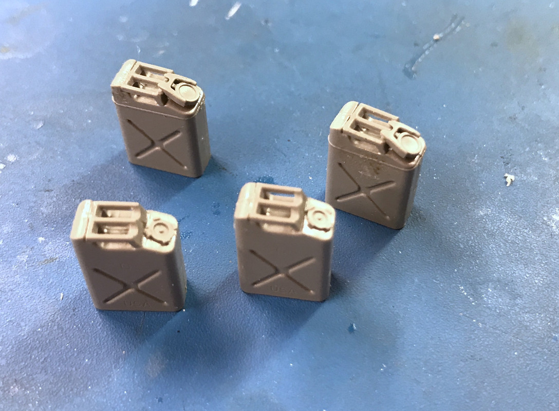
Even the Jerry cans are a big deal. The kit has two distinct types and they have four parts each. One style has a small ridge around the top, the other is plain. And they have two different kinds of caps. The only thing in common was the handle and that too was separate.
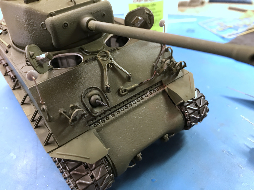
The last thing I installed was the gun’s travel lock (in the down position). Tomorrow I’ll continue with adding these details Even the tow cable is a big deal being held to the tank with some micro-PE clips.
I also removed the liquid mask from all the transparents including head and tail lights and vision blocks. Regardless of my concerns with this kit’s difficulty and crazy engineering, you have to give them credit for the mold accuracy. Notice that the “screws” holding in the vision blocks actually have clearly defined slots in them.
Till next time…
Seventeen parts for the .50 caliber seems a little excessive to me, but it looks very good. About 10 parts is average for a decent looking Ma-deuce IMHO.
I thought so too. Today is the beginning of the end. I got all the remaining details onto the tank, did the panel accent treatment, and put on some limited amounts of gloss in preparation for the limited amounts of decals.
The first details to be applied were the extra tread pieces and the tool sets. The treads got some rust-colored weathering powders.
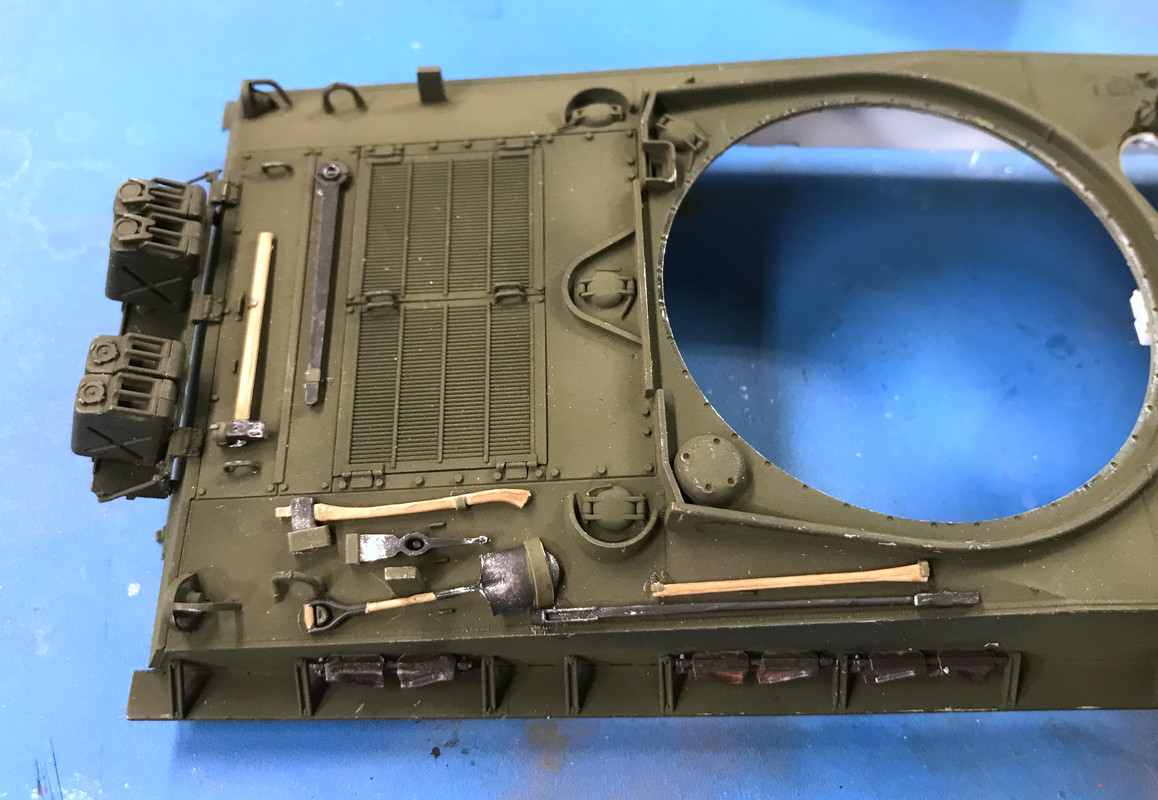
Notice too I painted and mounted the four Jerry cans. I have not added any fuel stains or spills yet. I’m happy with how the tools look. I used small drops of med CA to hold them in place. They’re probably very fragile being that the CA is basically holding onto three layers of paint and not welded to the styrene base.
I then got the 50 cal painted and waiting for a decal on the ammo box. I use the Molotow Chrome pen on the muzzle end just for effect. I added a little gloss just to the gun barrel to give it some contrast with the receiver.
The tow cable is a thread and two styrene ends which I med CA’d onto the thread. It then gets attached to the hull via a very tiny little base piece, a piece of bent PE and a very tiny wing nut. I lost one of the base pieces and after looking for it, made one out of 0.030" X 0.030" styrene. After getting it all done, I found the missing piece in my catch cloth. I actually checked there first, but the piece was so small as to be nearly invisible. Since I had already replaced it, it was now moot.
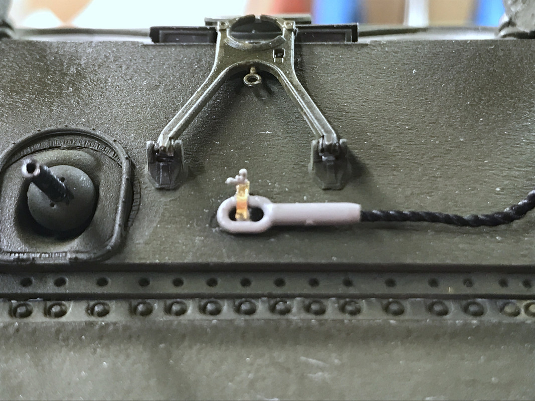
The cable was supposed to belay onto the gear case. But if I put it there I wouldn’t be able to remove the upper hull which is NOT glued. So I relocated it to the hull space above the gear case. Not prototypical, but pragmatic for my purposes.
This picture also shows the scratch-build rear view mirror installation. The plastic shafts somehow glued into a tiny folded PE bracket was a non-starter. Furthermore, one of the two shafts was already fractured in two while still in the sprue due to stresses imposed by a huge ejection pin defect right next to it.
Tomorrow, I will use the Molotow pen to apply a nice reflective surface on the viewing side of the mirror.
So all the little bits are on the vehicle. I used Tamiya Clear Gloss to selectively airbrush areas where either decals are going or I wanted to use the black panel accent treatment. This was specifically the engine grills shown below.
Notice also the the 50 cal is done. I painted the cocking lever and hand grips my wood color. Also I opened the gun port of the turret side since this was not glued in.
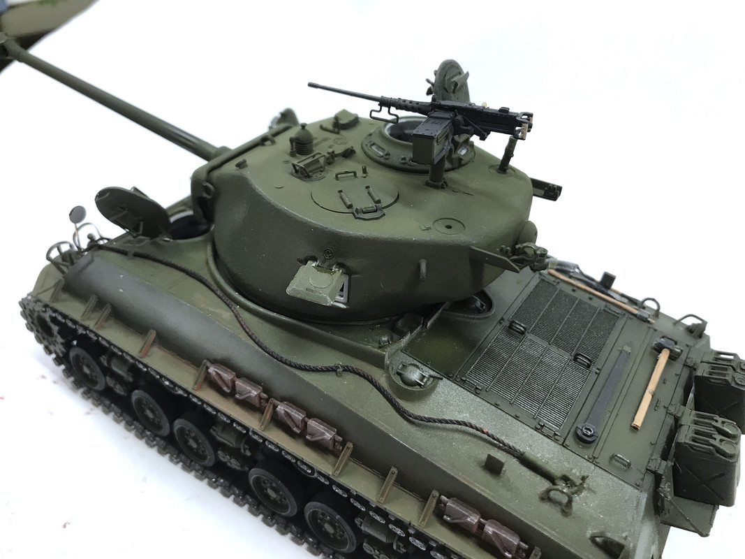
I used some black weathering powder on the muzzle end of the big gun, but it doesn’t show up much. I may go back and just kiss it with some flat black finely airbrushed.
After decaling I will go back and flat the tank to seal them and even up the sheen. I’m still working on a display support. There’s no rush since the tank can sit on the shelf as it is.
Again, simply fantastic job there! Love the tools and the .50 cal. And the overall finish looks great too!
I think it’s a rule somewhere. If you lose a part and you buy or fabricate a replacement the missing part will always re-appear.
Very nice work on the tools and the .50 cal. I’m really impressed with how quickly the kit came together as it would take me at least a year to finish at my working pace.
Thank you! You have to remember, I’m retired and my “job” is building cool stuff in the basement. I put in 2 to 4 hours most days in this endeavor. I don’t work on weekends as you all know by now, but it’s still really satisfying that I can work on stuff like this at a reasonably steady pace.
So…on July 27 I started this project with box with over 1,900 parts in it and now there is this…
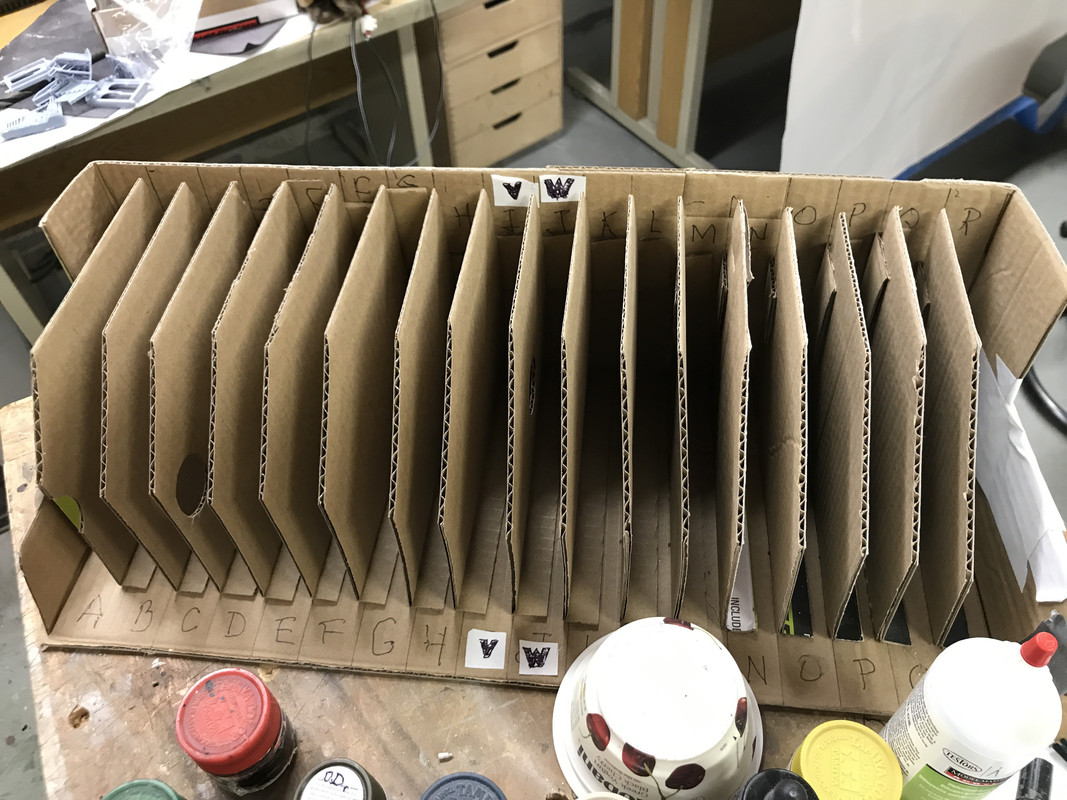
The parts rack is empty. And you know what that means? The model is done! I started assembling the crew set, but I have my doubts as to its usability. I built the one seated figure that could possibly go inside. He fits… sort of… it seems a little big, and he would be a loader since his hands are positioned to handle a round. The loader sits with his legs dangling into open space so there’s not much supporting the figure. His head is almost out of the hatch, but not quite.
I’m also having trouble printing a workable display rack to show the hull and turret in a position so you can see underneath.
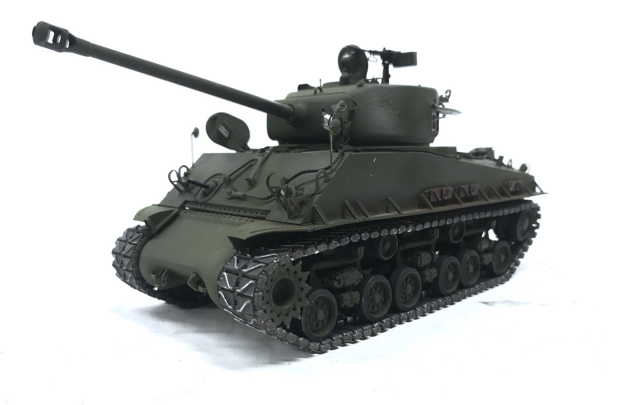
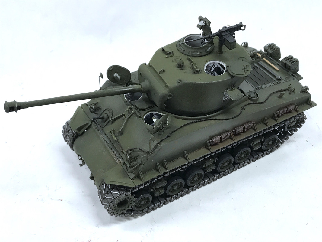
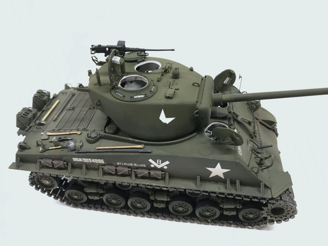
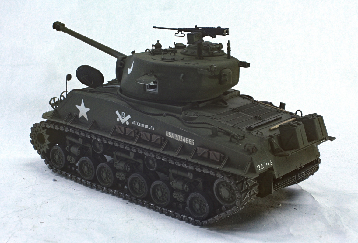
Be that as it may… the model I’m declaring is finished! Here are some of the final shots. I’m not taking any more interior shots since the insides have been done for a while. I tried to take a picture showing how reflective those rearview mirrors are, but it didn’t work.
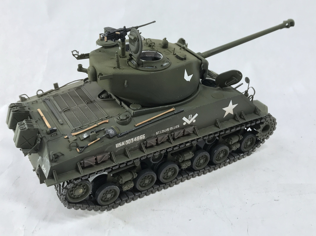
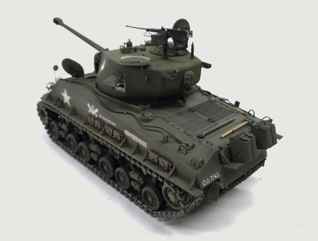
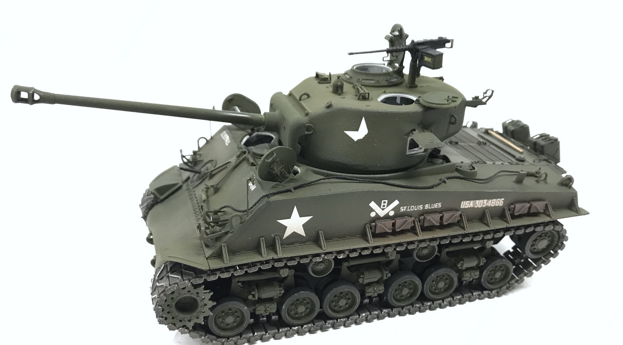
These two shots were done with my Canon EOS Rebel and Zerene Stacker image stacking software. Once again, the little camera on my iPhone 7 is actually producing more pleasing images. I’m itching to get the iPhone 12 when it comes out, and the Canon will probably go to the thrift shop.

So that’s that. In summation: this was the most complete, intricate and challenging plastic kit I’ve ever done. Now I have to add that my Missouri and Essex projects were huge and took longer, but most of the complexity was driven by me wanting to add to the kit with 1,000s of pieces of aftermarket PE, mods and scratch-building. The box kits themselves weren’t all that complicated. This one was complicated and difficult out of the box. It was over-engineered and multi-part assemblies which added complexity without adding much more in clarity. One of the most difficult and ambiguous assemblies was the gluing in the gear case and interior front end to the hull bottom. I may not have gotten this correct since the upper hull does not slip under the faux bolt lip on the gear case. There doesn’t seem to be room for it and I would definitely break something if I attempted to get it into there.
The treads, which I dealt with in great detail, are frankly, frightening. The fact that they’re still together and look so good is remarkable and surprising.
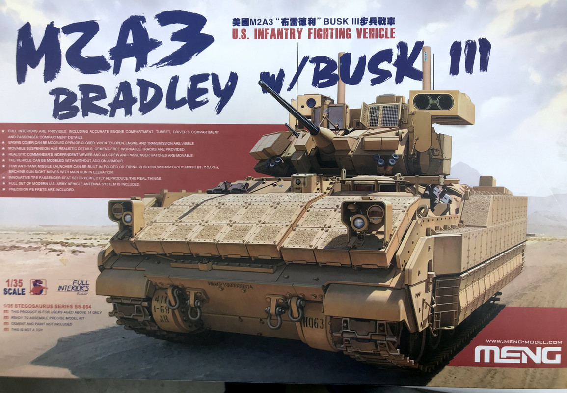
But, I never shrink from a challenge, and wanted to build one of their kits. My next plastic kit is up in the air, but as I noted before, I may try my hand at the Meng Bradley with the full interior. And I may be a glutten for punishment because I still want to built Ryefield Model’s A-1 Abrams with full interior too.
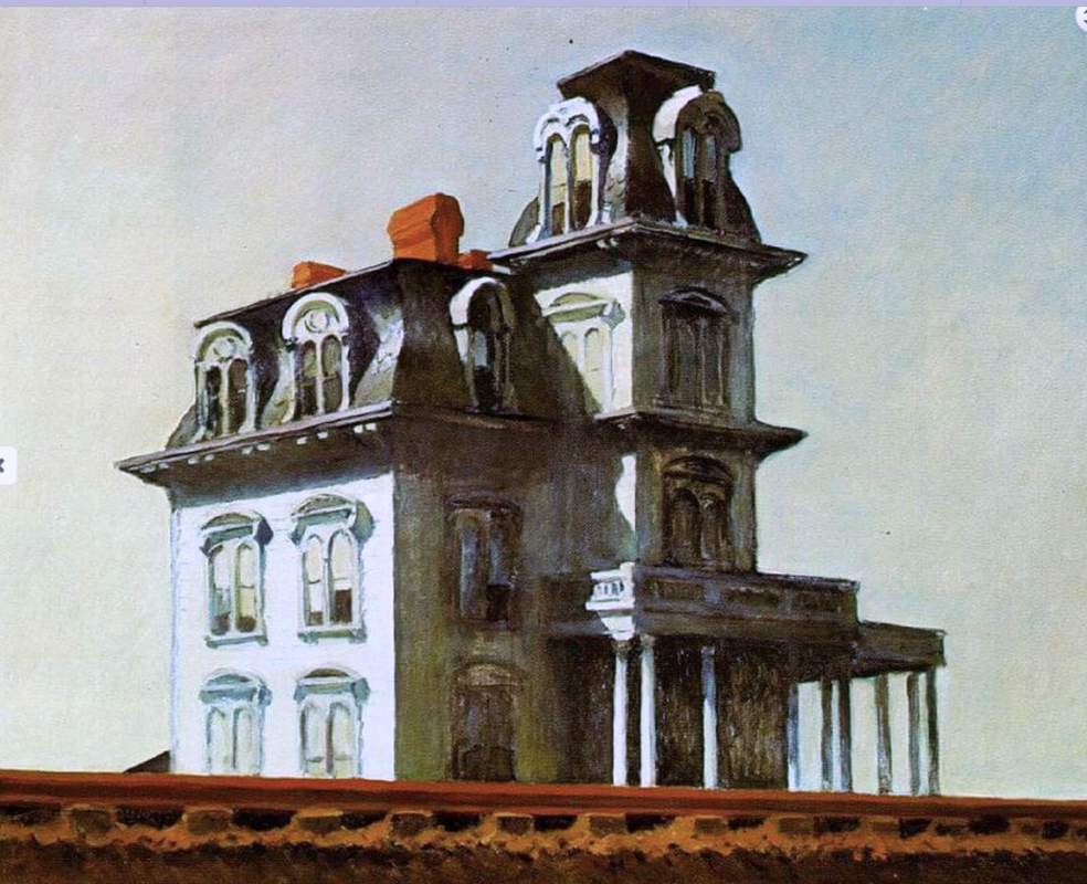
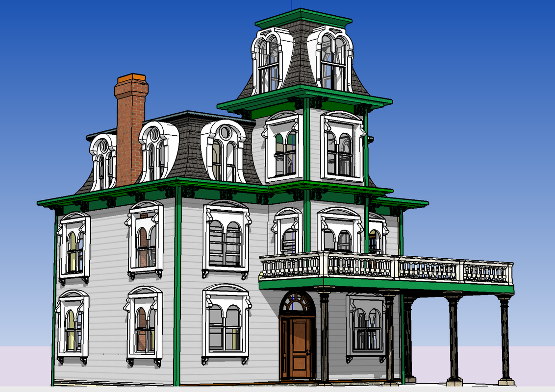
My next project is going to be for the model railroad and will be my rendition of Edward Hopper’s masterpiece, The House by the Railroad. I had to draw the entire building from his painting, imagining all kinds of details that were in the shadows. I have 3D printed over 100 architectural details and have had the flat parts laser cut by Rail Scale Models. It’s all in the shop waiting. This will be an interesting project that I’m anticipating writing an article about.
Here’s Hopper’s painting.
And here’s the SketchUp drawing that I made to produce the model.
If any of you wish to follow the construction of the this 1:48 scale model, I’ve been running a continuous thread on the O’Gauge Railroading Magazine Forum since April 2013. It’s now 84 pages long and covers an enormous amount of work. I will be posting daily construction notes on this project as I do with my plastic kits.
Page 1 starts here: https://ogrforum.ogaugerr.com/topic/continuing-saga-of-the-pandampprr?page=1
This project will start around page 84.
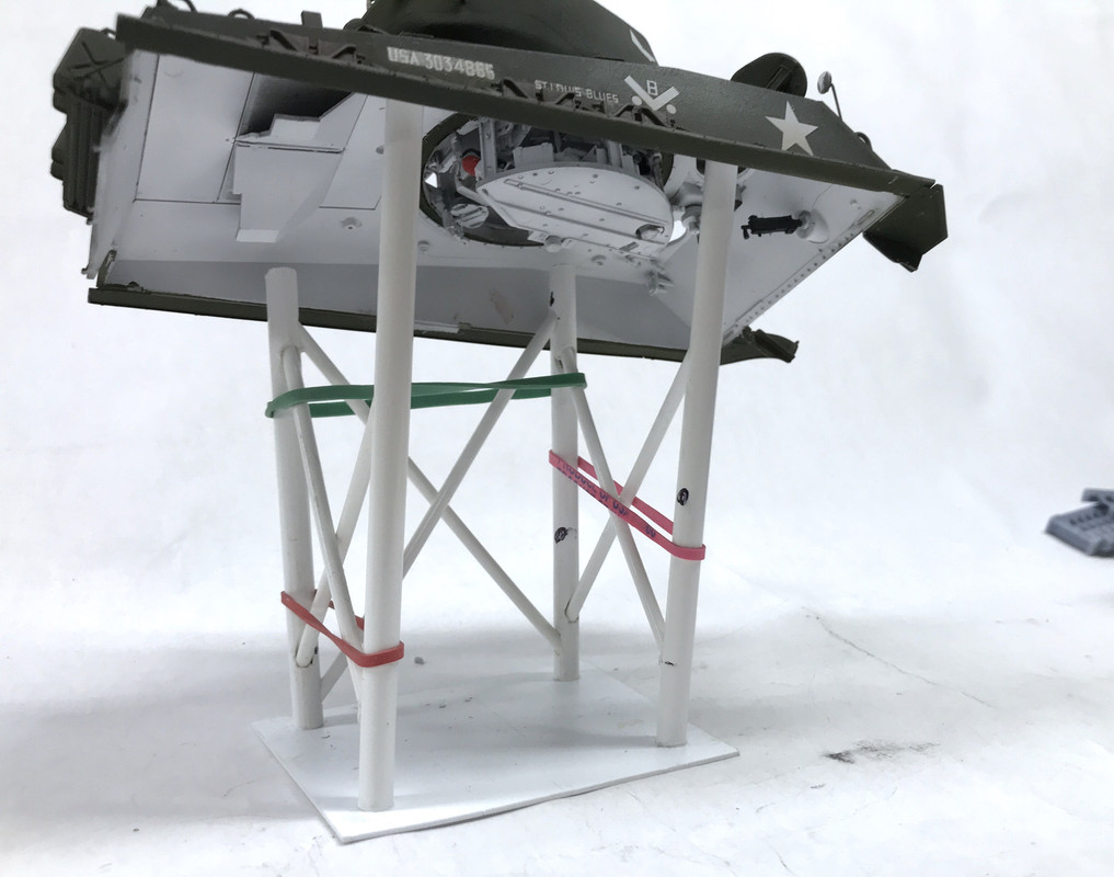
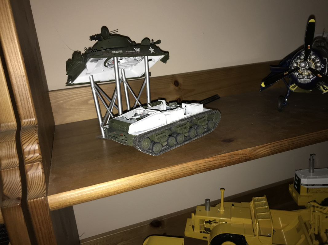
Did one more thing on the Sherman. I’m cobbling together some for of display rack to let people view the underneath. My attempts to 3D print something didn’t work, so I resorted to old school. I used two sizes of Plastruct tubing. It was a pain to drill and shape the openings in the uprights so the cross bracing would set at the right angle. I did not want butt joints. It isn’t very square since I should have made workng drawings to accurately measure the cross bracing. I will spray paint it some nice Tamiya Real Metal paint and that will be that. Instead of making a separate rack for the turret, I’ll let the turret display while attached to the upper hull.
And I’ve purchased the Bradley, so when the House by the Railroad is finished, it will be my next kit. A nice thing about this kit is sensible workable tracks. One part per link and they snap together so no glue anywhere. What a difference between that and the Ryefield 6 pieces five of which had to be glued without gluing the other two that had to be movable. The fact that the track mostly works is quite remarkable.
I will start a separate build thread in a month or so. Stay tuned!
I painted the stand and it’s now doing its job.
Fantastic job there!!! Looks amazing and I’d swear after this I have a better apprecation for the complexity of the real thing.
Love the stand and love the Hopper painting house- good luck with that!!!
Outstanding work! Thanks for always taking the time to share updates and photos on this build it was very interesting.
I’m sure the Hopper house will come out amazing. I’m looking forward to seeing a future topic on the Bradley.
Thanks. I anticipate the Bradley’s going to be more “fun” than the Sherman. The Hopper House is, indeed, going to be a neat structure.
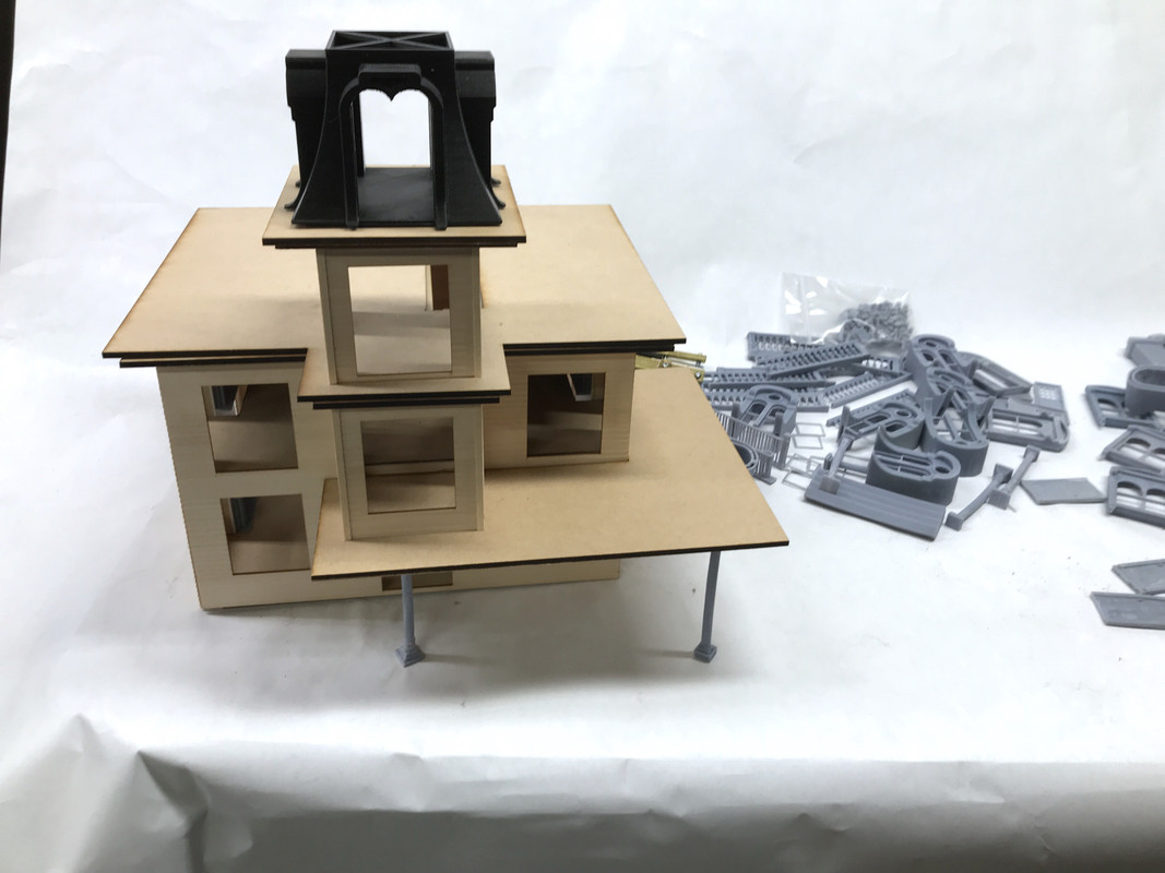
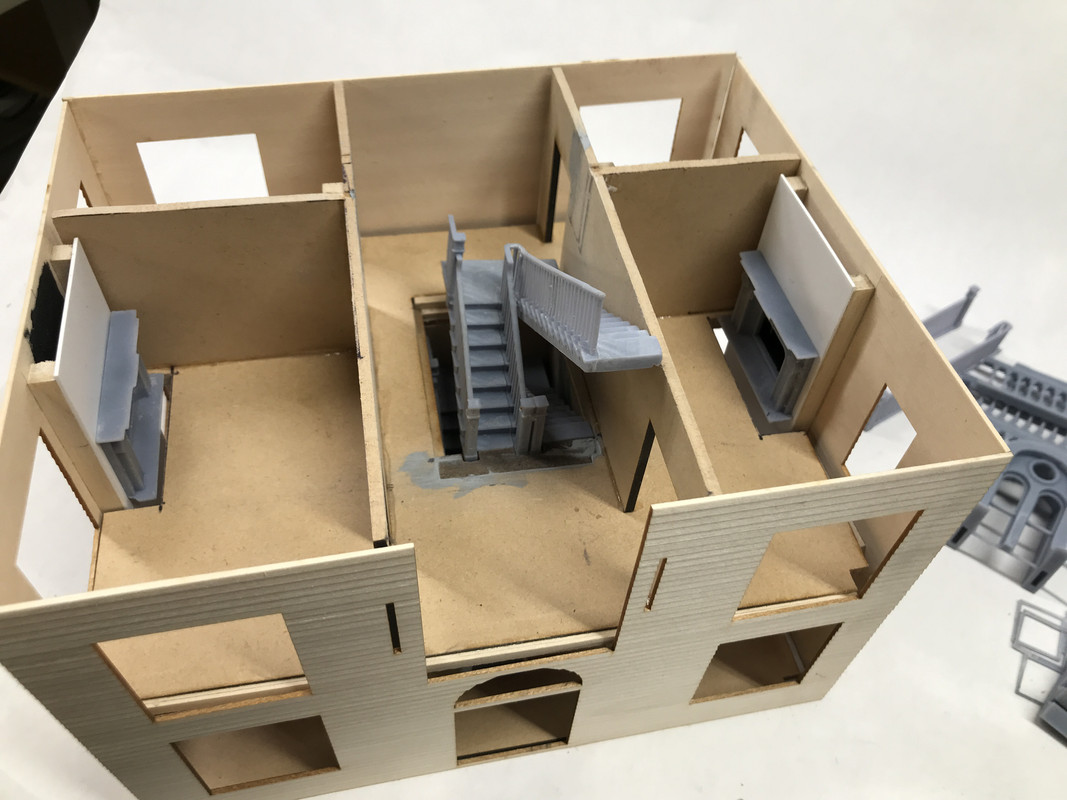
The stairway, while probably not very visible when embedded in the House, is a fun challange that I’m doing “just because I can”. This is the foyer and 1st floor with the to-be-detailed entry hall closet roughed in.
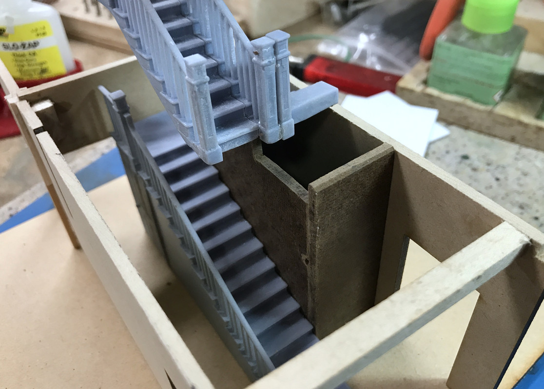
Here’s the second floor installation. The staircase is one unit comprised of 11, 3D printed parts all glued together with the same UV resin as it’s made of or CA. The four fireplaces were 3D printed too. In all, I printed about 100 parts for this.
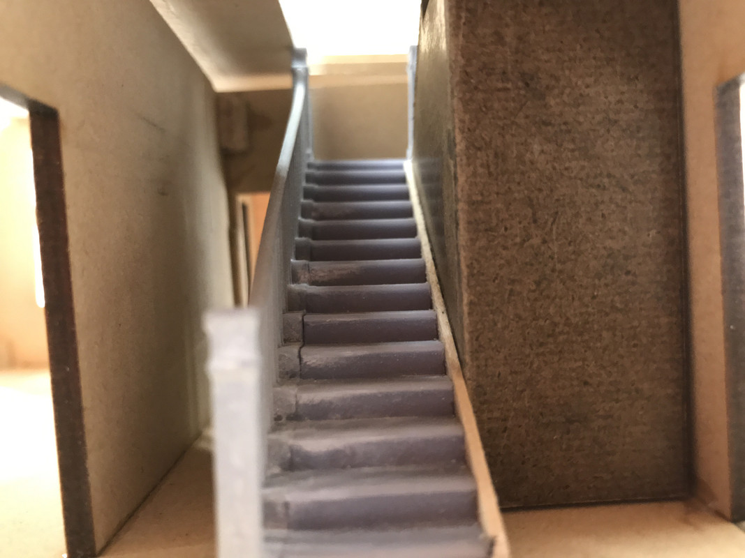
I took this fun shot looking in the front door. There’s a seam on the stair treads. I was unable to print the entire stair with railing without having supports in places that would have damaged the finished product in their removal. By separating the steps into the railing and tread areas, the print was doable. Unfortunately, getting a perfect seam was not. My iPhone 7 camera doesn’t allow you to change focal distances in small enough increments to use my photo stacking software. If I could, you can get closeup model shots that are in focus front to back. I don’t know if the new iPhone 12 will be able to do it. I’m getting ready for an upgrade.
I’ll periodically post status pictures of this project as I go along. It may not be plastic or a vehicle, but it is 1:48 and therefore falls into the definition of a fine scale model IMHO.