Great job there on the bogies.
Though I think I’d have given up on the working suspension and just cemented everything together. I mean once the model is attached to the base I’m never going to move the running gear again.
Great job there on the bogies.
Though I think I’d have given up on the working suspension and just cemented everything together. I mean once the model is attached to the base I’m never going to move the running gear again.
Thanks! I did break down and fuse one of them where the shock end wasn’t able to stay put. I’ll put that in as a center bogie.
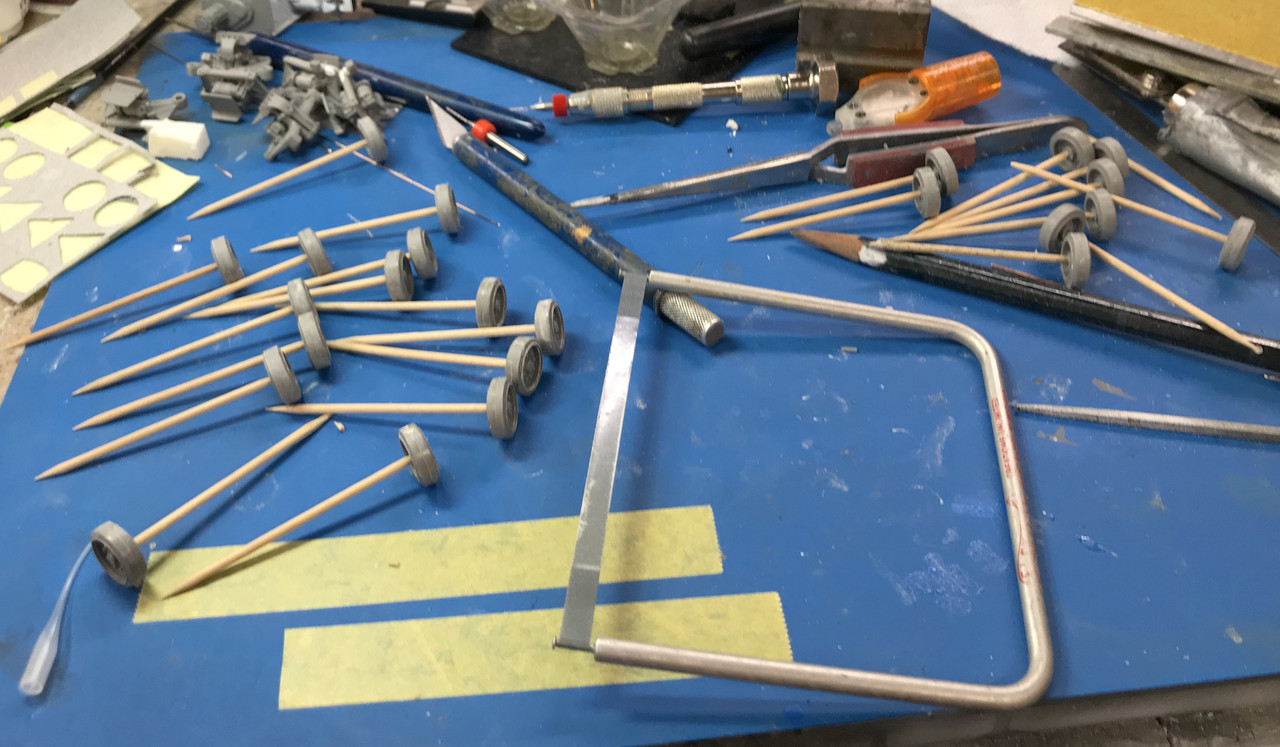
Short session: I had to prepare 24 road wheels by sanding off the sprue nubs and the parting line. I used this tool which I don’t remember what it’s called. It’s very helpful in sanding round surfaces since it conforms to the curve and prevents flatening the shape. It loads up pretty fast. At first I was just wetting it, and then turned on the ultrasonic cleaner and immersed it for a few seconds to remove the swarth.

Next I prepared the wheels for painting the tires. I had to snip the ends off the round toothpicks so they penetrated deep enough into the axle hole to firmly grip each wheel.
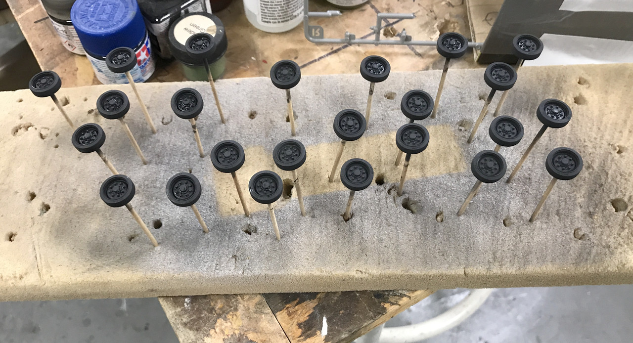
I airbrushed Tamiya Rubber Black. Used some IPA and a few drops of Tamiya Retarder so it would flow better and not dry in the airbrush. I stuck the painted wheels into a chunk of floral foam which makes a very good gripping surface.
While this was drying I started making the masks to paint the wheel hubs. Instead of painting the hubs first and masking to paint the tires, I chose to paint the tires and mask to paint the hubs. It was easier to make a secure mask for the tire. I first measured the diameter with the digital calipers, divided that number in half and re-set the calipers to the new dimension, and then set the dividers to that number. My first attempt came out a little small. I then guesstimated the center point of the hub and adjusted the calipers to the wheel rim. I then kept slightly adjusting until the calipers perfectly circumscribed the rim’s diameter. Tomorrow I will paint the hubs and the bogies, and then combine.

Rather than mess aorund with scaping paint off the bogies to prepare them to glue to the hull, I masked the bogie’s glue surface.

The bogies will be done tomorrow. After they’re installed it’s time for a tedious step: building the track from its 900 parts. There are 79 links per side (that’s like 5.5 parts per link). I don’t know how long this will take and it won’t create a lot of interesting pictures, but hey… it’s a tank and tracks, especially movable ones, are fundamental.
In cleaning the floor looking for another part, I found the headlight assembly. I didn’t even realize that it broke off. As I’ve been saying, Ryefield connecting points are very skimpy. I immediately drilled it for a pin and installed it with med. CA.

With that out of the way I spent the better part of an hour masking 24 road wheels 4 idler wheels parts and the glue area of the bogies. It’s always this way. Masking takes a lot of time and the air brushing is over in minutes.
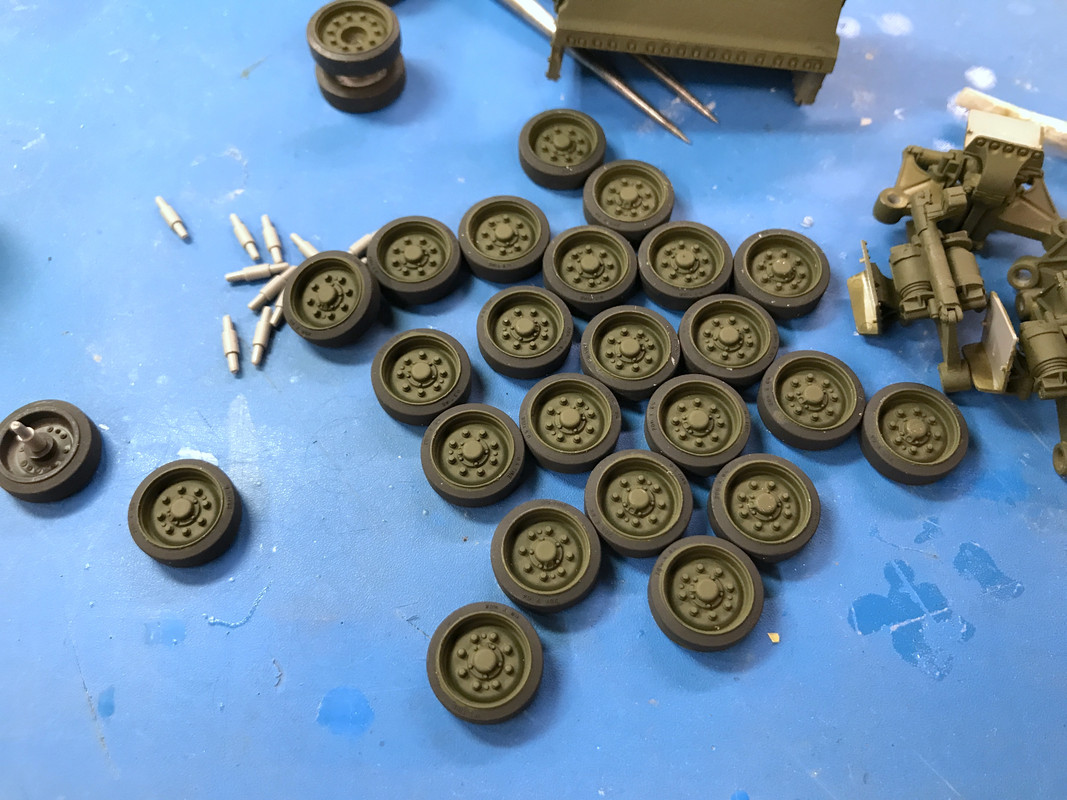
I used straight Tamiya Olive Drab for the first coat and then mixed a slightly lighter shade by adding some Tamiya Khaki to the O.D. This was air brushed also.
The first coat was Tamiya Rubber Black done yesterday. BTW: I sharpened on leg to a chisel edge on the dividers I use to cut the circular masks. This acts like a razor to cut the perfect circles. Periodically, I touch it up on a sharpening stone. You need to do this on a machinist dividers which have a screw adjustment. Otherwise it could easily change size during the operation.

There’s still some very minor touchup on the tires, but generally the road wheels came out very well.
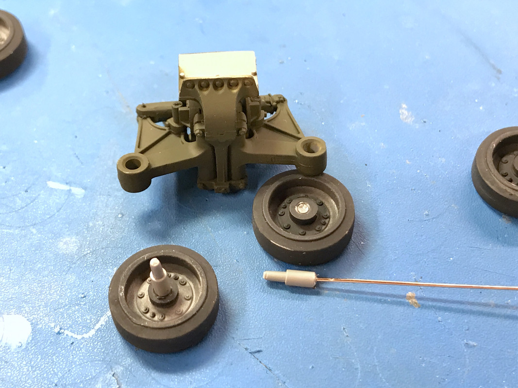
The idler wheels consisted of two halves and had a slightly larger diameter and hub so I needed to reset the dividers and cut those masks. They DID NOT have an alignment counterbore to keep the two halves in line when glung. I put them on a tooth pick to align them and added the liquid cement. I also used tooth picks for the bogies. The axle holes were just a little larger than the tooth picks so a couple of wraps with Tamiya Tape enlarged them so the parts were a nice tight slip fit.
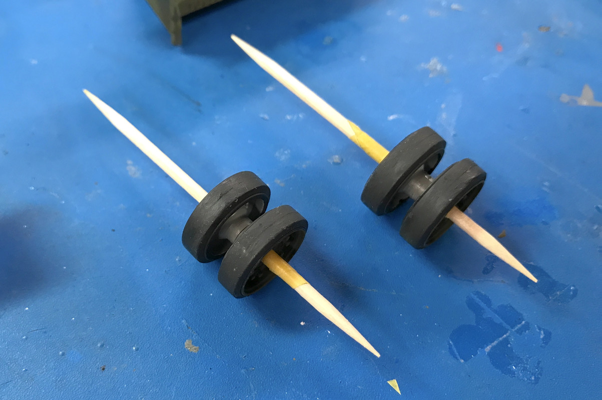
When the cement cured I slipped the idlers off the toothpicks.
To glue the road wheel axles you had to be careful to get the glue in the hole and not on the hub area. I put the axles in one side first, let it dry, then put them on the bench face down and placed the bogie over top, then I applied cement in the axle holes on the outer wheels and put the two together. I used my finest pointed Tamiya glue applicator to put the cement just in the hole. If any got on the outer surface I set that part aside and let it dry before re-gluing and installing.
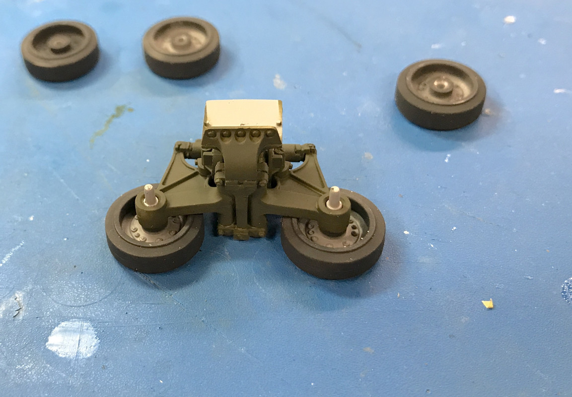
One of the axles broke without provocation. Really! I didn’t do anything to it. I think the glue weakened the styrene. I drilled and pinned it (not shown).
When all the bogies were assembled, I needed to paint the hull before installing. I had to entirely mask all the interior so I wouldn’t wreck all that previous work. Like the road wheels I pre-coated rubber black, then O.D. and finally the highlight O.D. Masking again took much longer than painting.

I installed them on the hull. I noticed that the bogie brackets that were to join the hulls didn’t form a perfect right angle. I don’t know whether the bracket was out of square or the gluing up of the hull sides since all of these were separate parts. This made gluing less than optimum. I used tube cement to better fill the voids. Even so, two of them let go and had to be re-glued. It mess up my paint on the bottom a bit. I will touch that up later.
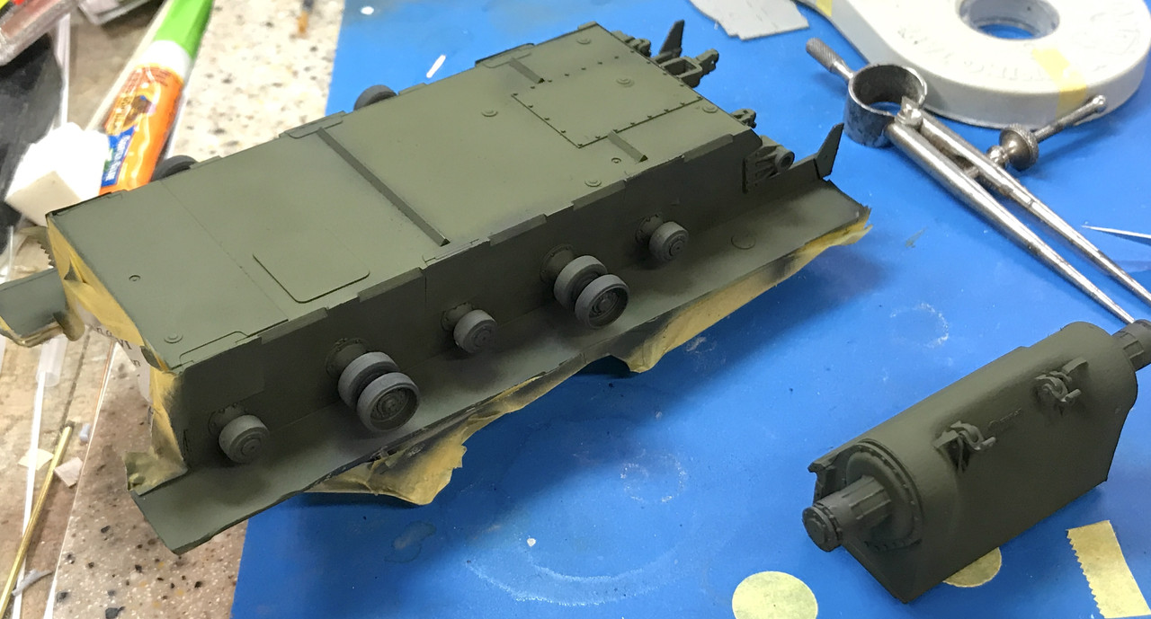
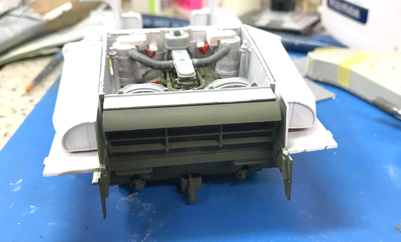
Here’s the bottom paint. I didn’t mask the return rollers. I was careful airbrushing so I didn’t coat all their tires with black and where I did, I will brush paint later.
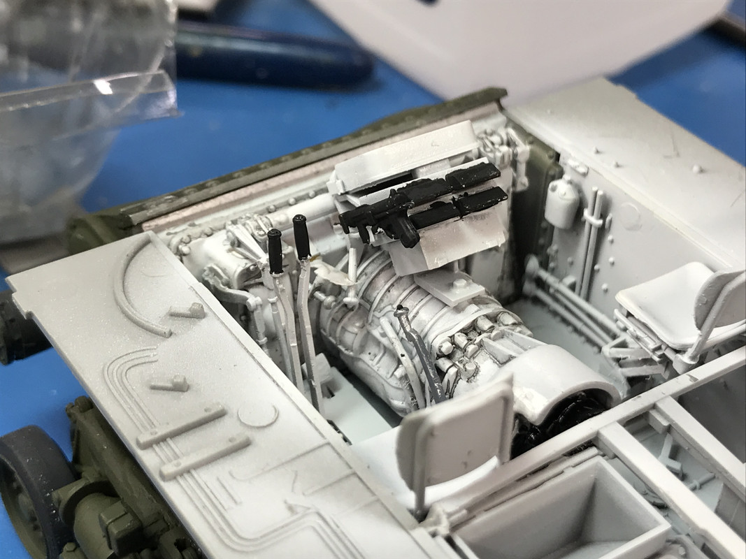
I gloss coated the trans assembly so I could effectively use Tamiya Panel Accent. I thinned the material with low-odor mineral spirits. The gloss prevents the accent from absorbing into the surface and gives more definition. The result was good. I painted the grease gun and the outlet vents. I then installed the trans assembly into the gear case and then the gear case to the hull. It’s a shoe horn fit and requires manipulation. You need to be careful so you don’t put stress on the rest of the very fragile hull assembly.
I picked out details on the control handles after gluing the control handle cranks to their respective locations. The tank now has steering. I stil have to paint the canteen and the 50 cal. tripod that’s hung on the right side. And I have to paint the seats!
I masked the tail so the radiator outer is O.D and the inner remains haze gray.
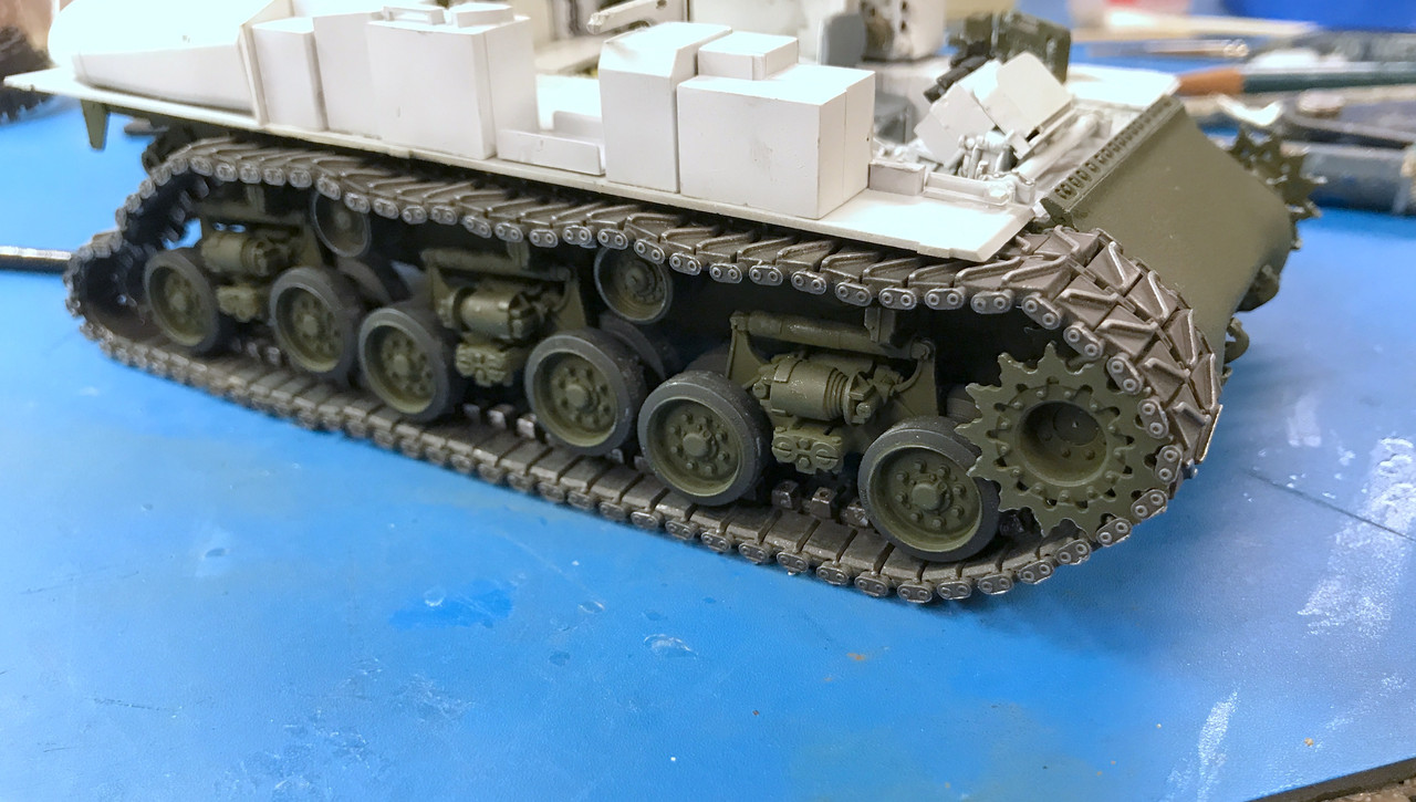
So here are all the boggies in place. All the wheels rotate and the bogies do articulate.
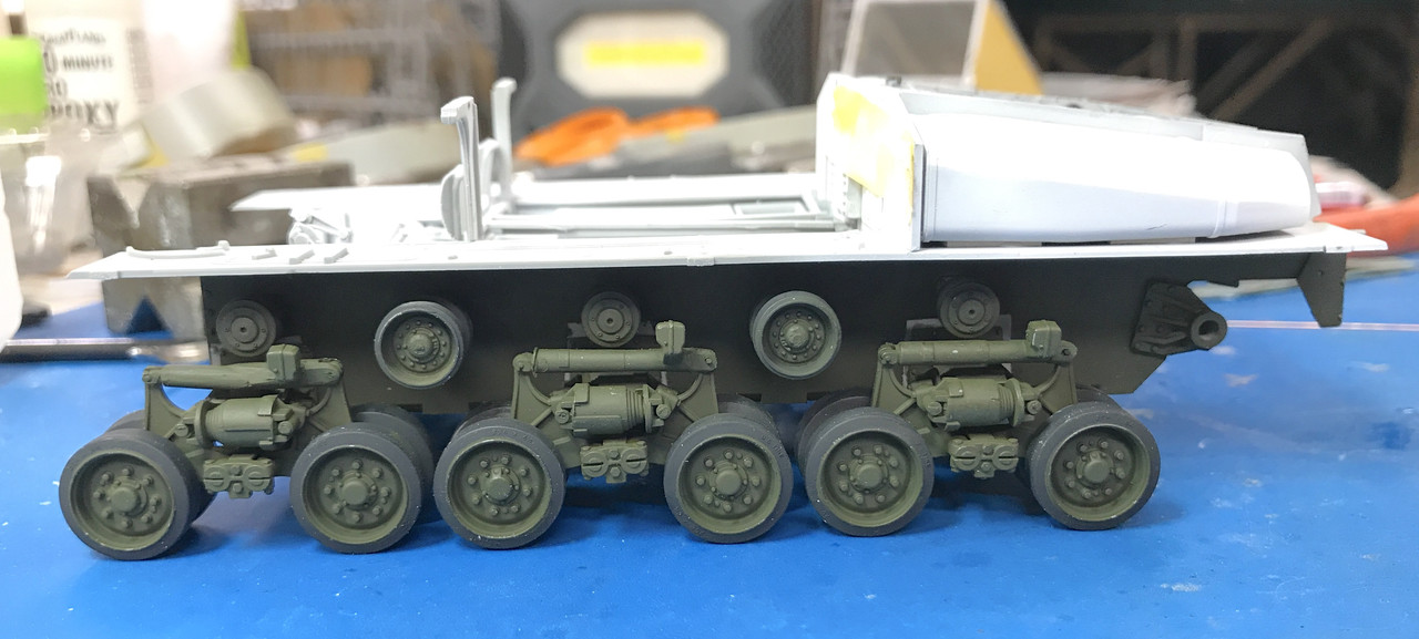
Now that the gear case in on, I can install the drive sprockets and start working on the tracks. I just noticed, by complete randomness, I have all the bogies with the jerry-rigged shocks on one side and all the factory ones on the other. This side is the fixed one. You have to spend some time staring at it to see it.
Oh wow, that’s a pile of work but your results look spectacular! [ht]
It sure is, and the track work commenced today and Whoa!.. It’s a real pile of work. The first six-piece section took over an hour, but there was a learning curve. I’ll walk you through it and explain.
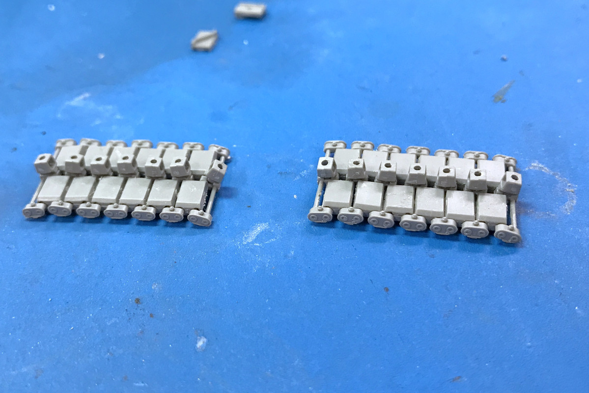
They give you an assembly jig of sorts that holds the individual track pads. Instead of simplifying it as maybe they could, they made the left and right track pads separate pieces, but made the pivot pins and end caps on piece. The track pads lay in the jig very loosely. So loosely that I was constantly knocking them out of kilter when attempting to place the next piece. The link pins are connected to a piece of sprue that holds them in alignment.
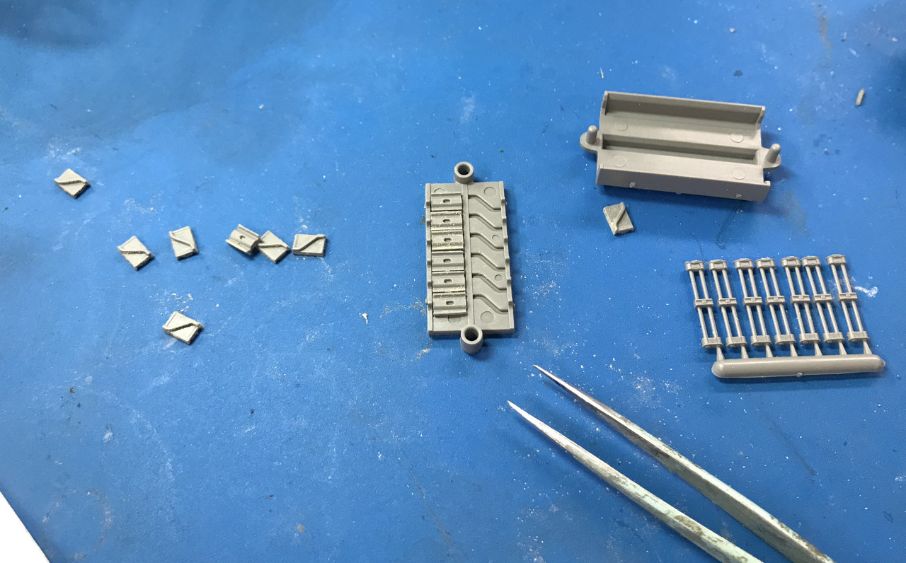
You see the little divot in the back of the track pads? That’s where the inner piece engages and captures the link pin part. You have to get cement ONLY on that little land if you want the track to move when built. That’s tricky! When I started to glue the first inner piece in place, I was unsure if they were gluing in place since the pads below were still moving all over the place, and the sprue alignment piece was tipping them out of the jig due to its weight. I wasn’t happy, so I cut off the alignment piece. BIG MISTAKE! The result was this.

The whole freaking thing went all over the place. Then things really went wrong! I started bebuilding it and then noticed that I had some of the links upside down. They not only have a right side up orientation. They also have a left-right orientation. I popped open the few glue joints that were completed and switched them around and glued all the rest of the inner pieces. The track moved. It was time to glue on the track alignment lugs in the middle. But where to they go? There didn’t seem to be any place to glue them.
That was because I screwed up again! I have oriented all the links upside down. The correct way presents a little square notch in the middle where the alignment lugs go. Luckily, the glue hadn’t cured hard yet. I was able to pry all the parts apart, reverse all the links and build it all for the third time. This excercise took almost an hour to build 6 links. There are 79 links needed per track. At that rate, I’d get the tracks done by Christmas… maybe.

Notice on the above that the pin ends have a dimple. This denotes the outside of the track. That means that after the first 79 links are make with one orientation, I have to have the presence of mind to reverse it for the next 79.
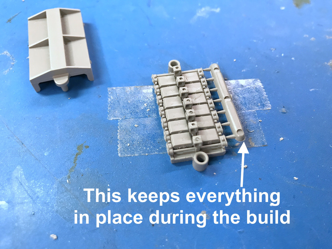
The second go around was much, much better. I had already solved one problem. The jig was also moving around. I fastened it down to the work surface with double-sided tape. I also did not remove the alignment sprue on the links. I also had confidence that I could glue the inner pieces carefully and still have flexibility. The second 6 links took about 10 minutes. That’s more like it.
So now I have two whole track units. The tracks units are combined with another set of outer and inner track pads, but without the benefit of the jig. The jig has a top half which is supposed to align the lugs before they dry. I suppose it works, but I’m not so sure. The track seemed to get stuck in the upper part and to remove put too much stress for my liking.
And if the assembly wasn’t tough enough, all those parts had to have their little sprue nubs removed. So far I only lost one inner track pad. If I was able to get my arms around this deal, I was prepared to buy an aftermarket set from Frulimodel or equivalent. So far, I sticking with it, now that I have it sort of figured out.
I got the seats painted and touched up any damage to yesterday’s painting session.
That gives me a headache just to look at it…
Asuka/Tasca’s Korean War M4 has a somewhat simular track design but not as complex. And it’s still a little too much for me. On a tank with tight tracks I’m happy with the ‘rubber band’ style.
The annoying thing is the prototype track was a single piece with the pins on both ends and the lock link on the ends. This is a much simpler way to build the tracks. The metal tracks are done this way. Instead, Ryefield uses five pieces per link. I can guarantee that some of those links are going to freeze due to some glue leakage. Hopefully none will fall on the curves. If murphy has his/her way, they most certainly will.
Very impressive work! The interior is coming along nicely and the OD on the outside of the hull looks really nice.
Those tracks look like a real headache to do. The Miniart workable T-51 tracks I built look simple in comparison to the Rye Field tracks.
Thank you!
There’s a silver lining… my local hobby shop, Scale Reproductions Inc. (one of the finest privately owned full-line hobby shops in the country) has a couple of separate Ryefield’s track kits for the Sherman. So if I continually lose parts, which I am wont to do, I will have a source of additional parts to finish them. And I’m getting the hang of building them. Need a couple of shots of Bourbon to steady the hands real nice.
One of the members of the very fine Military Modelers Club of Louisvile (MMCL) is the technical director of the University of Louisville’s Advanced Manufcaturing Institute. And he and I collaboratively designed a simple holder for my CA glue collection. I don’t know about you, but those tall skinny bottle don’t like to stand vertically. They’re constantly tipping over and are a pain in the butt. This holder provides a slot for each of my normal CA’s (Thin, Medium, and Thick) and the bottle of accelerator, which also is never where I want it.
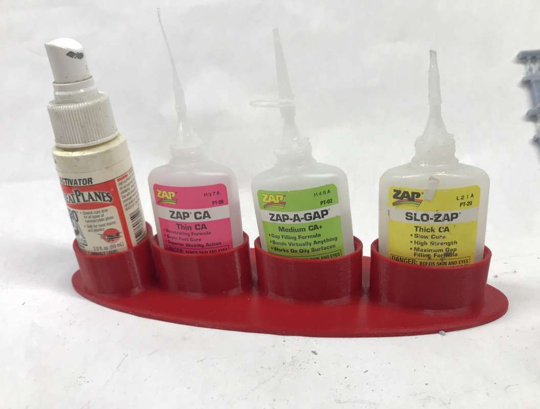
We had three variations. The first was a two tier design with some angled supports. He simplified that to this cup design. Of them one has a solid bottom and the other is opened up. I chose to use the open-bottom version since I anticipate the bottles gluing themselves into the hole due to material on the outside of the bottle.
This little rack will make my work easier. It’s all part of the ongoing “workplace optimizaton program” or WOP, that I’m undertaking to finally get my chaotic workspace under control. At the hobby shop yesterday I had my eye on the AFV Club Bradley Fighting Vehicle with TUSK armor and FULL INTERIOR. I’m really getting into this full-interior stuff. And my LHS owner can probably get the Ryefield Abrams with the full-interior. This will occur after I build this model and another major railroad project.
Hello Builder
Thank you very much for sharing your progress and the pros and cons on this build.
Have to admitt:
Bought the Typhoon before you started yours but you made me pick it up from the SOD.
Same with this build - My Dragon M4 is back on the table after +10 years in the twilight zone.
XLNT and most inspiring!
Keep them coming and late Good Wishes on your 75th!
Very Best Regards
Svenne
Builder2010, I enjoy watching you work through the incredible detail in this kit, but like Gamera said it would give me a headache if I attempted to build this kit. I think it’s safe to say this sets the bar at a new height for interior detail in a Sherman.
Harold
Thanks! Yes… I suppose it does. Today I really got down to business on making the tracks. First I completely cleaned and reorganized the work area. I had a pile of miscellaneous crap on the left side, and more at the back and on the right as well. It made it hard to find little bits when they launched. I also put up a cardboard wall on the right size as a backstop to “catch” hyper-velocity little parts. I put quotes around “catch” because it’s working more like a richochet board that reflects the projectiles to other unknown places. I hear them impact the cardboard, but then it’s anybody’s guess as to where they actually land.
I noticed in my picture of the lastest interior work that the angular support on the driver’s side was no longer there. I didn’t realize when it broke. I did find it on the floor. To repair it I reinforced the joint with a piece of 0.032" phos-bronze wire and some CA. The fracture zone was too small to just reglue it. Then all hell broke loose when I was working on the hull to fit that part. The front left bogie came off the tank! The little plastic part that glues to the bogie strut and the bogie then fell apart since this little piece is the key to keep it all together. To make matters worse, one of the pins that serves as the pivot point for the right swing arm was broken off in the swing arm.
It took almost an hour to repair it all. I had to drill and pin the right arm pivot and then drill and pin the retaining plate itself since its glue joint was getting too munged up to be effective. The shock pivot on the left side (one of the kit hinges) kept separating. Each time that happened the volute spring would fall out. This happened over and over. I finally glued the volute to its resting places. This stabilized the assembly. It reduce mobility, but at this point mobility was the least of my worries. I was beginning to doubt if I could get it back together at all. Once it was stable, I could get the pinning done, got it all back together and touch up painted.
Then I got back to the tracks. I’ve got it down to a more fluid thoughtful process. I found that pre-staging everything made it go much faster. In fact, the fine cleaning of all the little bits took much longer than the assembly.
I found that supporting the sprue that has all the pivot rods kept it more level and made it easier to glue the inner tread pads, although it was holding it a little elevated. I eventurally went back to just letting it lie there while gluing in the first couple of inner tread pads. Once a few were in place, it stabilized. In this image you can see that the pivots are sitting a little proud of the right side tread pads (on the bottom).

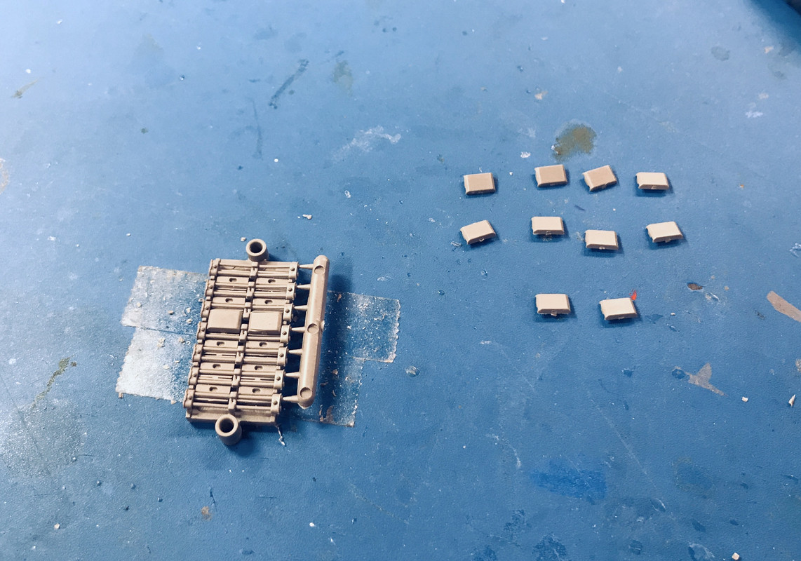
I found that staging the inner pads so they all face sideways I was able to grab them in the right spot with the tweezers and get them in position quickly. The amount of liquid cement I’m using is very litte and it evaporates very quickly. If I fumble with the parts, but the time I get them in place there’s not enough to hold the part. You have to be quick and precise. Often those two things are mutually exclusive.
Here’s the caps lined up ready to glue in place. Remember: the glue can ONLY go on that little ridge with the open divot in it. If it runs down the side of the ridge it will get into the pivots and freeze the tread at that link.
I took another one of the jigs (there are four, one for each of the tread sprues) and removed the end lugs. Those lugs line up the upper part of the jig. This let me use it as an alignment jig for joining the 6-link track segments.

Joining the segments is easy with this method. I ended up fastening the jig to the table with double-sided tape so it wouldn’t move around. You have to make sure you’re fastening each segment in the proper orientation to the rest of the track.
I’ve completed 44 links so far. Each track requires 79 links. So I’m halfway to the first track. I think I’ll be done the tracks by next Friday. They are getting faster. I did four this afternoon and that included fixing the that pesky bogie. The track is nicely flexible, but it’s not very strong. In fact, I really wouldn’t want to put any stress on it. I’ve already had some links break loose when the inner pad glue joint wasn’t secure.

Everyone have a nice, safe weekend. See y’all on Monday.
Those tracks are coming out really nice. I can see how those tracks would be fragile once completed. I don’t envy you putting those on the model once completed.
You ain’t seen nothing yet. I finished track one today and started track 2. Several things occurred. I found one tread that was somehow reversed. I attempted, briefly, to break it and replace the shoes correctly, but quickly realized that I’m make that errant tread is not easily seen.

Next, I produced all the links needed for track one. It needs 76 links.
Unfortunately, I overcounted by 7 links. So I made the track with the correct number. Then there’s this: The instructions clearly show you create a full loop and lock it in place by adding the idler roller to pull the track in place AND use the eccentric to tighten the track properly, much like the real one.

Unfortunately, THIS DOESN’T WORK! The track won’t fit over the return rollers. You can’t get the darn thing in! You will break this fragile track if you try and force it. The only way to get the track on is to have it NOT CONNECTED. This is troublesome becasue of how tricky it is to install the top and bottom tread halves even when they’re in the jig. Doing so when the tread is on the tank will not be fun.
Lastly, those 7 extra links can’t be used on track 2 because they are backwards. The track is to be installed with the simulated hollow connector pins facing outwards, and the tread pattern needs to be consistent of both sides. I thought about breaking all the glue joints and reversing the treads, but quickly found out that the glue joints only let go when you don’t want them to. If you want them to, you have to destroy the parts in the process.

I’ve gotten much faster building the track. I think I did 6 or 7 sets today. And I’m going to change my plan to not assembly any of the track to avoid the miscount from the first track. I’m going to produce the series of 6 links and when I get close to 76, I know exacly where I’m am. It’s easier to count by 6s, than individual links.
Oh gee friggin’ whiz… [bnghead]
Good luck with getting the tracks on there, I have no idea what to do. Looking forward to seeing how you solve this…
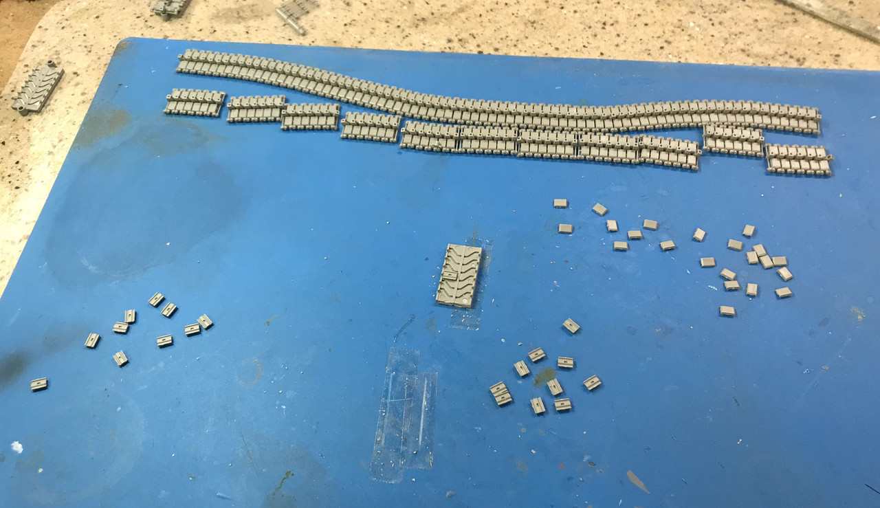
Believe or not, the tracks are finished and two days before I said they would. I really did get into a groove and perfected all the little actions that streamlined the process. By not connecting the sub-groups until the end served two purposes: it gave them a chance to fully set before messing with them, and it was easy to count the number needed to complete. As it were, there were enough extra parts to complete both tracks AND have some pieces left over including all the pieces I lost and that extra chunk that I couldn’t use. I believe the track is actually sized for the Jumbo Sherman which was a longer vehicle than this version. It worked out that 10 sets made the length. Even though 10 X 6 is only 66, there is one additional link between each set, so the total is actually 76.
In this image, all the segments are complete and I’ve cut and cleaned the tread parts needed to join the 10, 6-link sections which include the pins and center guides for the connnecting tread pieces, equalling. I cut 10 left and right outer treads and 20 inner treads. I actually only needed nine. The 10th will be used to loop the tracks.
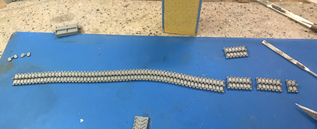
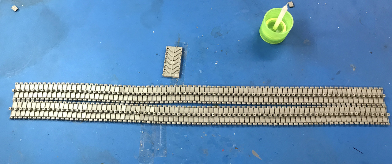
So here are both tracks at 76 links per. Since there’s one more link that joins them, it’s actually 77. The instructions said make the length 76 links. I hope that they were talking about the track in the flat. Otherwise, I’ll have to add two links. I have materials to do this. I bought the track kit, but thankfully don’t need it. It was $20.00 and that’s a lot of dough to spend if I only needed a handful of parts. It was a provisional buy and I’m glad I did it.
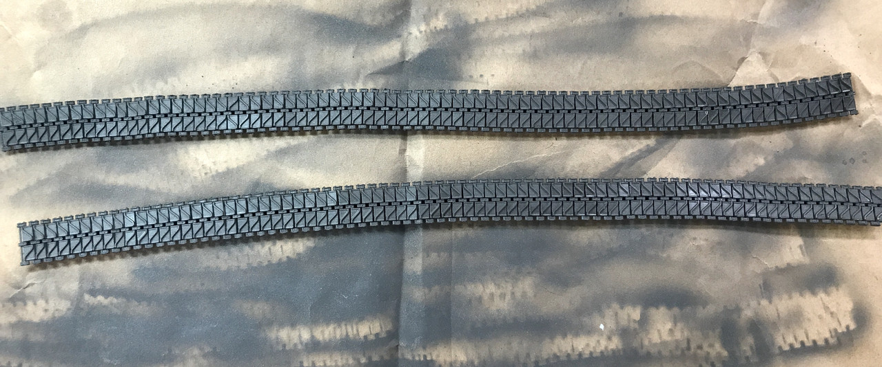
For the base coat, I airbrushed the track Tamiya Dark Iron. It’s a very slightly metallic color and looks like a deep brown rust. I will add some more color in further operations. When this totally dry, I’m going to Dullcoat it to serve as a barrier for further treatment.
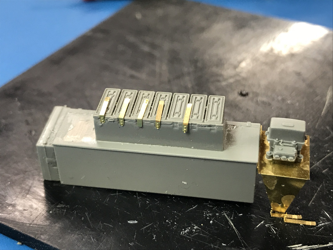
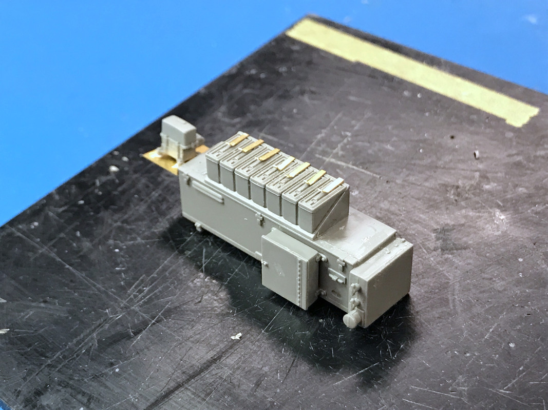
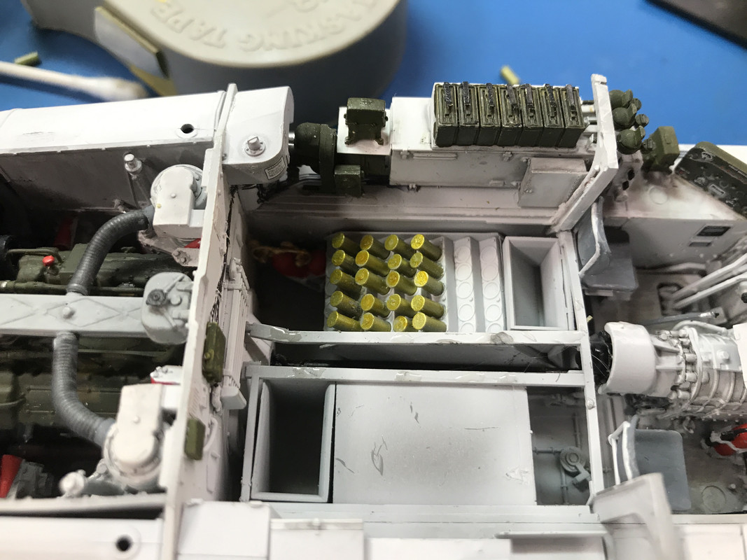
While this was drying I got to work on the next steps: assembling more details for the top of the sponsons. The tank has all kinds of storage compartments. One, which you can see, has three jerry cans for fuel. This is all for the right side except for that odd-looking thing that goes on the bulkhead in front of the left fuel tank. These get painted which initially and have some decals.

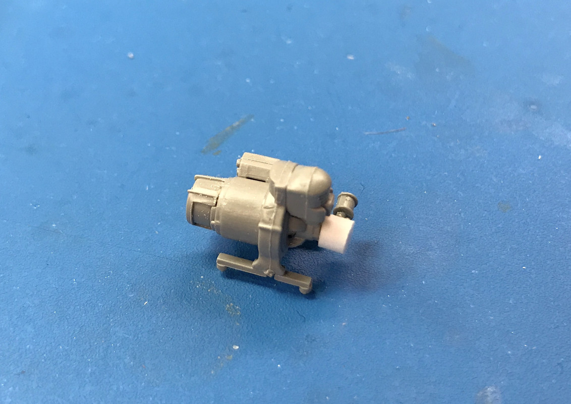
I also built the auxiliary power unit. There was a part that went on the front that got into the Rift so I faked it with a piece of styrene. This get’s painted O.D.
Tomorrow is an exercise day so I’ll have a shortened session. I will continue work on the tracks and then back to the interior details. I’m thinking of actually cutting away part of the turret to show the interior. I’m still thinking…
Whew, that’s a relief to hear the tracks went that well.
I like the idea of doing a cut-away. Not sure how I’d do it, looking forward to seeing what you come up with.
I won’t have to cut away the hull since when the lid is off it’s completely open. It’s the turret that needs to be exposed. The turret has a top and bottom half. It also has interior walls. If I glue the two halves together including all those internal walls, I can then cut through both. There will be a gap between the inside and outside wall that should be filled to simulate the thickness of the turret armor. I would probably make the cut from the loaders side since there’s more stuff on the walls on the commander side that would be sacrificed to make the opening. The other choice would be to just use the upper and lower parts separate, but you have to look up inside the upper half to see all the cool stuff and you’d be looking at the gun from the bottom, not the side.
All I got done on the tracks today was the Dullcoat layer, but I did do some stuff. I painted all those compartments that I glued together yesterday and built some more. I painted and installed the fire extinguisher that sits in front of the asst. driver. I applied some neat little decals and decaled the instrument panel. I also did some finicky little PE…is all PE finicky and little…just say’n.
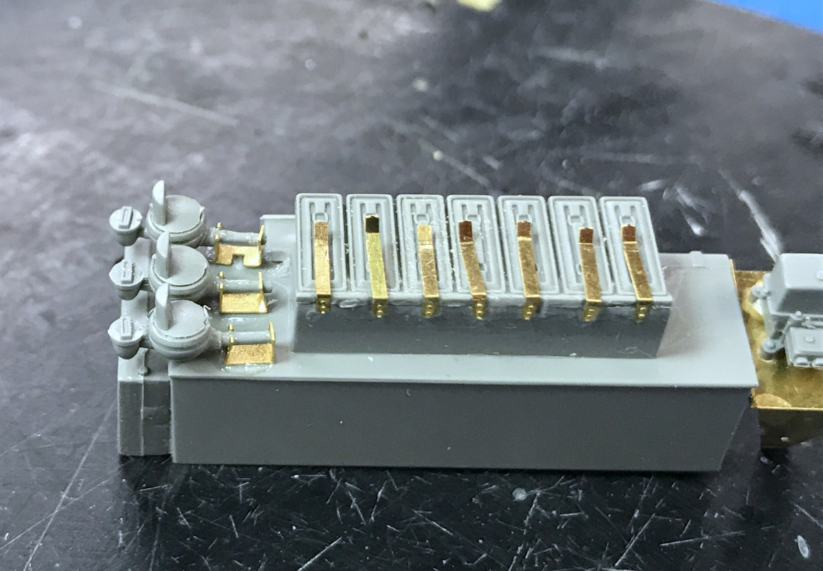
There is one particularly complext compartment that has all kinds of stuff going on. It has a rack with what looks like machine gun ammo boxes. These boxes are a two-piece molding, but the spring clips that keep them in place when the tank is bouncing around are PE! There are 7 of them. They are folded 90° and glue to the back of the upper box. Again, those are really fine-pointed tweezers in that picture.

I used thick CA for gluing PE. I’ve discussed this before so I won’t waste time here. To put these pieces on, I first positioned the part next to where it will finally reside, add a dot of CA and then slide the PE sideways until it seats properly. I went back over them with some thin CA to further secure these delicate pieces.
After gluing them in place I put a razor blade across of them and bent the forward lip up as it would be if it is a spring clamp. Notice also the folded PE shelf holding up that electrical looking device at the back.
If this wasn’t enough there is more PE. This unit also holds PE brackets that support replacement black out headlamps. The lamps on the tank’s front are clear lenses. The black out lenses were also carried on board. These and that relay device are painted O.D. along with all those ammo boxes.
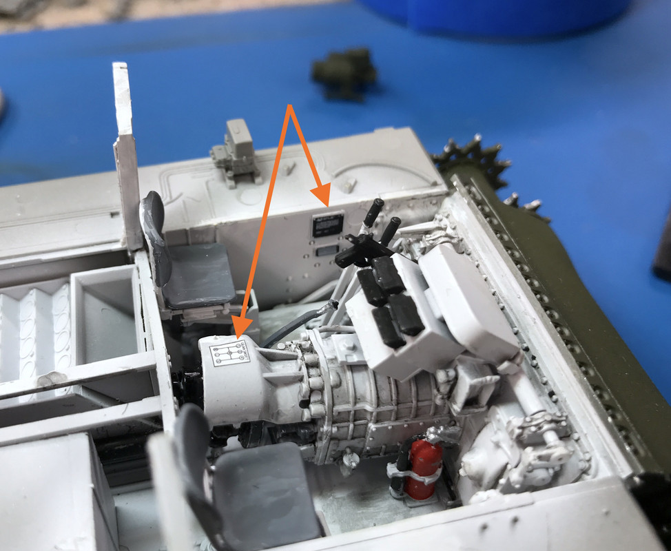
Here are those cute little interior decals. I can drive this beast since the shift pattern is now clearly displayed on the generator shield. The others are name plate decals. You can see the fire extinguisher too. There’s another relay device on the sponson that also gets painted O.D. which is why it’s not white.
Lastly here’s the instrument panel. Almost screwed this up just before I was quitting for the day. I decided to add another coat of MicroSol. And of course my brush caught a edge and turned the end under. I was able to pick it out sort of. This image was taken before that happened. I had gloss coated the panel before decaling. I will add some Bondic gloss to the guage faces. The kit’s decals seem to be pretty good. They’re not too thick and came off the backing quickly. More than I can say for the decals in the Airfix Typhoon. Those took 3 minutes or longer to break loose of the backing.

I think I may be able to get the tracks onto the return rollers without removing any guide lugs. I did a little experiment and think I can flex the sponsor lip just enough to get the track to go over the front roller. We’ll see. Track and other detail work tomorrow.
Oh that sounds cool!
And again, great work there with the interior details.
Thanks! Today was a milestone day. The hull is done and I WAS able to get the tracks over the return rollers by flexing the sponson just enough to get it in. There really was no choice. There is not enough working room when the track is installed to connect it together using the complex arrangement it requires.
Before the floor pan could go in I had to install the ammo into the wet magazine. Because this was already painted, the gluing was more troublesome than it should be. For the brass color I airbrushed flat aluminum yesterday and overcoated it with Tamiya clear yellow today. It does a good job simulating metal to do it this way.
While most of them are just stub ends, the middle rows are full projectiles which they give you elaborate painting instructions and decals, and then you bury them into the magazine and never see all that work, so I didn’t do it. You can see that I picked out the details needing O.D. painting. I painted those PE spring clips semi-gloss black just so they’d look different. I have no idea what color they really were.
I airbrushed the floor plan white and then went to pick out the panel lines. I did this after gluing the open hatches that would expose the magazine. I made a mistake of putting on the diluted panel accent (diluted with low-odor mineral spirits) which I thought would not dissolve the white since it’s solvent-based. It did not, but the flat paint absorbs and spreads the accent where you don’t want it. I removed it and then gloss coated the whole deal and went back and did the accent again. Then I hand brushed Tamiya clear flat to dull it done, but it was still too glossy so I shot it with Dullcoat. With the addition of the floor, the hull IS DONE!. This shows all the stuff on the right side.

And here’s the view of the left side. I repainted the forward left section since there were some little parts that I didn’t paint while, the first box of storage units looked terrible and the sponson itself was almost unpainted. I just masked around the area and kept the airbrush at a narrow stream. I have two airbrushes. I have my veteran (40 years old) Badger 150 which Badger reconditioned for free several years ago. And a fine line Badger 250 top feed for detail work. I seem to have lost the shift pattern decal… hmmm. I guess I won’t be able to drive it now since I don’t know where its gears are.

I had recently received the Kalmbach Armor Detailing book and learned that you can use pencil lead to create a worn surface for the inside running surface that contacts all the wheels. I first used A-K Interactive Real Metal paste to produce worn metallic surfaces on the center guides and the connecting links that make contact with the sprocket teeth. This is a wax-based paste that doesn’t dissolve the paint beneath and can be polished. If you’re familiar with Rub-n-Buff, this is very similar. It took a few minutes to apply the pencil. I then flipped the track over and added a bunch of brown weathering powder. I’m not sure just what effect it gave… I then highligted the grouser teeth with the same A-K product. I used a makeup sponge to just catch the tops of the tread. I like this effect a lot.
Here’s one view.

An another;

I then fastened the ends together using pre-painted tread parts. This went well since I have literally hundreds of trials learning how to do it. I was able to carefully apply pressure to the sponsor just enough so the track passed the double return rollers and it was installed. I placed the idler wheels in the track, but ran out of time before putting in the idler shaft and the eccentric adjustment part to properly tension the track. That will wait for Monday.
Here’s a nice front-end shot. This tank is mildly weathered so the track seems right to me. I’m not putting this on a diorama, but I may get some crew figures. I made some custom decals for a friend and he’s getting MiniArt and Tamiya US WW2 tank crews for me.

The tracks are perfectly flexible and miraculously, the tank can actually move. We’ll see how this works when the idler is on and there’s more tension. So far so good.
Once the idler is on, I two paths to travel. I have to finish the exterior hull with the painting and adding some more details. And then there’s the highly complex turret. I’ve looked at it regarding cutaway ideas, but still not sure how this will work.