We make our mold masters on the STL machines including gates, runners, vents and parting planes. When it comes out we just clean it up and pour the RTV A & B Sides.
OK, you caught my interest.[swg] Since I’m from Texas, and work at LM in Ft. Worth, and am assigned to the JSF Weapons team. Who did you do the model for?
FIRST QUESTION, NOT SURE I CAN BUT if I can get CAD Weapon files (Unclassified and ITAR Releasable) (probably outer mold line) can you scale them and produce some small models about the size of a tie-tack. And, maybe smaller so that I could put them on the side shank of a ring with a JSF on the top. Visualize a class ring.
You would of course be rewarded with a silver replica of each as my expression of eternal gratitude. And do it without getting anyone in trouble?
SECOND QUESTION, did you do the chess set? If yes, how did you get the CAD images, if I know that, maybe I can find some small cowboys and indians to do an experiment with?
Regards RLW
A large areospace company.
I can find the cad just tell me what weapon you want and what the final Size you need is.
Yes I did the chess set. I may be able to laser scan some cowbyus and indians and get the mesh files that way.
-
Each of the following 2cm in length
-
Each of the following 1.25cm in length but only 1/2 (flat on one side) on the Longitude such that it has a flat back and can be mounted on a ring shank
AIM-132
AIM-120
JDAM / GBU-31
GAU12
On the Cowboys and Indians, I have some ideas and more to follow.
Regards RLW
BTW if this is getting boring to the rest of the crowd, we can move this off line.
Ill get looking today. Should have the models done by monday PM me a ship to address.
Nope, not bored at all. Just saw what was happening. WOW! you two are good.
Sorry DK, I missed that you posted some of your work too. It’s great.
As for some of the rest, modelers do use RTV silicone rubber molds a lot. They are easily accessible and resin (two part liquid plastic)is the easiest medium for us to cast in. Even with the low temp alloys, “white metal” (I use the term loosely) is not feasible for most due to the handling requirements and the specialized equipment. Loss of detail is a concern too.
I do my own molds and casting. Very crude (compared to yours) as I need a degassing chamber to improve the finished quality of the castings. Trying to get any fine detail is near impossible. I know multipart molds are used daily, but have never figured out how to do them. Any help there would be HUGELY appreciated.
Thanks guys for the very informative and provocative info thus far.
Drew
Flattery will get you everywhere!
The molds that I describe below do use a vaccum chamber to remove air and increase the density of the resulting molds. I’ve tried cheap vac pumps but it really does take a good one. E-bay often has them for .25 on the 1.00 if your inclined to do it that way. ALL of my casting equipment was purchased used
Let’s try to remove the mystery of that. Following are TWO DIFFERENT APPROACHES TO A SIMILAR PROBLEM
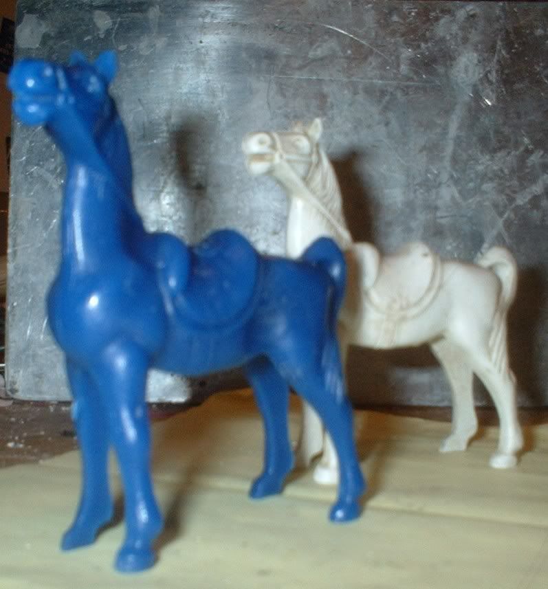
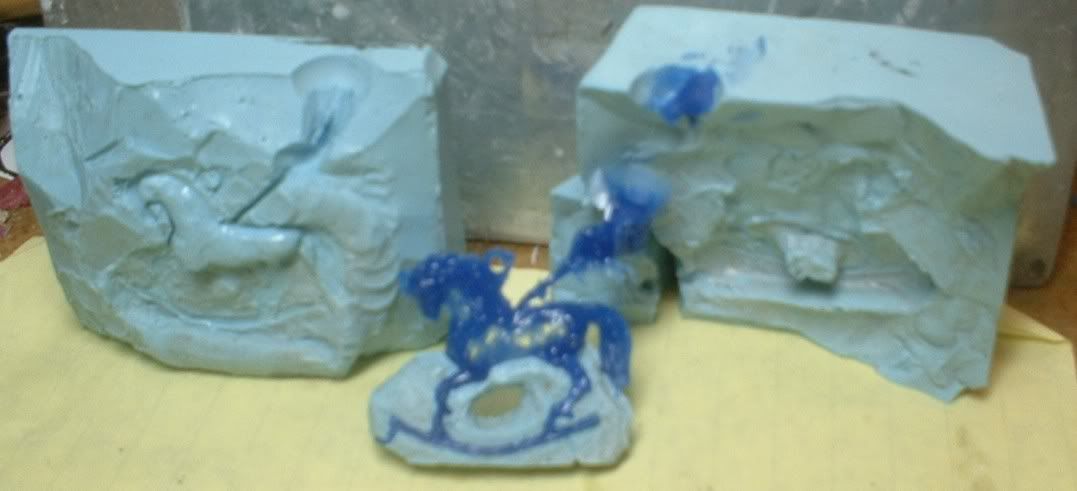
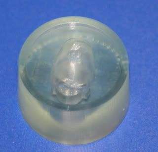
FIRST APPROACH NEXT THREE PICTURES – The RTV used in this mold is Castaldo Liqua-Cast 2 part 10 to 1 mix. I really like it a lot and the cost is very inexpensive compared to others I’ve used. It allows for better carving that the normal RTV two part blue. The first picture is of the Master (White) and the end result of the mold, a wax to be used in Lost Wax Casting (Blue). I’m sure that many of you have run into the problem illustrated, there is no single parting line that will suffice to get the part out once the material has been poured in, regardless if it’s resin, or wax, or Low Melt Alloy
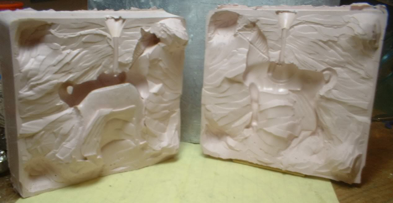
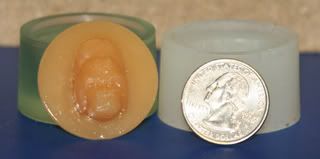
This next picture shows the first cut of the mold. BTW I do both carved molds as well as multi-part pours as in the second example. The objective is to be able to separate along a parting line that will cleanly separate some portion of the master while leaving the balance embedded in the other part. In this case the initial first cut exposed one half of the body and two of the four legs. The remaining legs are embedded in the other half (Left)
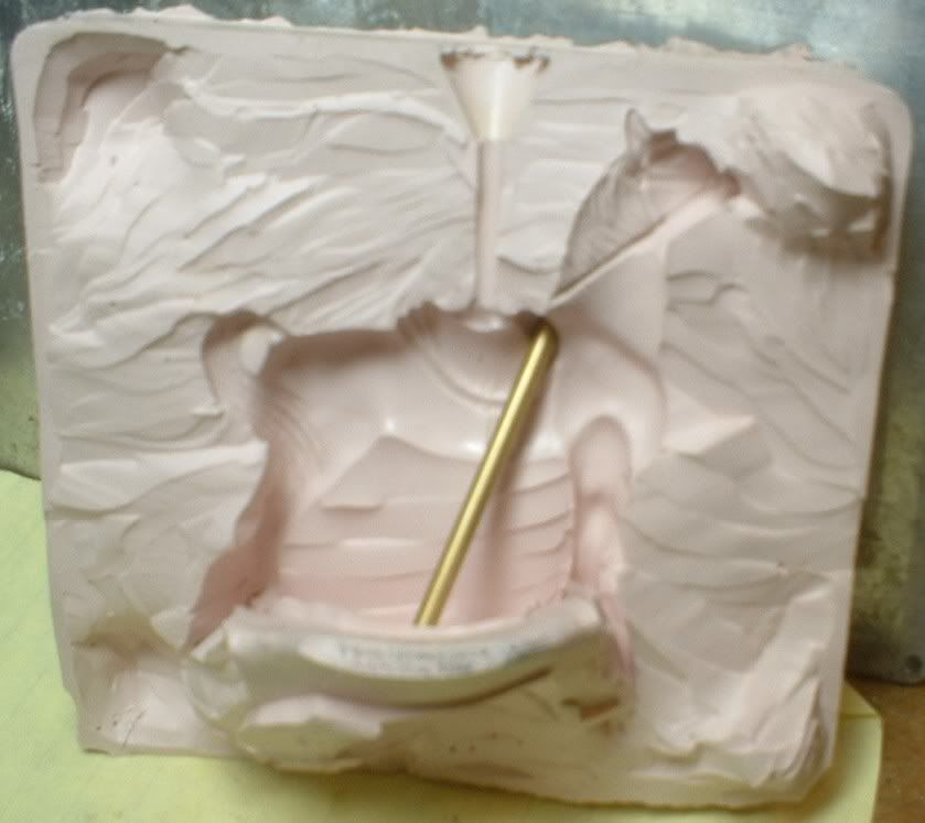
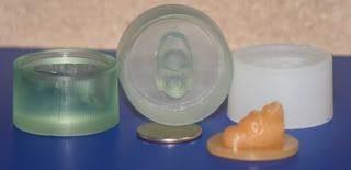
The third photo shows the cut that will allow the part to be removed. I had to prop it open with a sprue rod (1/8 inch brass). The trick is think where the cuts will have to be in 3d. The other trick is to orient the mold and know where the object is inside. I usually put a yellow sticky on the inside of the mold prior to pouring in the RTV with a drawing on the sticky facing out. Then I know where I can safely cut to get to the model. I have even taken pictures of objects sitting in the mold prior to the pour. As you do these cuts, you need to be aware of how it will fit together when you are ready to pour or in my case inject. You don’t want to have square or straight cuts that can slip. You need to leave enough mass to act as the hinge.
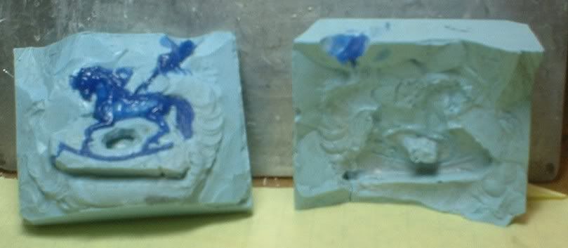
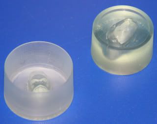
SECOND APPROACH NEXT TWO PICTURES – The RTV used in this mold is a no-name 2 part equal parts mix. I like it for different reasons, it is easier to work with when creating molds by a barrier separation method and is easier to work with when there are undercuts because it is soft and flex. The cost is more expensive. It doe not allow for carving since it is too soft and it will tend to break when bent compared to the pink.
The parting line determination method is the same as previous, you simply have to see in 3d and visualize how you want to achieve separation. In the construction of this mold:
- I took the master, a sterling silver pendant and put tape around the rocker portion thus creating the insert part.
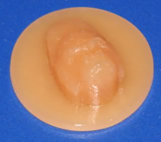
- I mixed and vaccumed the RTV
- Poured it into the pony sitting upside down, thus creating the mold that would be the space between the rockers.
- I then vaccum again with the pony in the chamber upside down
- Set aside to cure.
- Next I carved out the locating shape in the center of the rockers thus insuring that I could get solid and consistent position of the removable part.
- I then embedded the pony, with the insert in place, up to the desired parting line. The left picture would represent the clay and the right picture will be the second pour.
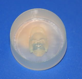
- After embedding in the clay, paint your parting agent on the inside of the box edges, on the clay, and very important on the first pour of the RTV. This is so the second pour which you about to do will not adhere to the part between the rockers.
- Mix, vaccum, pour, vaccum and set aside to cure. When step 9 is complete you will have mold part number 2 with a post that now fits into the hole previously carved.
- Remove all clay and put it back into the mold box with the two parts assembled and in a fashion that will allow you to pour the third and final part
- Paint your parting agent on the inside of the box edges, and very important on the first two pours of the RTV. This is so the third pour which you about to do will not adhere to the assembled first two parts
I’m not sure how good this explaination is but I’d be more than happy to answer any questions.
Regards Caster (RLW)
Simple Direct manufactured Mold Positive and Negative 11120 ABS type clear epoxy resin. Start to finish urethane (Tan) & Silicone (Clear ?) pour 3 hours Including CAD.
“quit it” You make me fell like I’m a caveman with a iron / stone chisle and hammer.
I LOVE technology. Have ya got an old one I can buy and put in my garage? Oh BTW I’ve only got about $105.00 to spare.
Regards Caster (RLW)
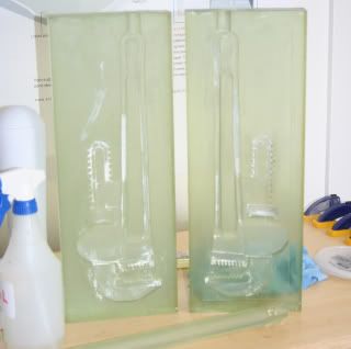
These particular molds we made on a system that goes for about $ 850,000. That dosent includes the 265 Liter of resin at $305.00 a Liter. The real itty bitty stuff we make in a machine that can hold 16 microns and cost a lot less (That a relative statement) but we can only build 8 ½ x 11 ¾ x 7 ½ inch models. the models are out of photo-acrylic great for casting. But don’t worry you will see them soon enough. I’m going to have to hand model the GAU12 I’ll do it in Solidworks and send you some of the renders. Here is a Big mold we did. Its a full size 14" pipe wrench we did several castings in 8lb foam for a movie prop.
I am in the process of buying 1 for my garage its used has an 8x8x8 platform size. I got a good deal on it. But the lase is almost dead (about 200 hours left on it) BUT it will only build .004 layers but I can deal with that. Take a look at http://www.solid-scape.com/index.html
One went last on ebay for 7500.00 I think that you could have a lot of fun with that.
Cheers.
Hey on a side note we got a sample of some new silicone We cant seem to de-gas it its pretty thick and platinum cure. Its made by Smooth-on Smooth-Sil 920. Any Ideas ?
e-
DK666 and RLW -
This is really great stuff - thanks for taking the time to share this info.
I just did my first simple resin casting today, and I’m totally hooked - it worked out great, and it’s nice to see here what complicated things can be done with some clever thought about the molds.
Bruce
I had a sample (same company, plat, may not have been the 920) of it year, 18 months ago and liked it except for the expense. I used a club vaccum pump and chamber and as I recall it did not gas as much as expected. But I didn’t have any problems.
I also tried another method which was to warm up the master (if possible) and dip it into the mixed RTV. There were a couple of surface bubbles and once popped, and filled in with RTV it was then framed and poured normally. It also created quite a mess so I haven’t used that method very often.
The real question is or will be if there are any bubble problems with the slow or minimal de-gas.
- Are there any particular characteristics involved with the scanning.?
- Does color affect it?
- Could the object to be scanned for example, be something in blue plexiglass?
- Is there any restrictions on the 3 dimensions, for example, could an object be 4" X 4" or round and 1/8" thick like a large medallion
- Can it be reduced once it is scanned in?
- Does reduction create a loss of detail to any perciptable degree?
I know there are more questions, but I’m not fully engaged yet this am
BTW
How much is a 3d scanner on the cheap end or used?
Regards RLW
Well Bruce,
Are we going to see any pictures of your endeavor?
And, what else are you planning that we might assist you with? How about a picture of something that you think is complex, and your thoughts on how you intend to proceed?
What is the mold material your using?
Regards RLW
Sure - pictures in a few days - I’m going to take pictures for a group build status report soon and I’ll post a couple of the mold and castings here.
I’m building an vac kit of a Bv.238 - very basic in detail. It’s a 6-engine flying boat, and I wanted to add some detail to the engines. I used the exhausts from a Me.109 kit (same engine type as the Bv.238) as masters. I also carved (okay, the dremel and sanding sticks did most of the work) out of basswood a prop spinner, and also cast that. I thought about doing the prop blades as well, but decided I would start simple to begin with. I’ll probably just make the blades out of styrene sheet this time. I’ve done this before - after forming them I twist them and drop them in hot water to make the twist permanent - works out pretty well.
I’m just using the stuff in MicroMark’s starter kit:
http://www.ares-server.com/Ares/Ares.asp?MerchantID=RET01229&Action=Catalog&Type=Product&ID=82698
I think I’ll need to find a local source for resin, since shipping is pretty pricey from MicroMark. I have a local TAP Plastics store, so I can check out what they have. Other than that store, I can’t think of any local source.
I don’t think I’ll have anything else to cast for this kit (everything else is a one-off detail), but I have a project I just started that will have a ton of casting possibilities. I’m going to scratchbuild an Antonov An-225 and an Antonov An-124 in 1/72 scale. Between the two planes, there’s 10 engines, 24 main landing gears, 48 main gear wheels, 4 front landing gears, 8 front gear wheels. Whew! One of the things I’m trying to think through is how to form the engine nacelles. I want to at least partially detail the interior of the nacelle, so it’s got to be hollow (I also want to keep weight down since I’m worried about wing droop). I’ve thought about carving the masters from basswood (might be tricky to get the hollowed out nacelle?), skinning them with plastic and detailing them, then casting the nacelles in two parts, front and back - seems like I could do that with a single mold and get hollow nacelles. If I cast left-right halves, seems like it would be harder to get a hollow nacelle. I might want to cast the pylons as well as separate parts.
Some photos of the engines and pylons:
http://www.airliners.net/open.file/0673768/M/
http://www.airliners.net/open.file/0288652/M/
http://www.airliners.net/open.file/0037912/M/
and the landing gear:
http://www.airliners.net/open.file/0002541/M/
http://www.airliners.net/open.file/0002540/M/
Any suggestions/thoughts on casting jet engine nacelles and landing gear would be greatly appreciated. I think the wheels should be pretty straightforward, at least. The landing gear might need reinforcement - I’m worried about the overall weight of the models.
Thanks,
Bruce
Ok Bruce, I’m splitting questions and comments into two responses. This one is reference to the engine nacelles. Here is a generic view that I pulled off the web to illustrate the point.
Which parts do you want to inclued? How many components do you want to group together in a single casting? What specific interior detail do you want to show? Aren’t there already some plastic or vac formed engines of the type you want that could form the basis of the mold desired?
None of the individual components are particularry difficult. For example, it would be a piece of cake to make a mold of the Fan Cowl in one casting showing both interior and exterior. However, much planning would have to go into the Front Cowl and the front of the blades.

The nose assembly is straight forward without the tires on. It looks like if a master was available, I would make a mold with the parting line from top to bottom on the main strut, and on a center line that is parallel with the long axis of the plane.
I would then either pour Low Melt Alloy directly into the mold (if made of the right material) or I would follow my Lost Wax Casting procedures and produce a wax, invest it, burn out, and then pour the Low Melt into the cavity.
Either method would require just a minimum amount of cleanup of the parting line.
The pictures don’t show a lot of detail for all of the undercuts, but I don’t think they represent a serious problem, and if they are significant, I would simply make a multipart mold to overcome the undercut areas.
RLW
For the landing gear - that makes perfect sense to make them out of metal - that’ll solve the strength issue. The front gear looks pretty straightforward. I’ll have to look at some more detailed photos and plans that I have for the main gear to see how it’s laid out - it may require multiple parts.
For the engines, I think I need to think about the parts breakdown - I was thinking of just a few parts, but based on your questions and how I want it to look it probably makes sense to make the engines as multiple parts. What I want to do ideally for interior detail is something along the lines of this work:
He’s working in 1/144 scale - at 1/72 things will be a bit different. I think at 1/72, photoetch for fan blades may actually be visibly too thin for the scale, so I’m thinking of making them out of something else. As far as what details to include, I’m thinking the bypass fan, the initial compressor blades and supports, and the final end-stage turbine blades (pretty much what you can see by looking into either end of the engine). I don’t plan on including any open panels with engine detail. So the parts breakdown is something like 1. inlet cowl + fan cowls, 2. fan spinner, 3. blades (maybe PE, but maybe from some other material), 4. exhaust nozzle, 5. exhaust cone, 6. thrust reversers cowling, and 7. the pylon. With that breakdown, I think all of it could be done with simple molds. I’ll probably start working on this in a month or two - I’ve got the reference materials (plans, photos, etc.) I need, and I just need to finish a couple of other projects first.
I have C-17, C-5, and KC-10 vac kits in 1/72 scale - I’ll have to fish them out of the stash and look at the engine nacelles. I’m betting they won’t be the right shape/size to match the Antonovs’ engines, but you’re right it’s definitely worth a look to see if I can use them as starting points. Otherwise, I think I’ll just have to scratchbuild the parts. And I suspect it may take more than one try at it since I’ll have to work out how to put all the parts together as well.
Thanks for the info/suggestions - very helpful ideas to get me thinking about solutions.
Bruce
Im Back.
The reason I have been absent is we host a Annual Rapid Prototype Modelmaking Workshop for Educators we bring in about 50 educators from around the country and Teach them Rapid Prototyping and Modelmaking for a whole week. That being said. RLW I have your models done however I havent had time to ship them yet but I have tomorrow off (well deserved I think) so I will Priority them to you and you can get creative and stun us all with your product of work. BTW do you also need a JSF ? and I just got access to a jewerly patternmaking machine (uses either blue or green casting wax) that I’m just dying to do a part on. I will post some pictures of the conference soom so you can see what it was like. Also we have 2 new laser scanners. The answer to your scanning questions are;
No limit on scanning its free form.
Yes black is bad but we talc the part so its no problem nothing like glass or mirrors (laser passes right through or bounces off)
Yes but we have to talc it first.
I can scan up to 14feet by 14 feet so if its bigger than that I have to target it and stich it together which is no problem I have software for that.
Bigger or smaller no problem just some software settings.
It can but I can remesh it and restore detail.
Cheers
e-