I have not seen anything on this subject before, so I’m asking you folks: how are radial engines attached to an aircraft? I have looked this up but the only stuff I’ve found has to do with how they work, not how they are attached. Thanks, Dave
Usually, there is a metal “hoop” that the engine bolts to, and a welded truss-like structure that holds the hoop to the firewall via bolts.
This is in contrast to WW I aircraft with rotary engines - they are mounted to a pipe that goes through the firewall and have a bracket with bearings. The propeller is bolted to the front of the engine, and the whole thing spins around (for cooling and lubrication). One variation on this is the Siemens-Halske geared rotary engine, where the prop and engine turn in opposite directions! Crazy stuff in WW I.
To be clear, there are radial engines and there are rotary engines. A radial engine has a central crank case that is fixed to the aircraft frame rigidly, usually it is bolted to a frame made of tubing that in turn is bolted to the firewall of the aircraft. The crank case contains a crankshaft with the number of throws matching the number of banks of cylinders. The crankshaft is connected to the pistons by means of a big multi-armed connecting rod.
So the crankshaft rotates relative to the aircraft and spins the prop, through a set of gears.
A rotary (cylinder, not rotor) engine is sort of the opposite. The crankshaft is rigidly mounted to the firewall and the cylinder bank rotates around it. The propeller in turn is usually mounted rigidly to the front of the engine crank case.
Real G, I know about the hoop, but, what I don’t know is how the engine was attached to the hoop. The best I can figure out is possibly 4 bolts either run through the hoop or somehow attached to mounts that hung on the hoop (welded to it?) and I am pretty certain that, somehow, those mounts attached to the crankcase. The reason it’s important is I’m building a TBF Avenger, I’m thinking of exposing the engine and I know that the mounting mechanism is totally wrong. Trumpter gives me a flat piece of plastic that is cemented to the hoop. I know that’s not right. Dave

When I volunteered at the National Warplane Museum in the early 80s, there were two types of engine changes we would do on the B-17 - a 4 point and an 8 point. A 4 point unbolted the 4 bolts that attached the engine mount to the firewall to remove the entire mount, the 8 point unbolted the 8 bolts attaching the engine to the mount. The 4 point was much easier, but resulted in quite a bit heavier a lift.
Stikpusher (and G Morrison), Thanks for the pics. Looks like i’ll have to thin down the plate quite a bit and manufacture some attaching lugs and attach a tube or solid round stock to the crankcase. Simple!!?? Dave
David, the ring is bolted to the crankcase, but between the two are what is called Lord mounts, for vibration isolation.
Here’s a picture of an R-2800 with the engine mount ring removed. The Lord mounts are the gray devices with studs sticking out, these bolt through the mount ring. These are the Dynafocal type Lord mounts which came into use during WW II and the engine is from a Lockheed PV-2 Harpoon. Lord was the name of the company that made them. Dynafocal mounts isolate vibration about all three axes of rotation.

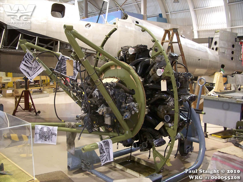
This is the photo Carlos posted above, but I have marked the Lord mounts, which are of the earlier type. There are ears on the front of the mount ring that these fit between and are bolted to. This is a Wright R-2600 from a TBM. This type of mount mostly isolates vibration about the longitudinal axis.


They use what is called Lord mounts, because they where made by Lord manufacturing. It is a two piece steel engine mount with rubber in between the two. The engine side bolts to the engine crank case onto 4 studs and the engine mount side bolts to the “hoop” with one larger bolt. It is the same principal as any car engine mount, the rubber isolates the harmonic vibrations from the rest of the vehicle. Lord manufacturing is still around. They make isolation mounts for industrial machinery and their website will give you a good idea of the design. The engine mounts are usually so far down on the crank case that you would never see them is a modeling situation. They are covered by exhaust and intake manifolds and the accessories as well as various other ducting, wiring and such. Tim
There are bolts or studs that protrude from the rear of the crankcase. There are bosses at the base of the studs (or threaded hole) and the bosses are machined to a plane. These match up with holes and surfaces on the hoop. By the way, that hoop is not always a circle. It may be other shapes (squares, pentagon or hexagon), but it encircles the crankcase of the engine. Then there are struts protruding from the fireway to that hoop. Often electrical wires, plumbing lines, bodine (control) cables and such attached to these struts with tie wraps or metal retaining strips and hold the cables from flopping around.
There are a number good photos of this stuff online. Go to Google, select image search, and type in a plane or engine and say engine mounting or firewall.
Thanks, Don, and all who answered. The “problem” is, that Trumpeter decided that there was a piece of “armor plate” (at least that is what the thickness suggests) that is directly attached to the mounting ring, and the engine is “bolted” (cemented) to this armor plate. I know that this isn’t right so I’ll probably end up makig some (maybe 6) Lord mounts to attach the ring. Dave
Did Trumpeter provide the rear part of the engine behind the mounting ring/ plate?
At some point it might make sense to use a more highly detailed engine.
Some of the Trumpeter engines also have too much distance between the banks of cylinders. The engine in the old Hasegawa F6F is a better exmple of an R-2800.
I forgot to mention the vibration absorbers. A number of firms made mounts that were basically a mounting bolt, stud, threaded hole, or whatever glued or captured on both sides of a block of rubber. I am not sure when they began to be used. I think it must have been between the wars. Most WW1 engine mountings I have seen were hard fastened, but most by WW2 did have vibration absorbing mounts.